Zum Inhalt springen

Warenkorb

Dein Warenkorb ist leer

Weiter einkaufen

0.5" Micro OLEDoS Display 1600x1200 120Hz 1000nits - MIPI

SKU: DM-OLED050-1005
Angebot$299.00
  • 💹 Enjoy a 20% discount for orders over 500
  • 📉 A 15% discount is available for orders ranging from 200 to 499
  • 🎁 A 10% discount is available for orders ranging from 50 to 199
  • 🎁 A 5% discount is available when ordering 10-49

Interested in customizing this product? Get in touch with us.

Order samples, immediate delivery.

Factory bulk lead time: 3 weeks.

Set: Screen Only

Teilen
0.5" Micro OLEDoS Display 1600x1200 120Hz 1000nits - MIPI DisplayModule
0.5" Micro OLEDoS Display 1600x1200 120Hz 1000nits - MIPIScreen Only Angebot$299.00

Resources & Downloads

DM-OLED050-1005 · Micro OLEDoS Display Module

0.5-Inch Micro OLEDoS Display, 1600×1200, 120Hz, 1000 cd/m², MIPI Interface

This 0.5-inch Micro OLEDoS display module uses a single-crystal silicon backplane with integrated panel-driver and logic-driver circuits. It is designed for compact near-eye display evaluation, electronic viewfinder systems, and head-mounted display projects requiring high resolution, high contrast, compact dimensions, and MIPI-based video input.

The module provides 1600(H) × 1200(V) real RGB resolution, 1000 cd/m² luminance, a 100,000:1 typical contrast ratio, 90% DCI-P3 color-gamut coverage, 60Hz to 120Hz frame-rate operation, MIPI and I2C interfaces, VESA DSC v1.1 decoding, a 6.3μm pixel size, and a 10.08mm × 7.56mm usable display area.

1600 × 1200

Real RGB Resolution

1000 cd/m²

Luminance

100,000:1

Typical Contrast

MIPI + I2C

Video + Control

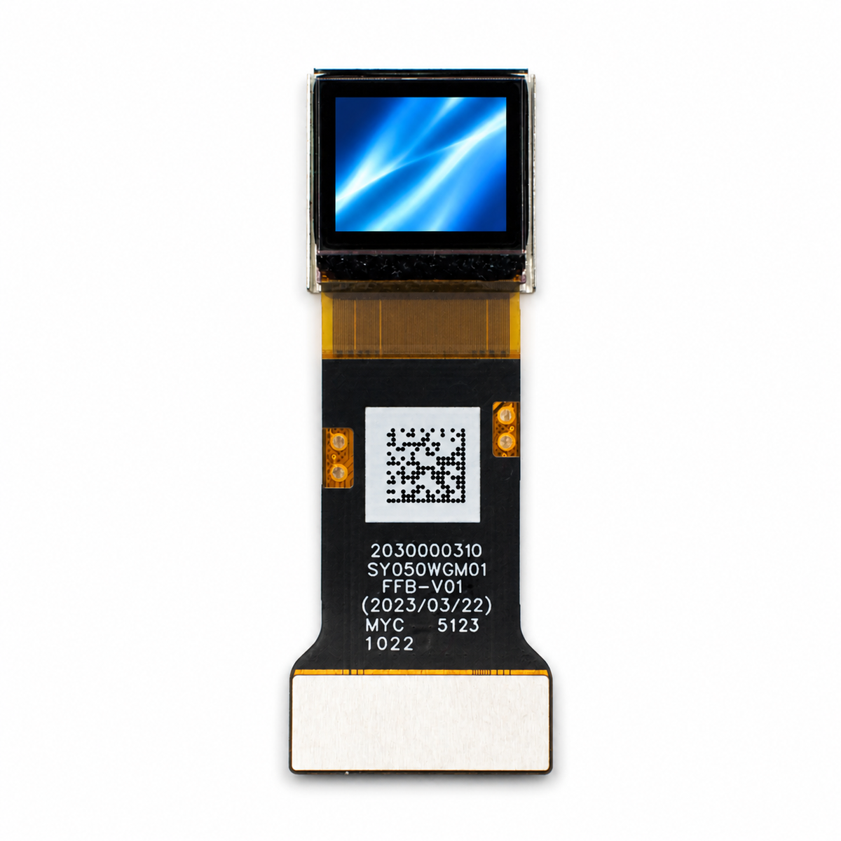
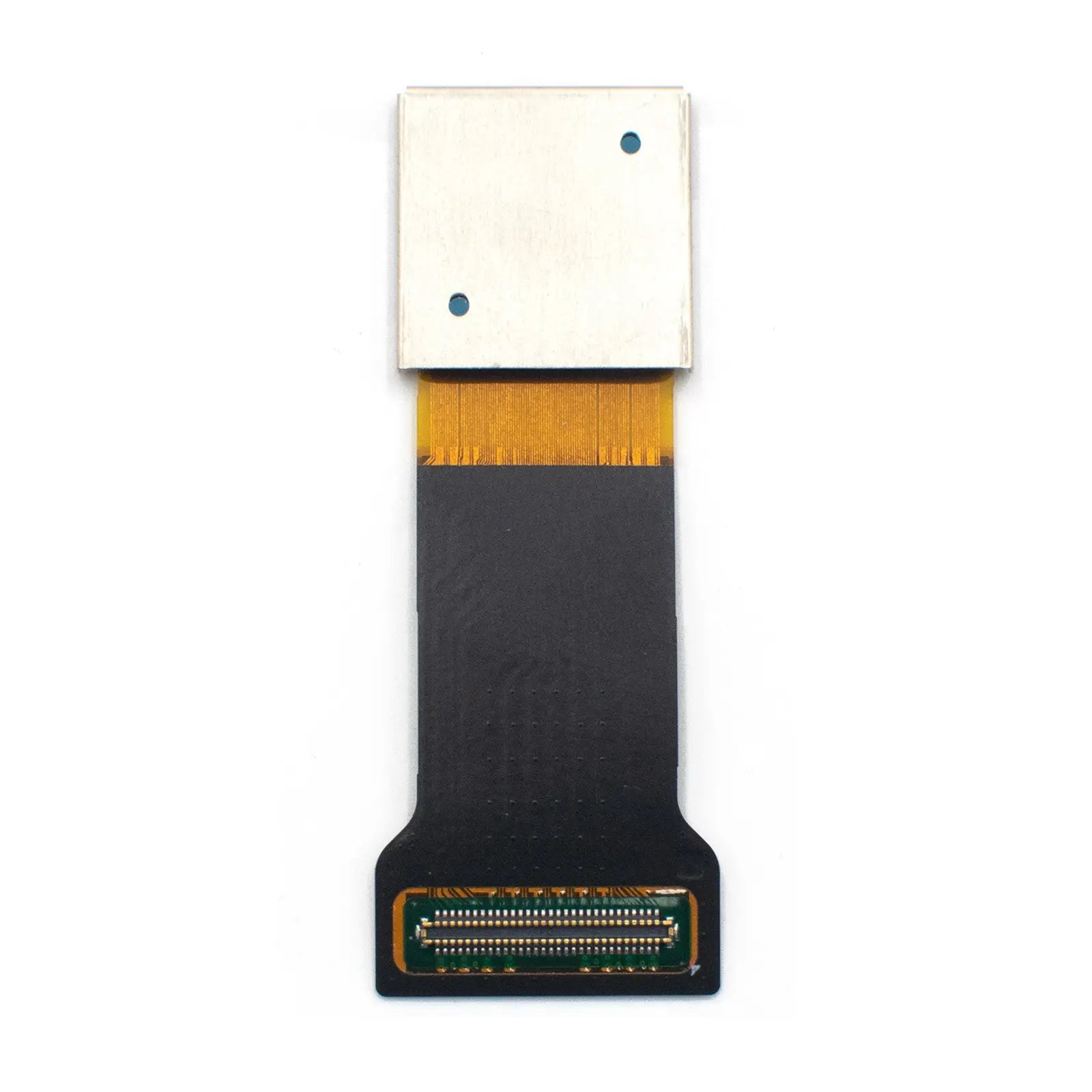
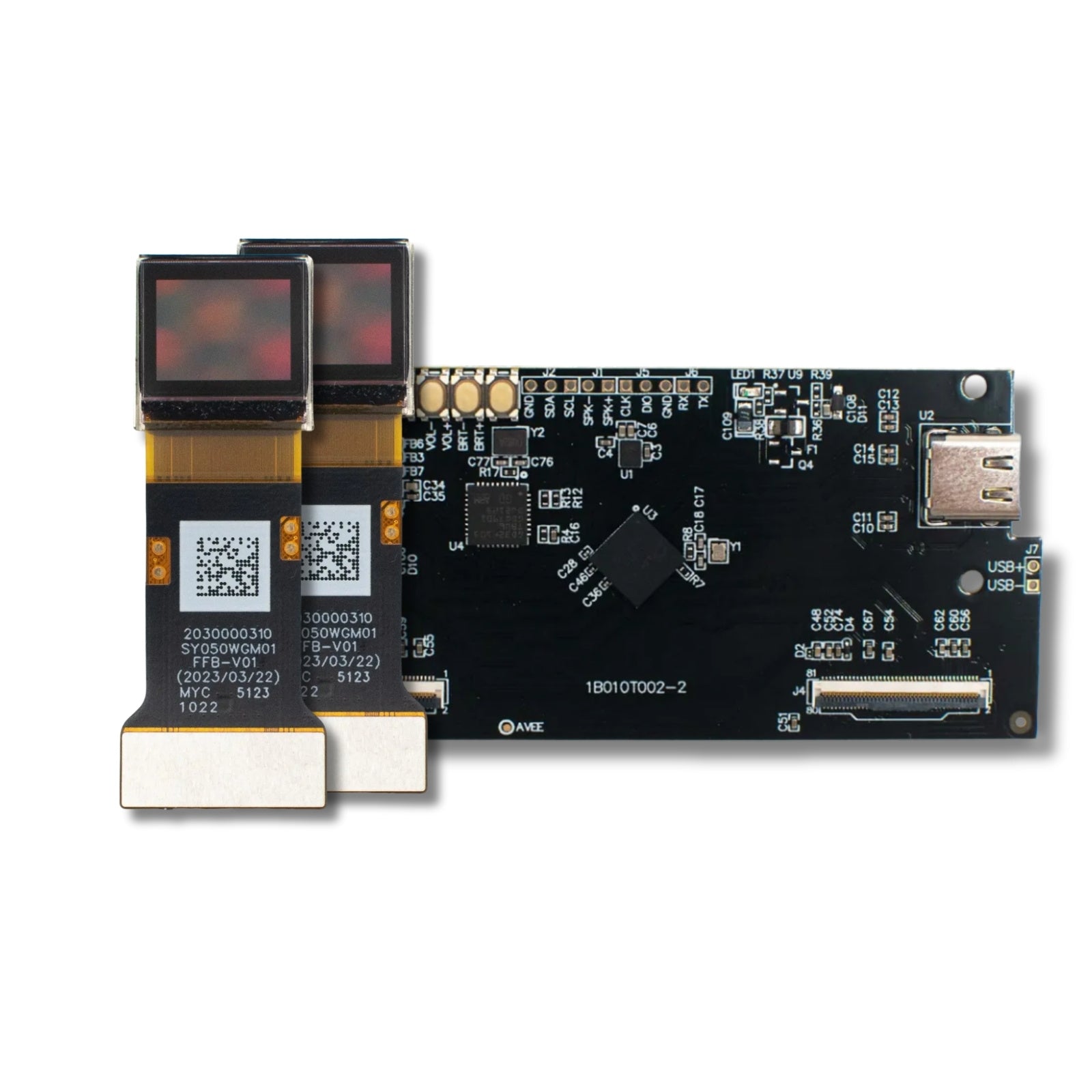
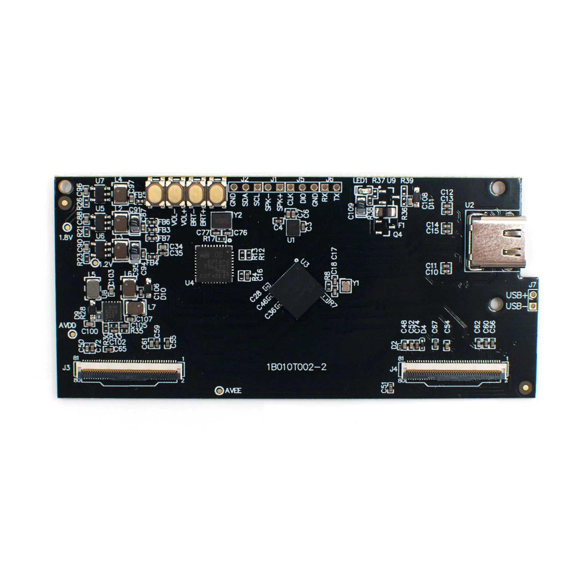
DM-OLED050-1005 0.5-inch Micro OLEDoS display module front and back view

Display Area: 10.08mm × 7.56mm

Pixel Size: 6.3μm

Frame Rate: 60–120Hz

Optical Performance Data

Calculated at Approximately 4000 PPI

Pixel density is calculated from 1600 pixels across a 10.08mm active width and 1200 pixels across a 7.56mm active height. This density helps reduce visible pixel structure in magnified near-eye optical systems.

1000 cd/m² Luminance

The luminance value is specified at the display-module level. Final eye-side brightness depends on optical efficiency, lens or prism transmission, coating design, mechanical light leakage, and operating conditions.

100,000:1 Typical Contrast

OLED self-emissive pixels support deep-black image areas without LCD backlight leakage. Perceived contrast should still be verified inside the completed optical engine and enclosure.

90% DCI-P3 Color Gamut

The specified color coverage supports vivid display output. For color-sensitive systems, gamma, white point, calibration, brightness level, and the completed optical stack should be tested together.

Product Specifications

Parameter Specification Engineering Note
Display Type Micro-OLED / OLEDoS Active-matrix color OLED panel module built on a single-crystal silicon transistor backplane.
Display Size 0.5-inch diagonal Compact format for near-eye display modules, electronic viewfinders, and head-mounted display evaluation.
Resolution 1600(H) × 1200(V) Real RGB resolution for detailed symbols, user interfaces, viewfinder previews, and optical-engine testing.
Number of Dots 5.76M (1600 × 1200 × 3) RGB dot count based on the module specification.
Usable Display Area 10.08mm × 7.56mm Used when calculating optical magnification, field of view, and mechanical alignment requirements.
Pixel Size 6.3μm × 6.3μm The small pixel pitch supports high pixel density in magnified optical systems.
Pixel Density Calculated at approximately 4000 PPI Calculated from the active display area and resolution; confirm suitability through complete optical-system evaluation.
Luminance 1000 cd/m² Display-side luminance; final eye-side brightness depends on optical transmission efficiency and operating conditions.
Contrast Ratio 100,000:1 typical OLED self-emission supports deep-black image areas without a separate backlight unit.
Uniformity >85% Uniformity evaluation should follow the measurement conditions defined in the datasheet.
Color Gamut 90% DCI-P3 Final color accuracy depends on calibration, gamma settings, brightness, and optical-stack design.
Gray Levels 256 / 1024, mode dependent Available gray-level depth depends on the selected driving and image-data configuration.
Frame Rate 60Hz to 120Hz Host-controller timing, thermal behavior, signal bandwidth, and power margin should be verified at 120Hz.
Interface MIPI + I2C MIPI carries display data, while I2C is used for commands and register configuration.
MIPI Physical Layer MIPI D-PHY v1.1, 1 port, 4 lanes, 1.0Gbps/lane Check the host platform for lane count, lane speed, timing compatibility, and initialization requirements.
MIPI DSI Mode MIPI DSI v1.02 r11 video mode Use the specified initialization sequence and timing requirements during controller bring-up.
Compression VESA DSC v1.1 decoder, 3:1 and 3.75:1 ratios Compression mode, bandwidth margin, output timing, and image quality should be tested on the target SoC.
Scaling ×1.33 and ×2 supported Supports 1200×900 to 1600×1200 and 800×600 to 1600×1200 scaling modes.
Power Consumption 500mW typical Actual consumption varies with image content, brightness, frame rate, initialization settings, and operating temperature.
Operating Temperature −20°C to +70°C System-level operation should be tested inside the completed enclosure and thermal design.
Storage Temperature −40°C to +80°C Relevant to warehousing, transport, logistics, and non-operating product storage.
Weight TBD The preliminary datasheet lists the weight as TBD. Do not use a fixed value until it has been confirmed.

Interface, Compression & Driving Architecture

MIPI DSI Video Input

The module uses MIPI DSI video mode with MIPI D-PHY v1.1. The one-port, four-lane configuration at up to 1.0Gbps per lane should be matched to the host controller, connector, PCB routing, and initialization design.

VESA DSC v1.1 Decoder

The integrated DSC decoder supports 3:1 and 3.75:1 compression ratios. Compression settings, output timing, bandwidth, visual quality, and host compatibility should be validated on the selected controller platform.

I2C Register Control

I2C is used for commands and register configuration. Brightness adjustment, scan direction, scaling mode, temperature compensation, and initialization should follow the official datasheet and approved register sequence.

Electrical & Optical Design Checklist

Power & Thermal Margin

The 500mW figure is a typical specification. Validate temperature rise, enclosure heat dissipation, brightness, frame rate, image content, supply stability, and full-white operation in the completed device.

MIPI Signal Integrity

Route MIPI differential pairs with controlled impedance, closely matched lengths, minimal stubs, a continuous ground reference, and reliable connector contact. Keep high-speed lanes away from noisy switching-power areas.

Optical Alignment

Check the active-area position, optical center, panel tilt, FPC exit direction, lens distance, display orientation, alignment method, and mechanical tolerances before tooling.

Reliability Review

Review initialization stability, brightness uniformity, image-retention risk, temperature exposure, humidity, vibration, storage conditions, supply sequencing, and long-duration operating behavior.

Application Fit by System Type

Head-Mounted Displays

The 0.5-inch display area, high calculated pixel density, compact format, and 60Hz to 120Hz operating range support near-eye display and head-mounted optical-system evaluation.

Electronic Viewfinders

The 1600×1200 resolution, 100,000:1 typical contrast ratio, and 90% DCI-P3 specification support EVF prototypes and compact optical-viewer development.

Medical Imaging Display Evaluation

The module may be evaluated for medical imaging display systems that require compact, high-resolution visualization. Final use depends on complete-device design, optical validation, reliability testing, risk management, and applicable regulatory requirements.

Industrial Optical Equipment

The module can be evaluated for handheld inspection tools, compact measurement instruments, microscope viewing systems, and other optical products requiring a small high-resolution display.

Technical FAQ

What is the pixel density of this 0.5-inch Micro OLEDoS display?

The calculated pixel density is approximately 4000 PPI, based on 1600 pixels across a 10.08mm active width and 1200 pixels across a 7.56mm active height.

Does this display support 120Hz operation?

Yes. The specified frame-rate range is 60Hz to 120Hz. For 120Hz operation, validate MIPI timing, DSC settings, power stability, image quality, and thermal behavior on the target controller.

Which interface does this module use?

The module uses MIPI for display data and I2C for commands and register control. The physical layer is specified as MIPI D-PHY v1.1 with one port, four lanes, and up to 1.0Gbps per lane.

Can this module be used directly in medical equipment?

The module can be evaluated for medical imaging display systems, but final use depends on the complete device, optical design, electrical safety, regulatory requirements, reliability testing, and system-level validation.

Downloads, Product Page & Engineering Support

Use the datasheet to review electrical characteristics, interface requirements, optical specifications, operating conditions, and integration details. For controller compatibility, initialization guidance, or project-specific questions, contact the DisplayModule engineering team before production release.

From $299

Screen-Only Price

5%–20%

Volume Discount Tiers

Approximately 3 Weeks

Factory Bulk Lead Time

Reviews from our customers