









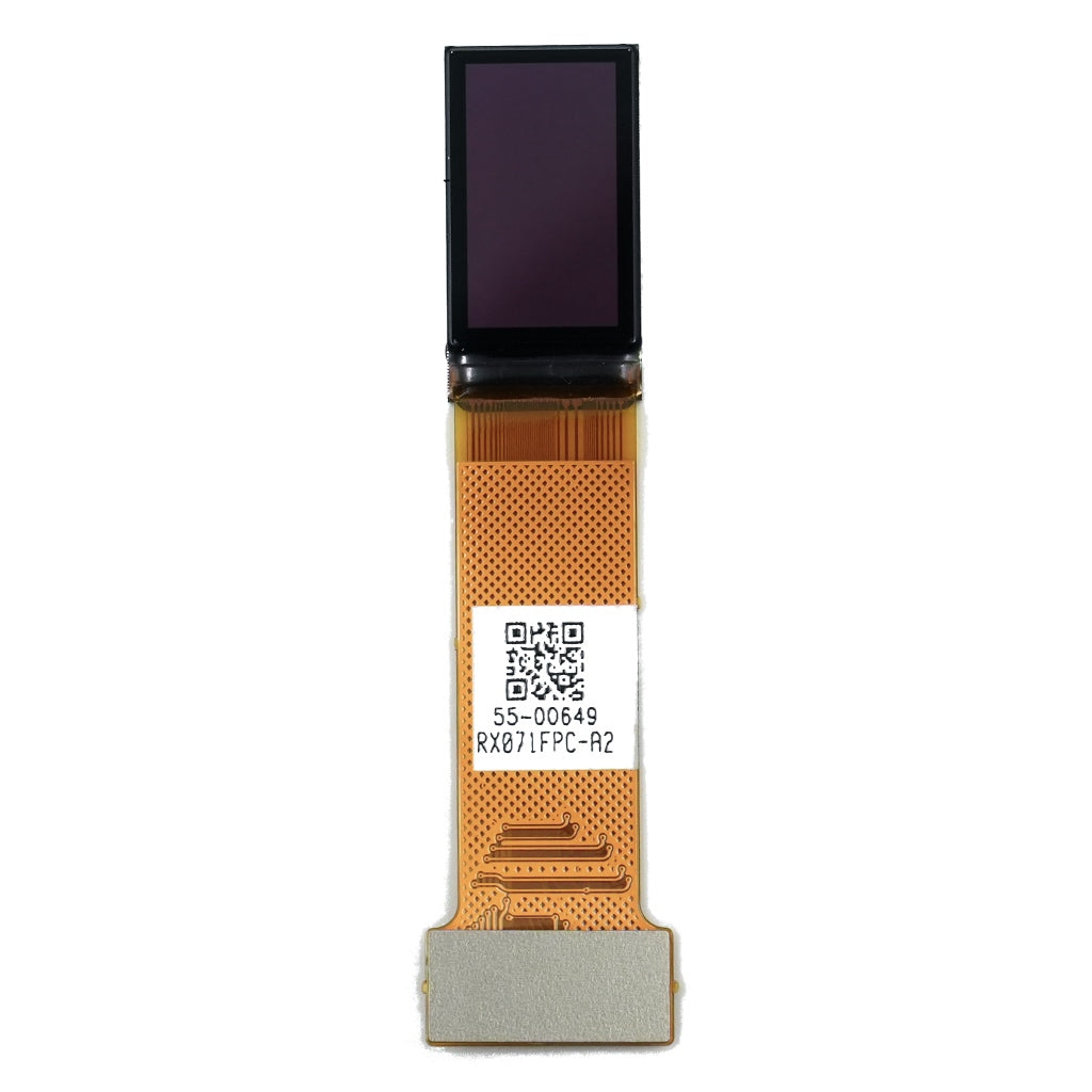
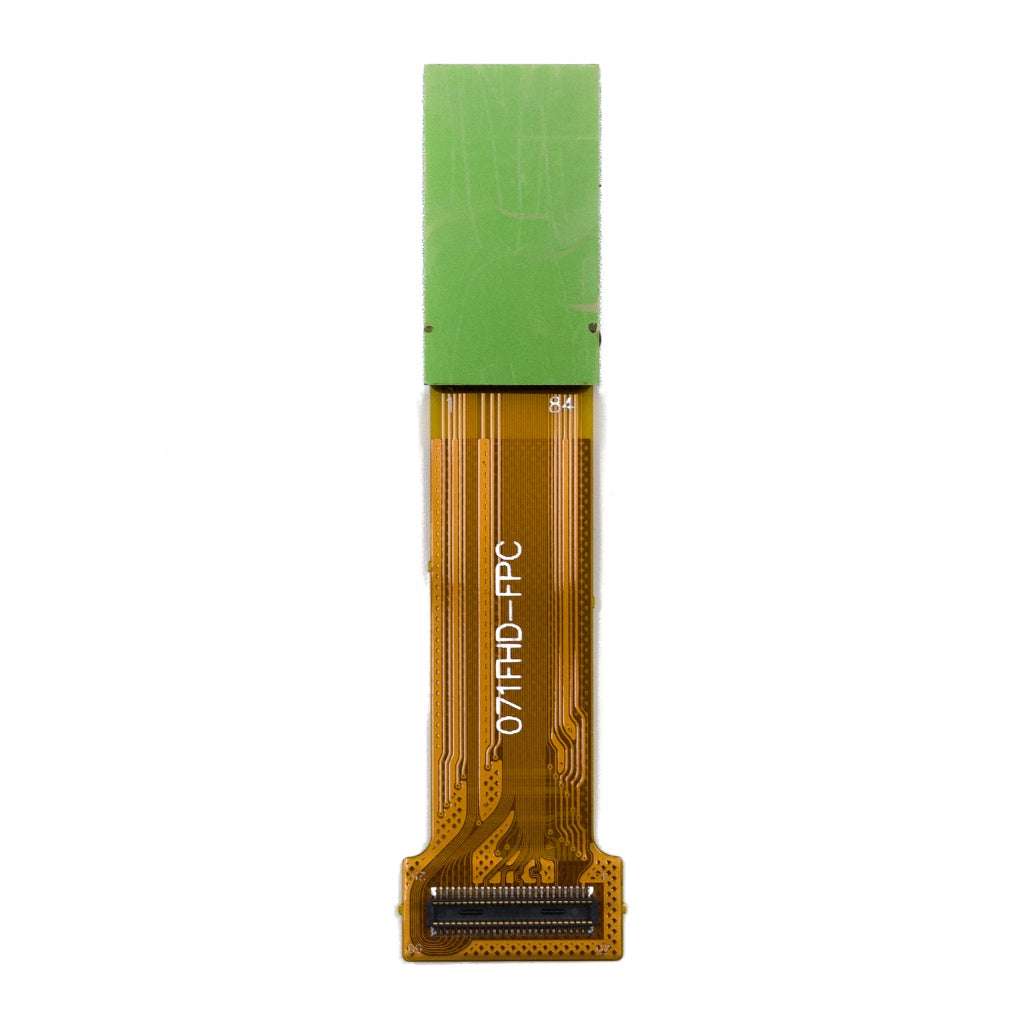
0.71" AMOLED Display 1080×1920 FHD+ – MIPI DSI Interface
- 💹 Enjoy a 20% discount for orders over 500
- 📉 A 15% discount is available for orders ranging from 200 to 499
- 🎁 A 10% discount is available for orders ranging from 50 to 199
- 🎁 A 5% discount is available when ordering 10-49
Interested in customizing this product? Get in touch with us.
Order samples, immediate delivery.
Factory bulk lead time: 3 weeks.
0.71" AMOLED Display 1080×1920 FHD+ – MIPI DSI Interface
- 💹 Enjoy a 20% discount for orders over 500
- 📉 A 15% discount is available for orders ranging from 200 to 499
- 🎁 A 10% discount is available for orders ranging from 50 to 199
- 🎁 A 5% discount is available when ordering 10-49
Resources & Downloads
0.71" AMOLED Microdisplay 1920 × 1080 FHD with 4-Lane MIPI DSI
DMRXO0071FHNB is a 0.71-inch silicon-based AMOLED microdisplay built with top-emission, high-efficiency active OLED technology. It provides 1920 × 1080 Full HD resolution at datasheet-listed 3135 PPI pixel density and is designed for near-eye display systems requiring miniaturized, high-resolution, and low-power display solutions.
The module uses a FHD02 driver IC, supports MIPI DSI (D-PHY v1.2, 4-lane) plus I2C interfaces, and integrates temperature compensation, brightness adjustment, image mirror, and built-in test patterns within a 60.40 × 15.10 × 1.49 mm structure.
Technical Specifications
Key technical information sourced from the official datasheet (V1.0.0, Oct 28, 2025). These values support display selection, mechanical layout, interface review, and sample evaluation.
| Parameter | Specification |
|---|---|
| Product Model | DMRXO0071FHNB |
| Display Technology | Silicon-based AMOLED, top-emission, high-efficiency active OLED |
| Screen Size | 0.71 inch diagonal |
| Active Area | 15.8139(H) × 9.0087(V) mm |
| Module Outline | 60.40(H) × 15.10(V) × 1.49(D) mm |
| Resolution | 1920(H) × 1080(V) Full HD |
| Sub-Pixel Size | 4.6 µm × 4.68 µm |
| Pixel Array | RGB Irregular Hexagon |
| Pixel Density | 3135 PPI (datasheet-listed) |
| Display Colors | 16.7M colors (8-bit / 256 gray levels) |
| Driver IC | FHD02 Micro AMOLED Display Controller / Driver |
| LCM Interface | MIPI DSI (4-lane) + I2C |
| MIPI DSI | D-PHY v1.2, DSI v1.01 R11, 1 port / 4 channels, HS speed 500 Mbps to 1.0 Gbps per lane, Video Mode (Burst Mode) |
| I2C Interface | 100 kHz to 400 kHz, slave address 0x4C (when IM[0] = 1) |
| Connector | HCTL HC-PBB40C-50DS-0.4V-1.5-02, 50-pin |
| Net Weight | < 2 g |
| Operating Temperature | -40°C to +65°C |
| Storage Temperature | -55°C to +85°C / +90°C subject to final engineering confirmation |
| Operating Humidity | ≤ 85% RH (without condensation) |
Optical Characteristics
Optical data is measured at 23°C ± 2°C, V5.0 = 5.0 V, V1.8 = 1.8 V, PCLK = 148.5 MHz. All pixels are fully on at the highest gray level unless otherwise noted.
500 cd/m² Typ.
Typical brightness is 500 cd/m² with a maximum of 2000 cd/m². Default brightness is approximately 300 cd/m². Recommended adjustable range: 140 to 500 cd/m² via registers 5100h and 5101h.
> 10000:1
Contrast ratio is specified as greater than 10000:1, measured between highest gray and minimum gray levels.
73% NTSC Typ.
Typical color gamut coverage is 73% NTSC (range 66% to 86%). White point CIE coordinates: x = 0.31 ± 0.05, y = 0.33 ± 0.05.
> 90% (Typ. 95%)
Luminance uniformity is greater than 90% with a typical value of 95%, measured using a 9-point method.
25 Hz to 90 Hz
The module supports a refresh rate range of 25 Hz to 90 Hz. At 1920 × 1080 resolution, the frame rate can reach up to 90 Hz, subject to host timing and compression configuration.
20,000 Hours
The rated operating life is 20,000 hours for the full color version under specified operating conditions.
Power Rails and Signal Details
The following values support early power-architecture planning, PCB design review, and processor-interface evaluation. All values are from the datasheet rated operating range.
AVDD 5.0 to 5.5 V
Typical value is 5.0 V. VIN rated range is 4.8 to 5.5 V. Maximum supply current is 500 mA. Verify PMIC output stability before PCB layout.
AVEE -5.5 to -5.0 V
Typical value is -5.0 V. Power stability should be checked together with the power-on sequence specified in the datasheet.
VDDI 1.7 to 1.95 V
Typical value is 1.8 V with typical current of 50 mA (max 100 mA). Check processor I/O compatibility before PCB layout.
MIPI Video Timing (1920 × 1080 @ 60 Hz)
The supported video timing for 1920 × 1080 at 60 Hz is listed below. Refer to the datasheet for complete timing parameters, register configurations, and low-power mode timing.
| Timing Parameter | Value |
|---|---|
| Pixel Clock (PCLK) | 148.5 MHz |
| H TOTAL / V TOTAL | 2200 / 1125 |
| HSYNC / VSYNC | 44 / 5 |
| HACTIVE / VACTIVE | 1920 / 1080 |
| H Back Porch (HBPR) / V Back Porch (VBPR) | 148 / 36 |
| H Front Porch (HFPR) / V Front Porch (VFPR) | 88 / 4 |
| MIPI Lanes | 4 Lanes @ 60 Hz |
| Clock Mode | Discontinue Mode |
| Video Mode | Burst Mode |
| General Packet Structure | DCS Mode, Data Type 0x39 or 0x05 or 0x15 |
| VESA-DSC | Internal decoder supports 3x and 3.75x compression ratios |
Functional Features
The FHD02 driver IC integrates several functional modules to support near-eye display applications. These features are configured via MIPI or I2C registers.
Built-in Temperature Sensor
A built-in temperature sensor provides real-time temperature reading via the ADC module. Supports temperature compensation and abnormal power-off protection when temperature exceeds a configured threshold. Hysteresis level and threshold are register-configurable.
140 to 500 cd/m² Adjustable
Brightness is adjusted via registers 5100h (DBV[7:0]) and 5101h (DBV[8]). Default value is 0x0000 (darkest). Maximum value is 0x01FF (brightest). Brightness enable is controlled by register 53h.
1.33x and 1.5x Zoom
Supports 1.33x scaling (from 1440 × 810 to 1920 × 1080) and 1.5x scaling. Compatible with lower-resolution input formats such as 1440 × 1080 and 1280 × 1024 via register configuration.
Horizontal and Vertical Flip
Supports horizontal and vertical image mirror via the MADCTL register (36h). Also supports RGB/BGR color order selection for flexible optical system integration.
Upward or Downward
Scan direction selection (upward or downward) is supported, allowing flexible mounting orientation in near-eye optical systems.
BIST Function
BIST function with multiple test patterns including red, green, blue, black, gray level, vertical and horizontal gradation, color bar, fringe, and gamma patterns for production testing and evaluation.
Engineering Notes for Product Integration
Power On/Off Sequence
Strictly follow the datasheet sequence: VDDI → AVDD → AVEE → hardware reset → OTP loading. Power-off reverses this order. Incorrect sequencing may damage the AMOLED panel.
MIPI Timing Configuration
Verify DSI clock, lane mapping, and timing parameters against your host processor before PCB routing. Refer to the MIPI Video Timing section below for 1920 × 1080 @ 60 Hz parameters.
Connector Matching
Confirm the mating connector for the HCTL HC-PBB40C-50DS-0.4V-1.5-02 (50-pin) connector against the datasheet mechanical drawing before PCB layout. Verify FPC routing and pin assignment.
Optical System Integration
This is a microdisplay designed for near-eye display systems. An appropriate optical system is required to achieve the intended large-screen viewing effect. Confirm optical design requirements with your optics team.
Touch Configuration
Touch functionality is not specified in the current datasheet and is normally not integrated for this near-eye microdisplay module.
Sample Availability and Customization
Customization options, if required, should be confirmed with DisplayModule before project design-in. Contact DisplayModule for current sample availability, pricing, production lead time, and customization scope.
Reliability Conditions for Project Evaluation
The operating and storage temperature ranges below help engineering teams review environmental tolerance before sample evaluation and product design.
Operating Temperature
-40°C to +65°C. These conditions help customers review environmental tolerance for normal operation in near-eye display systems.
Storage Temperature
-55°C to +85°C / +90°C subject to final engineering confirmation. Storage temperature range supports logistics, warehousing, and pre-assembly handling review.
Operating Humidity
≤ 85% RH without condensation. Humidity conditions should be reviewed together with product enclosure and sealing design.
Common Questions Before Sample Evaluation
What is the actual display size and pixel density?
The display is 0.71 inches diagonal with an active area of 15.8139 mm × 9.0087 mm and a datasheet-listed pixel density of 3135 PPI.
What interfaces does the module support?
MIPI DSI (4-lane) and I2C. Interface mode is selected by the IM[0] pin: MIPI only or I2C + MIPI. See the Technical Specifications table for detailed protocol parameters.
What is the typical power consumption?
Full color at 500 cd/m² (60 Hz, all-white): 285 mW. Display OFF: 71.4 mW. Power Down: 23.5 mW. See the Power Rails section for details.
What is the operating temperature range?
Operating: -40°C to +65°C. Storage: -55°C to +85°C / +90°C subject to final engineering confirmation. Humidity: ≤ 85% RH. See the Reliability section for details.
Does this module support touch input?
Touch input is not specified in the current datasheet and is normally not integrated for this near-eye microdisplay module.
Can the module display lower-resolution content?
Yes. The module supports 1.33x and 1.5x scaling and is compatible with lower-resolution formats such as 1440 × 1080 and 1280 × 1024 via register configuration.
What driver IC does the module use?
The FHD02 Micro AMOLED Display Controller / Driver, integrating MIPI DSI, I2C, Gamma correction, temperature sensor, OTP, and BIST test modules.
What should be reviewed before PCB layout?
50-pin connector match, MIPI lane mapping, power-on sequence, reset timing, power rails, and IM[0] pin setting. See Engineering Notes for details.
Download the DMRXO0071FHNB Datasheet
Download the official datasheet for full electrical specifications, DC characteristics, DSI timing, optical data, register descriptions, power-on/off sequence, and mechanical drawings to support your integration review.
Confirm dimensions, interface details, connector matching, and mechanical requirements before placing an order.