IM1 = 0
IM0 = 0 selects 8-bit parallel operation. IM0 = 1 selects the 16-bit parallel bus.


Popular Products
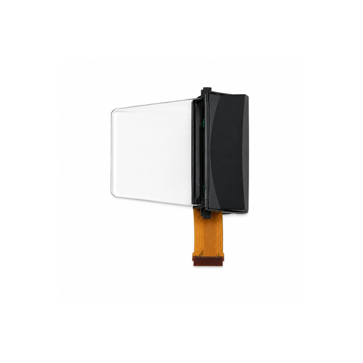
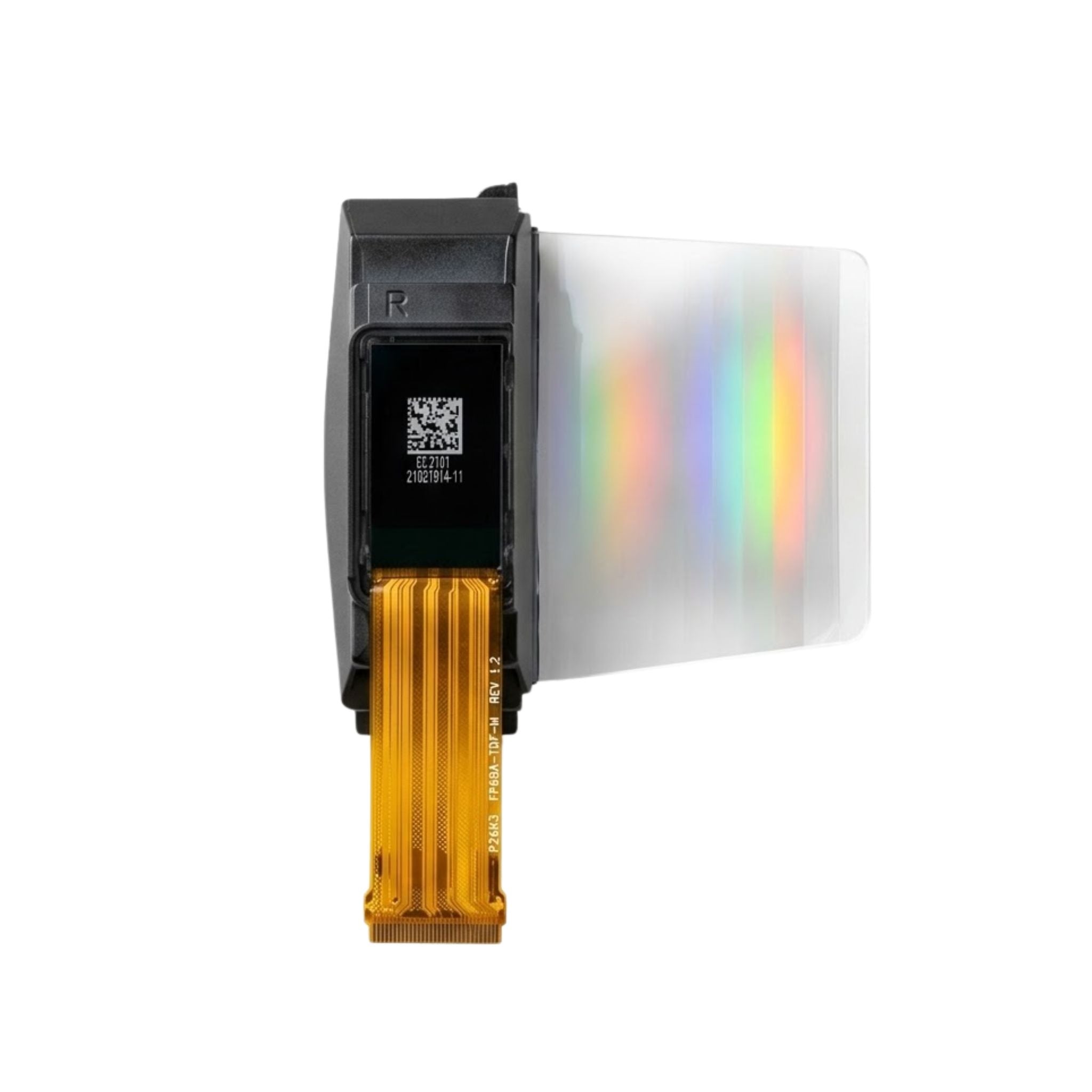


DM-TFT18-309
Choose the image connection to suit your host architecture. DM-TFT18-309 is a 1.77-inch non-touch TFT with MCU, serial and RGB options, a 128 × 160 matrix and a 5.9 g assembly.
Its ILI9163 controller and hardware mode pins define the selected connection. The three-LED backlight is rated at 300 cd/m² minimum and 360 cd/m² typical luminance.
 + Click to enlarge
The ILI9163 display supports parallel MCU, 3-wire or 4-wire serial, and 16-bit or 18-bit RGB connections. Parallel widths of 8, 9, 16 and 18 bits are selected through IM0 and IM1.
IM2 selects parallel or serial operation, RCM1 selects RGB or MCU operation, and SPI4W selects the serial format. The selected mode defines the data and control roles of the shared pins.
IM1 and IM0 select the width of the MCU data bus. This hardware selection is part of the full interface configuration, alongside IM2, RCM1 and SPI4W.
IM0 = 0 selects 8-bit parallel operation. IM0 = 1 selects the 16-bit parallel bus.
IM0 = 0 selects 9-bit parallel operation. IM0 = 1 selects the 18-bit parallel bus.
IM2 = 1 selects parallel and IM2 = 0 serial. RCM1 selects MCU at 0 and RGB at 1; SPI4W selects 3-wire serial at 1 and 4-wire serial at 0.
The complete mode-pin combination defines the connection. The parallel-width selection on its own is not a complete serial or RGB configuration.
Interface-selection reference →The physical connection and initialization sequence work together to produce the image.
Use command and pixel transfers for MCU or serial operation. For RGB operation, the host also provides the pixel clock, synchronization and data-enable signals.
Set the host pin assignment and transfer method to match IM0, IM1, IM2, RCM1 and SPI4W for the intended interface.
The shared pins change roles with the interface. Use the connection reference alongside the mode settings, including the specified treatment of unused pins.
The 45-pin connector reuses data positions across MCU, serial and RGB modes. Its unused-pin instructions are specific to the selected connection.
D0 provides the serial input/output signal in serial mode. D17–D1 are unused in that mode and are specified to connect to ground.
PCLK, DE, HSYNC and VSYNC provide RGB timing. When unused, these timing pins are specified at ground level.
The read-enable pin is connected to VDD when readback is unused. RESET is active low, and CS enables the selected display at a low level.
Keeping mode selection and unused-pin treatment together avoids treating the same connector position as a fixed function in every mode. The pin reference provides the complete connection for this SKU.
Mode-dependent pin reference →| Parameter | Specification |
|---|---|
| Product model | DM-TFT18-309 |
| Display size | 1.77 inch |
| Resolution | 128 × 160 pixels |
| Display connection | MCU / 3- or 4-wire SPI / 16- or 18-bit RGB |
| Controller / panel | ILI9163 |
| Display colours | 65K |
| Touch configuration | No touch |
| Supply | 2.5–4.2 V; 3.3 V typical |
| Luminance | 300 cd/m² minimum; 360 cd/m² typical |
| Operating / storage temperature | −20 to +70 °C / −30 to +80 °C (absolute maximum ratings) |
The panel logic uses 3.3 V typical within a 2.5–4.2 V range, with 1.5 mA typical operating current at 3.3 V. LEDK and LEDA1–LEDA3 connect the three-LED backlight.
The backlight has a 3.2 V typical forward voltage and 60 mA typical forward current. Luminance is 300 cd/m² minimum and 360 cd/m² typical; contrast is 400:1 minimum and 500:1 typical.
DM-TFT18-309 provides a 1.77-inch, 128 × 160 image in 65K colours and weighs 5.9 g. Pins 41–44 are no connection on this non-touch model.
The preferred viewing direction is 12 o’clock, with typical angles of 45° top/left/right and 20° bottom. The mechanical drawing provides the panel outline and 45-pin flexible connection for the host assembly.
The panel has an 8 ms typical optical response at 25 °C, with a 16 ms maximum. Its directional viewing-angle limits complement the 360 cd/m² typical luminance specification.
The optical uniformity figure describes the illumination across the panel. It is a different measure from contrast or centre luminance.
Typical viewing angles in these three directions are 45°. The bottom direction is specified at 10° minimum and 20° typical.
Typical contrast is 500:1. These are optical ratios; the display interface and host software determine how image data is transferred.
The screen’s preferred viewing direction is 12 o’clock. For fixed installations, the user’s line of sight and the module’s physical orientation should be considered together.
Optical-characteristics reference →For the MCU/serial image path, RCM1 = 0 selects MCU operation, IM2 = 0 selects serial, and SPI4W = 0 selects 4-wire serial. Use the matching serial pin assignment and initialization; IM0/IM1 alone do not select this mode.
In MCU serial mode, D0 serves as serial input/output. D17–D1 connect to ground, and unused PCLK, DE, HSYNC and VSYNC are also held at ground according to the module pin table.
No. Pins 41–44 are NC on DM-TFT18-309. This is the 5.9 g non-touch assembly; those labels do not establish an integrated touch function.
For DM-TFT18-309 interface support, include IM0, IM1, IM2, RCM1 and SPI4W states along with the host pin map. Identify whether the issue concerns serial commands, parallel transfers or RGB timing.
Use the 5.9 g non-touch assembly and its 45-pin drawing as the basis of your sample request. Include the intended viewing orientation, selected interface and quantity for the project.
The DM-TFT18-309 PDF defines its 45-pin non-touch connection and mode selection.