









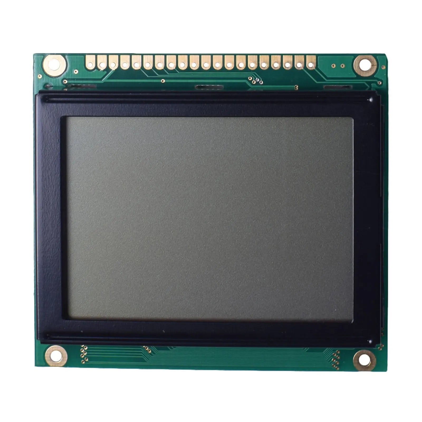
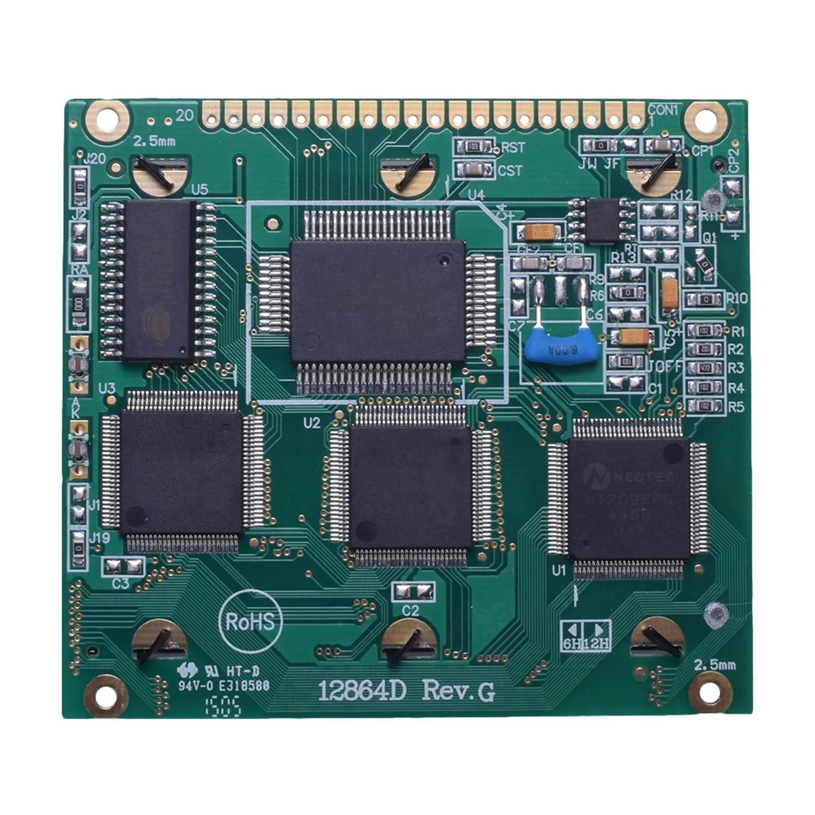

128x64 LCD Graphic Display 3.0" - MCU
- 💹 Enjoy a 20% discount for orders over 500
- 📉 A 15% discount is available for orders ranging from 200 to 499
- 🎁 A 10% discount is available for orders ranging from 50 to 199
- 🎁 A 5% discount is available when ordering 10-49
Interested in customizing this product? Get in touch with us.
Order samples, immediate delivery.
Factory bulk lead time: 3 weeks.
128x64 LCD Graphic Display 3.0" - MCU
- 💹 Enjoy a 20% discount for orders over 500
- 📉 A 15% discount is available for orders ranging from 200 to 499
- 🎁 A 10% discount is available for orders ranging from 50 to 199
- 🎁 A 5% discount is available when ordering 10-49
Resources & Downloads
128 × 64 monochrome graphic LCD Display 3.0" - MCU
DM-LCD12864-459 is a 128 × 64 monochrome graphic LCD module with an FSTN positive transflective display, white LED backlight, RA6963 controller, and an 8080-series 8-bit parallel MPU interface.
The module uses a 78.0 × 70.0 × 14.3 mm maximum outline and a 20-pin through-hole connection. Its operating range is -20°C to +70°C, with storage from -30°C to +80°C.

Verified Technical Specifications
Core product values below follow the DM-LCD12864-459 module datasheet.
| Parameter | Specification |
|---|---|
| Resolution | 128 × 64 pixels |
| Display Mode | FSTN positive, transflective |
| View Direction | 6:00 |
| Module Dimension | 78.0 × 70.0 × 14.3 mm maximum |
| Power Supply | 5.0 V nominal |
| Backlight | White LED |
| Interface | Parallel MPU interface |
| Controller IC | RA6963 |
| Operation Temperature | -20°C to +70°C |
| Storage Temperature | -30°C to +80°C |
| Weight | 77.5 g |
Mechanical and Optical Details
The mechanical drawing defines the enclosure window, mounting pattern, pin spacing, and maximum installed depth.
Viewing Area
62.0 × 44.0 mm.
Active Area
56.3 × 38.38 mm.
Viewing Direction
6:00, with published typical viewing angles of 30° top, 60° bottom, and 45° left/right.
Response Time
300 ms typical and 400 ms maximum at 25°C under the optical test conditions listed in the module datasheet.
Contrast Ratio
5:1 under the optical test conditions listed in the module datasheet.
Mounting and Header
Four 2.5 mm plated-through mounting holes and a 20-position, 2.54 mm pitch through-hole interface footprint.
Luminance note: The published 460 cd/m² minimum and 580 cd/m² typical values are specified for the backlight unit without the LCD. They are not finished on-screen luminance values.
Electrical and Backlight Requirements
Logic power and LED backlight power are specified separately and should be designed as separate loads.
| Electrical Item | Published Value |
|---|---|
| Logic Supply Range | 4.5 V to 5.5 V |
| Logic Supply Current | 11 mA minimum, 12 mA typical, 13 mA maximum at VDD = 5.0 V |
| Low-Level Input | 0 V to 0.15 × VDD |
| High-Level Input | 0.8 × VDD to VDD |
| Low-Level Output | 0 V to 0.3 V |
| High-Level Output | VDD - 0.3 V to VDD |
| Backlight Supply | 3.4 V minimum, 3.5 V typical, 3.6 V maximum |
| Backlight Current | 64 mA typical, 80 mA maximum |
The 12 mA typical figure applies to the logic circuit at 5.0 V. Total system power must also include the separate white LED backlight load.
20-Pin 8080 Parallel MPU Interface
The module connects through an 8-bit parallel data bus with separate read, write, chip-enable, command/data, reset, font-select, power, contrast, and backlight connections.
Interface Summary
Use the module datasheet pin order for PCB release. The RA6963 controller guide explains controller behavior, while the module datasheet controls the final 20-pin assignment, supply, backlight, and mechanical connection.
The drawing specifies a 2.54 mm pitch across 20 plated-through positions.
Power and Contrast
VEE, VSS, VDD, and Vo provide negative-voltage output, ground, logic power, and LCD drive-voltage adjustment.
Control Signals
/WR, /RD, /CE, C/D, and /RESET control write, read, chip enable, command/data selection, and initialization.
8-Bit Data Bus
DB0 through DB7 carry command, status, text, and graphic data between the host and RA6963.
Font Selection
FS high selects a 6 × 8 font. FS low selects an 8 × 8 font.
LED Backlight
Pin 19 is K for backlight negative. Pin 20 is A for backlight positive.
Reset and Status
After power-up, hold reset low for at least five oscillation clocks. Check controller status before data or command transfers.
RA6963 Functions Used by This Module
The RA6963 supports text, graphic, and text-and-graphic display modes through an 8080-series 8-bit MPU interface.
Text and Graphics
Text, graphic, and text-and-graphic modes are available through the RA6963 command set.
Built-In Character ROM
The RA6963 includes a 256-word character generator ROM for ASCII, Japanese, and numeric characters in text mode.
Display Attributes
Controller functions include reverse display, blinking, cursor control, screen copy, and bit set/reset operations.
Display Memory
The module block diagram identifies 32 KB SRAM. The controller specification supports up to 64 KB external display SRAM, which is a controller limit rather than the installed module memory.
Address Mapping
Text home, graphic home, text area, graphic area, cursor, and address-pointer commands define how firmware maps display memory.
Contrast Adjustment
The module block diagram shows external Vo adjustment using a 10 kΩ or 20 kΩ variable resistor arrangement.
Operating and Reliability Conditions
The module datasheet lists the following environmental and endurance test conditions. Final equipment qualification should be completed for the intended application and operating environment.
High-temperature storage: 80°C for 200 hours.
Low-temperature storage: -30°C for 200 hours.
High-temperature operation: 70°C for 200 hours.
Low-temperature operation: -20°C for 200 hours.
Humidity condition: 60°C, 90% RH, 96 hours under the listed no-load condition.
Thermal shock: -20°C to +70°C for 10 cycles.
Static-electricity condition: The datasheet lists 800 V with a 1.5 kΩ / 100 pF test network, applied once to the terminal. This is a component test condition, not a system-level ESD protection rating.
Integration Notes
Power Planning
Size the design for both the logic current and the separate LED backlight current. Do not use the 12 mA logic figure as the complete module load.
Timing Review
Minimum published values include 100 ns C/D setup, 10 ns C/D hold, 80 ns control pulse width, 80 ns data setup, and 40 ns data hold.
Read Access
The module datasheet lists a 150 ns maximum access time and an output hold range of 10 ns minimum to 50 ns maximum.
Contrast Setting
Adjust Vo for the final enclosure, viewing direction, temperature range, and required contrast. Follow the module block diagram for the external adjustment network.
Mechanical Release
Use the 78.0 × 70.0 mm outline, 14.3 mm maximum depth, viewing area, mounting holes, and 20-pin footprint together when designing the enclosure and PCB.
Touch Configuration
No touch-panel specification is provided in the supplied module or controller documents. Treat this model as non-touch unless a separate configuration is confirmed before ordering.
Common Questions
Does the module use a serial interface?
No. DM-LCD12864-459 uses an 8-bit parallel MPU interface with DB0-DB7 and separate read, write, chip-enable, command/data, and reset signals.
Is the logic supply current 12 mA for the complete display?
No. The 12 mA typical value applies to the logic circuit at 5.0 V. The white LED backlight is specified separately at 64 mA typical and 80 mA maximum.
Is 580 cd/m² the visible screen luminance?
No. The datasheet labels 580 cd/m² typical as luminance without the LCD. Finished screen luminance is not specified as the same value.
Does the module contain 64 KB display RAM?
The module block diagram identifies 32 KB SRAM. The RA6963 controller can address up to 64 KB external display SRAM, but that controller maximum is not the installed memory of this module.
Which built-in font sizes are available?
The module FS pin selects 6 × 8 characters when high and 8 × 8 characters when low.
What should be confirmed before PCB release?
Confirm the 20-pin order, 2.54 mm pitch, logic and backlight supplies, Vo contrast network, reset behavior, timing values, mounting pattern, and final mechanical drawing.
Download Official Technical Documents
Review the product datasheet for dimensions, pin assignment, electrical limits, optical values, timing, and reliability conditions. Use the RA6963 controller specification for firmware functions, status handling, memory mapping, and command definitions.