









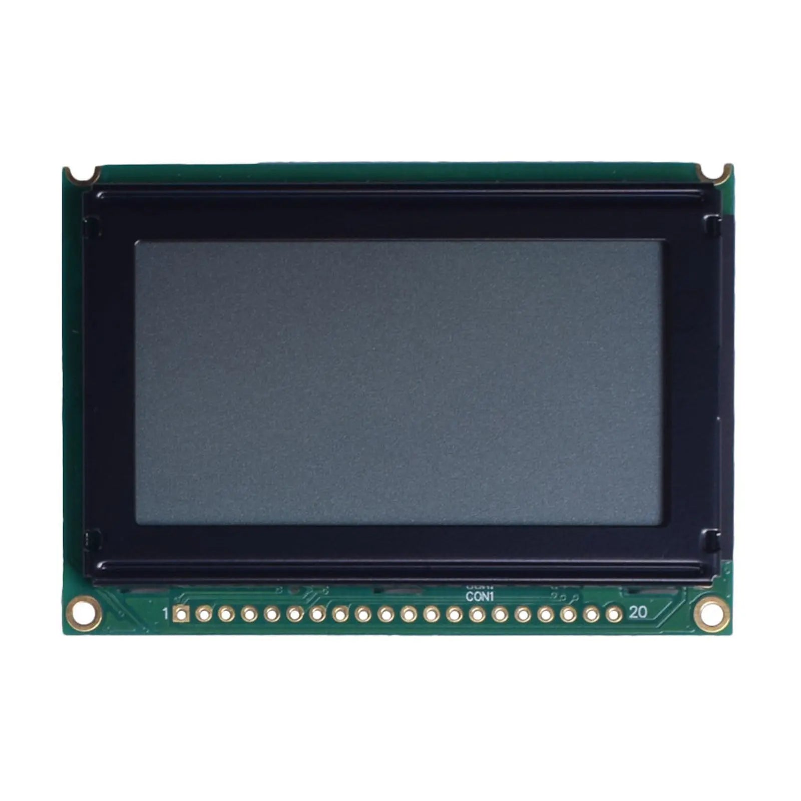
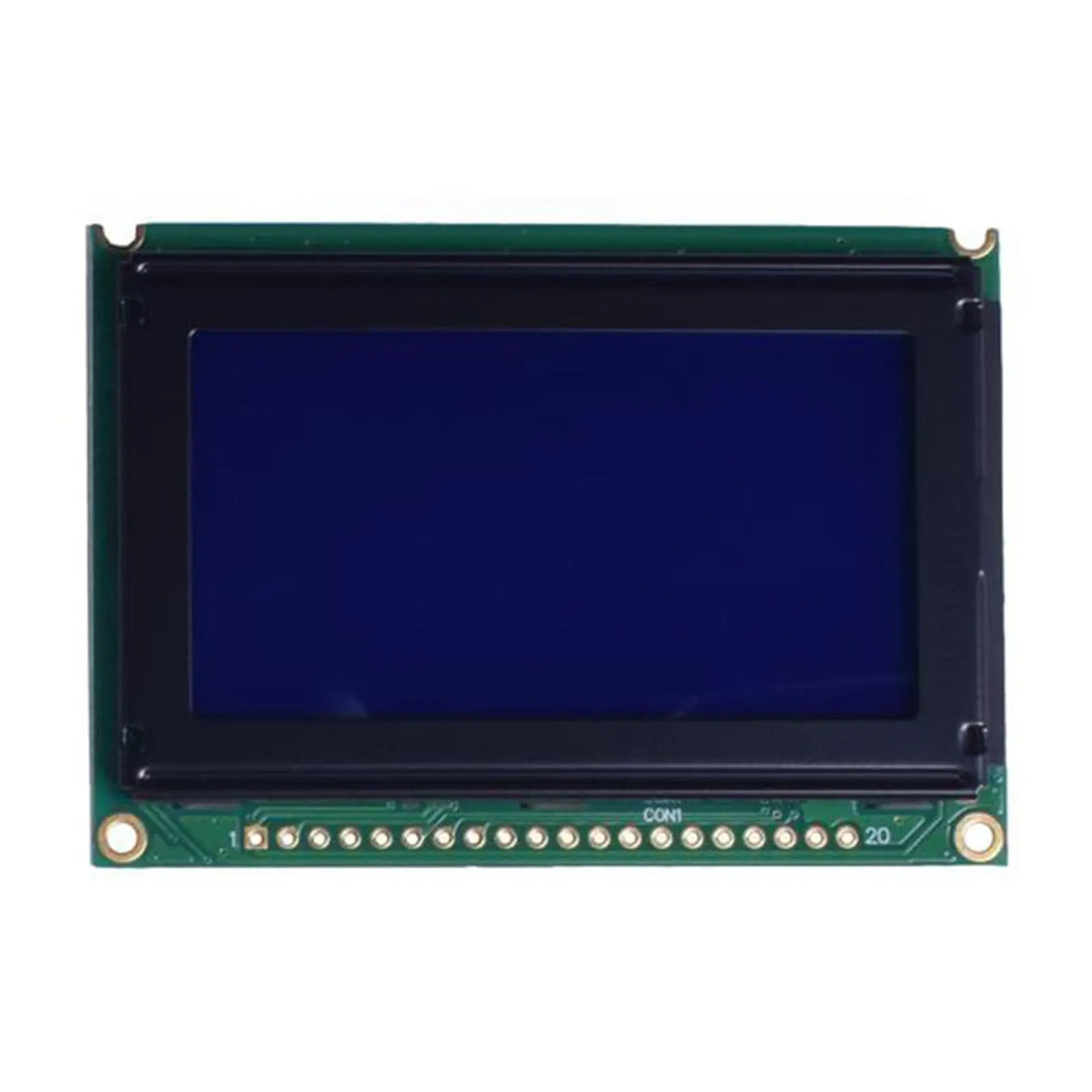
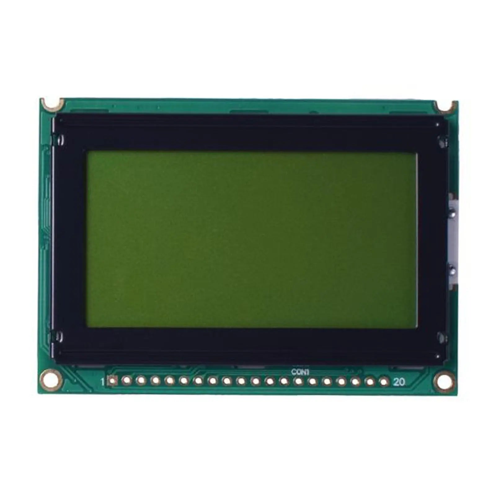

128x64 LCD Graphic Display 2.62" - MCU
- 💹 Enjoy a 20% discount for orders over 500
- 📉 A 15% discount is available for orders ranging from 200 to 499
- 🎁 A 10% discount is available for orders ranging from 50 to 199
- 🎁 A 5% discount is available when ordering 10-49
Interested in customizing this product? Get in touch with us.
Order samples, immediate delivery.
Factory bulk lead time: 3 weeks.
128x64 LCD Graphic Display 2.62" - MCU
- 💹 Enjoy a 20% discount for orders over 500
- 📉 A 15% discount is available for orders ranging from 200 to 499
- 🎁 A 10% discount is available for orders ranging from 50 to 199
- 🎁 A 5% discount is available when ordering 10-49
Resources & Downloads
DM-LCD12864-456 Technical Overview
DM-LCD12864-456 is a 128×64 FSTN positive transflective graphic LCD module with a parallel MPU interface, a 5.0 V nominal logic supply, and NT7108 controller architecture.
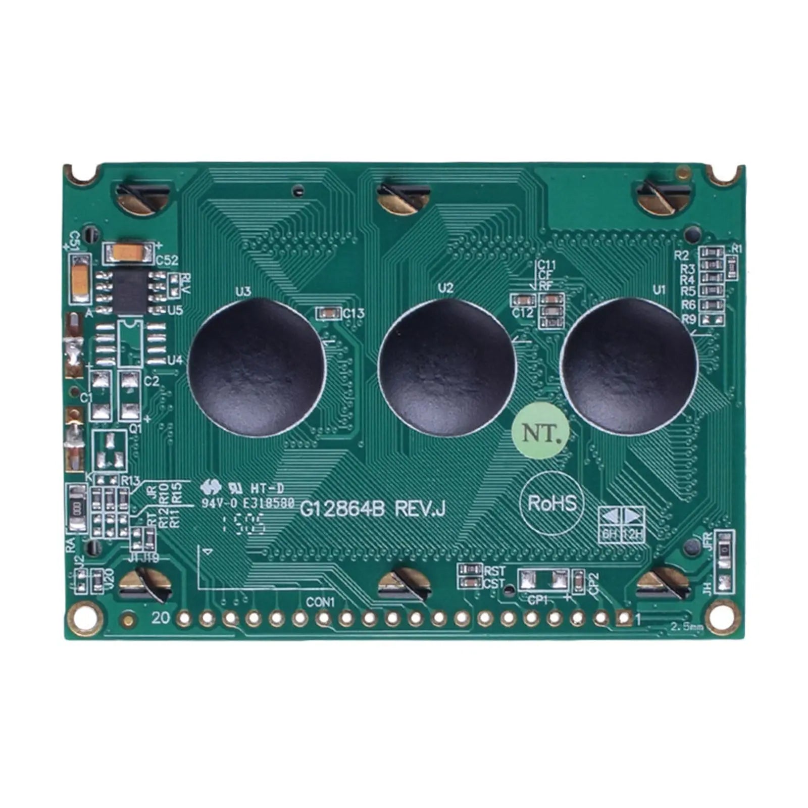
The 20-pin interface provides an 8-bit data bus, separate chip-select inputs for the two 64-column display sections, read/write control, data/instruction control, enable, reset, contrast adjustment, negative voltage output, and LED backlight connections.
Document basis: The values below are taken from the DM-LCD12864-456 module datasheet, its mechanical drawing, and the NT7108 driver IC datasheet. Use the latest datasheet for the exact ordered SKU before PCB, enclosure, or firmware release.

Verified Technical Specifications
These published values apply to DM-LCD12864-456. For DM-LCD12864-457 or DM-LCD12864-458, review the corresponding model datasheet before approving optical appearance, backlight characteristics, or production specifications.
| Parameter | Specification |
|---|---|
| Resolution | 128 × 64 dots |
| Display Mode | FSTN Positive, Transflective |
| Module Dimensions | 75.0 × 52.7 × 8.9 mm (MAX) |
| Controller IC | NT7108 |
| Interface | Parallel MPU Interface |
| Power Supply | 5.0 V (4.5-5.5 V range) |
| View Direction | 6:00 o'clock |
| Operating Temperature | -20°C to +70°C |
| Storage Temperature | -30°C to +80°C |
| Weight | 35.5 g |
| Backlight Type | White LED |
| Backlight Voltage | 3.4-3.6 V (Typical 3.5 V) |
| Backlight Current | 43.2-60 mA (Typical 48 mA) |
| Contrast Ratio | 5:1 typical |
| Response Time | 300 ms typical, 400 ms maximum at 25°C |
Mechanical Details
The mechanical drawing defines the module outline, viewing window, active pixel area, mounting features, and 20-pin through-hole connection. All dimensions below are in millimeters.
Parallel MPU Interface and Pin Functions
The module uses an 8-bit parallel data bus. CS1 selects columns 1-64 and CS2 selects columns 65-128, allowing firmware to address the left and right display sections separately.
Host Connection Requirements
Use the module pin table and timing diagram when designing the host connection. The interface supports both display-data writes and display-data reads through DB0-DB7.
At VDD = 5.0 V, the minimum high-level input voltage is 0.7 × VDD, equal to 3.5 V. A direct 3.3 V GPIO connection therefore does not meet the published minimum threshold. Use suitable level translation or another verified interface solution.
Electrical and Optical Details
Logic and Backlight Supply
Logic supply: 4.5-5.5 V, 5.0 V typical. Supply current is 3.0 mA minimum, 4.0 mA typical, and 5.0 mA maximum at VDD = 5.0 V.
White LED backlight: 3.4-3.6 V and 43.2-60 mA, with 3.5 V and 48 mA listed as typical values.
Published Optical Values
Viewing angles: 30° top, 60° bottom, 45° left, and 45° right.
Response and contrast: 300 ms typical response time, 400 ms maximum at 25°C, with a typical contrast ratio of 5:1.
Backlight-only luminance: 416 cd/m² minimum and 520 cd/m² typical, measured without the LCD. This is not the front-of-display luminance of the assembled module.
NT7108 Driver and Firmware Integration
The module block diagram shows two NT7108 64-channel segment-driver ICs. Each IC controls one 64-column half and provides 512 bytes of display RAM, for 1024 bytes across the complete 128×64 display.
Display Addressing
Firmware can set the Y address, X page address, and display start line. The Y address automatically increments after display-data read or write operations.
Read and Write Control
The interface supports status read, display-data write, and display-data read. Check the busy status before sending a new instruction when required by the firmware sequence.
Published MPU Timing
The module datasheet specifies a 1000 ns minimum E cycle and 450 ns minimum high and low enable widths. Apply the complete setup, hold, and delay limits from the timing table.
Reliability and Operating Conditions
The DM-LCD12864-456 datasheet publishes the following environmental and endurance test conditions. These values support engineering review but do not replace validation in the final enclosure and operating system.
Published Test Conditions
Review temperature range, humidity exposure, thermal cycling, vibration, and static-electricity conditions against the final product requirement before sample approval.
Engineering Notes Before Ordering
Confirm the Exact SKU
DM-LCD12864-456, DM-LCD12864-457, and DM-LCD12864-458 are separate model documents. Match the quotation, sample label, purchase order, and datasheet before production release.
Approve the Final Window
Evaluate viewing direction, contrast, reflected-light readability, backlight appearance, bezel opening, and window tint using a sample in the intended enclosure.
Validate the Host Design
Confirm logic thresholds, contrast circuit, backlight current control, reset behavior, bus timing, chip-select handling, and display-RAM addressing before releasing the PCB and firmware.
Common Questions
Does the module use an 8-bit parallel interface?
Yes. DB0-DB7 form the 8-bit data bus. The host also controls CS1, CS2, R/W, D/I, E, and /RST.
Can it connect directly to a 3.3 V microcontroller?
Do not assume direct compatibility. At a 5.0 V module supply, the specified high-level input threshold is 0.7 × VDD. Verify the host output level and use level translation where required.
Is 520 cd/m² the finished LCD brightness?
No. The datasheet labels 520 cd/m² as a typical luminance value measured without the LCD. The front-of-display luminance of the assembled module will be lower.
How are the 128 columns addressed?
CS1 selects columns 1-64 and CS2 selects columns 65-128. Firmware writes to each 64-column section through the shared parallel data and control lines.
Is a touch panel included?
No touch-panel specification is provided in the supplied module documents. Treat the product as a non-touch graphic LCD unless a separate touch solution is confirmed before ordering.
Which document controls the final design?
Use the latest datasheet and mechanical drawing for the exact ordered module SKU. Use the NT7108 document for driver IC behavior, commands, and RAM details, not as a replacement for the module-level specification.
Download Official Datasheets
Use the exact module datasheet to confirm dimensions, pin assignments, electrical limits, optical values, reliability conditions, and integration requirements. The NT7108 document provides driver-IC command and memory details.