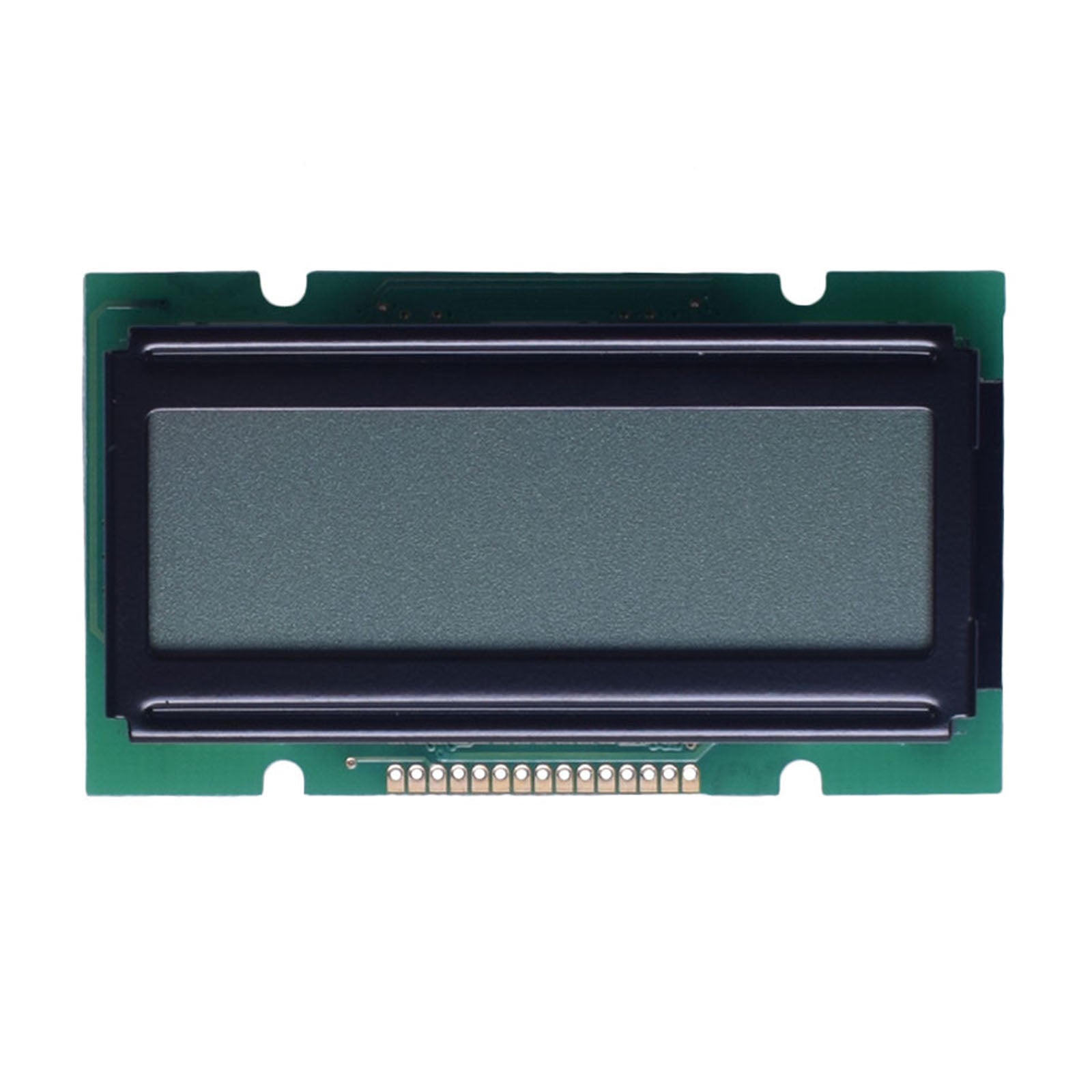
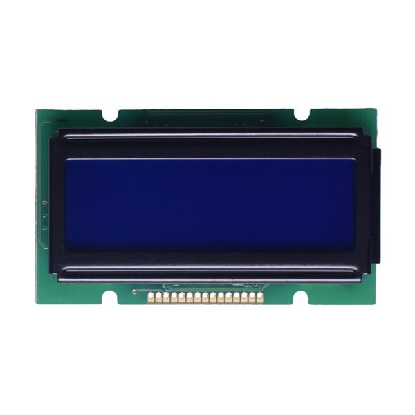
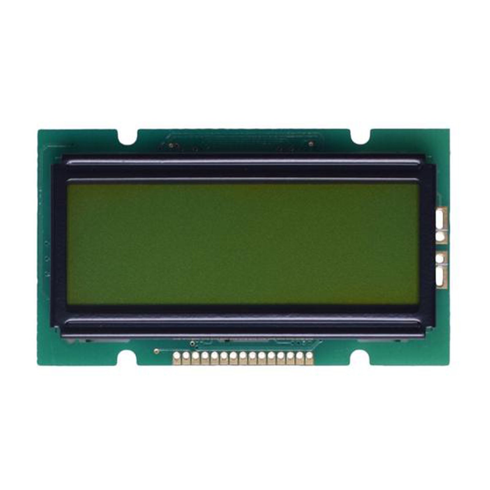
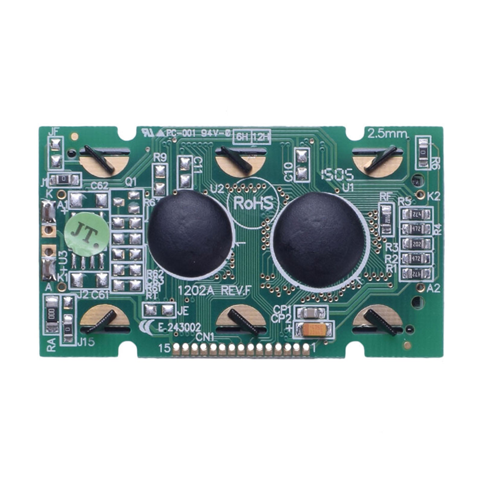
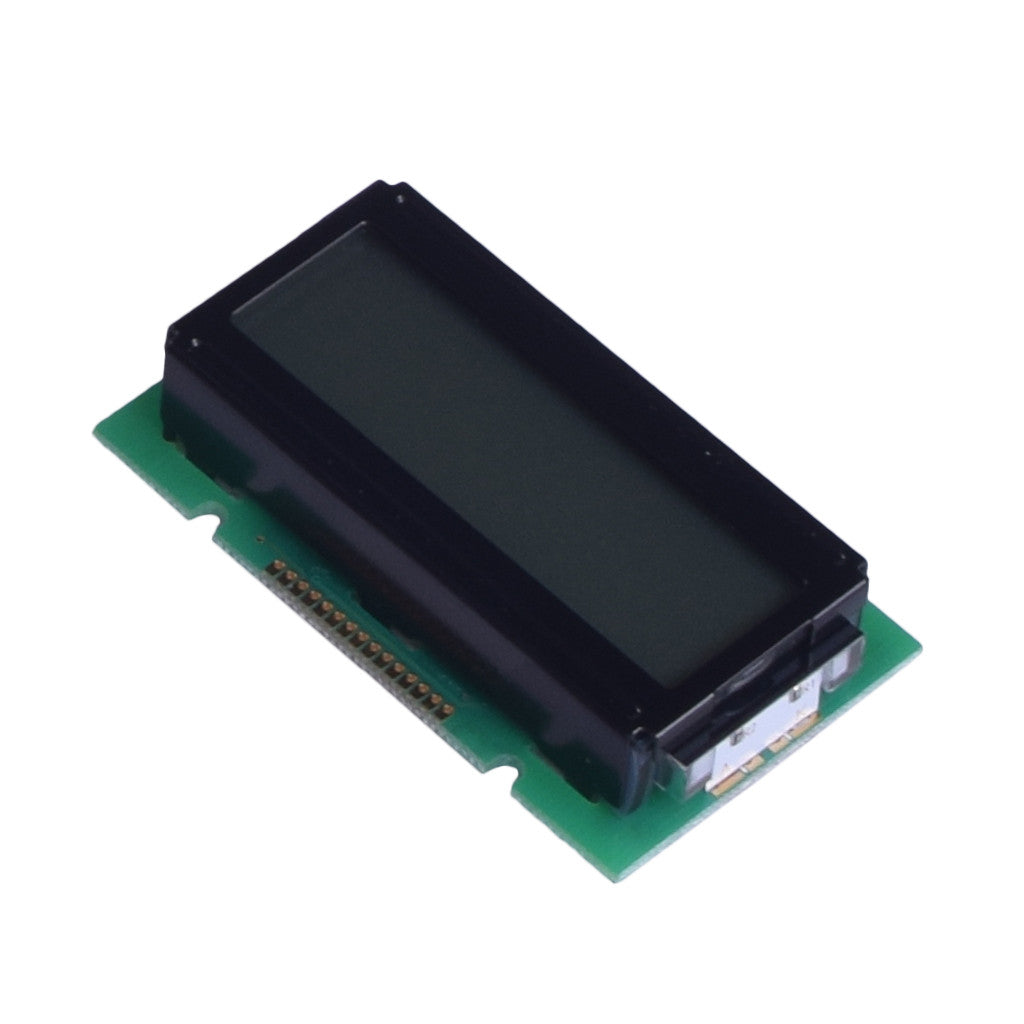
12×2 Character LCD Module with ST7066U and 6800-Series MPU Interface
DM-LCD1202-418, DM-LCD1202-419, and DM-LCD1202-420 are 12-character by 2-line LCD modules developed around the ST7066U dot-matrix LCD controller. The three variants share the same mechanical outline, 5.0 V nominal logic supply, 6800-series parallel MPU interface, 1/16 duty operation, and 6:00 viewing direction.
The variants differ in LCD mode, panel color, backlight color, optical performance, backlight electrical requirements, and weight. Select the datasheet that matches the required gray, blue, or yellow-green version before completing the electrical and mechanical design.
12×2 CharactersTwo-line text display with a 5×8 dot character format.
ST7066UIntegrated dot-matrix LCD controller with 4-bit and 8-bit MPU modes.
55.7×32.0 mmShared module outline with a maximum specified depth of 14.5 mm.
Verified Technical Specifications
The specifications below consolidate the shared mechanical, controller, interface, electrical, and environmental data stated in the three official module datasheets. Variant-dependent values are separated in the following section.
Parameter
Verified Specification
Product Models
DM-LCD1202-418, DM-LCD1202-419, and DM-LCD1202-420
Display Format
12 characters × 2 lines
Character Format
5×8 dots in two-line mode
Controller IC
ST7066U
Interface
6800-series parallel MPU interface
Bus Modes
4-bit mode using DB4 to DB7, or 8-bit mode using DB0 to DB7
Logic Supply Voltage
4.5 V minimum, 5.0 V typical, 5.5 V maximum
Digital Operating Current
1.2 mA typ. at VDD = 5.0 V
Input Low Voltage
VSS to 0.6 V
Input High Voltage
0.7 × VDD to VDD
Output Low Voltage
0.4 V maximum
Output High Voltage
3.9 V minimum
Module Outline
55.7 ± 0.5 mm × 32.0 ± 0.5 mm × 14.5 mm maximum
Viewing Area
46.0 mm × 14.5 mm
Active Area
37.85 mm × 11.7 mm
Viewing Direction
6:00
Duty Cycle
1/16
Interface Pins
15 pins: VSS, VDD, VO, RS, R/W, E, DB0 to DB7, and backlight anode A
Pin Pitch
1.27 mm across the 15-pin row
Operating Temperature
-20°C to +70°C, listed as absolute maximum limits
Storage Temperature
-30°C to +80°C, listed as absolute maximum limits
Response Time at 25°C
300 ms typical, 400 ms maximum for rise time plus fall time
Touch Function
No touch controller or touch interface is specified in the supplied module datasheets
Variant Comparison
Optical values, backlight requirements, LCD mode, and module weight are not identical across the three color options. Use the values for the exact SKU being evaluated.
418
Gray FSTN Positive
DM-LCD1202-418 Transflective mode White LED backlight
Weight23.4 g
Backlight Voltage3.4 V min., 3.5 V typ., 3.6 V max.
Backlight Current32 mA typ., 40 mA max.
Contrast Ratio5
Viewing AnglesTop 30°, bottom 60°, left/right 45°
Luminance Reference840 min., 1050 typ. cd/m², measured without LCD
419
Blue STN Negative
DM-LCD1202-419 Transmissive mode White LED backlight
Weight23.4 g
Backlight Voltage3.4 V min., 3.5 V typ., 3.6 V max.
Backlight Current16 mA min., 20 mA typ., 30 mA max.
Contrast Ratio5
Viewing AnglesVertical 20° to 40°, horizontal -30° to +30°
Luminance120 min., 150 typ. cd/m²
420
Yellow-Green STN Positive
DM-LCD1202-420 Transflective mode Yellow-green LED backlight
Weight17.3 g
Backlight Voltage4.0 V min., 4.2 V typ., 4.7 V max.
Backlight Current30 mA min., 40 mA typ., 48 mA max.
Contrast Ratio3
Viewing AnglesTop 20°, bottom 40°, left/right 30°
Luminance Reference480 min., 600 typ. cd/m², measured without LCD
Controller and MPU Interface
The ST7066U accepts either one 8-bit transfer or two 4-bit transfers. In 4-bit mode, DB4 to DB7 carry the data and DB0 to DB3 are not used for transfer.
6800 MPU timing4-bit bus8-bit busRead and write
Power and ContrastPin 1 is VSS, pin 2 is VDD, and pin 3 is VO for the variable LCD operating voltage used in contrast-bias adjustment.
Control SignalsRS selects display data or instruction code, R/W selects read or write operation, and E is the chip-enable signal.
Data BusDB0 to DB7 form the 8-bit data bus. In 4-bit mode, each byte is transferred as two nibbles through DB4 to DB7.
Backlight PinPin 15 is listed as the backlight positive connection. Backlight voltage and current must be selected from the exact variant datasheet.
Timing ReferenceMinimum enable-cycle time is 1200 ns, minimum enable-pulse width is 140 ns, and minimum write-data setup time is 40 ns.
Electrical Design Limits
Use the module limits rather than the standalone controller operating range when designing the host interface. The module datasheets specify a 5.0 V nominal logic supply and variant-specific LED requirements.
Logic Interface Reference
These limits are common to the three module variants.
VDD Supply
4.5 V minimum → 5.0 V typical → 5.5 V maximum
Logic High Input
VIH = 0.7 × VDD minimum
Logic Low Input
VIL = 0.6 V maximum
Operating Current
IDD = 1.2 mA at VDD = 5.0 V
3.3 V Host Review
At VDD = 5.0 V, the guaranteed high-input threshold is 3.5 V. A 3.3 V host may not meet the specified VIH margin, so verify the interface or use suitable level translation.
Backlight Selection
The gray and blue variants use a white LED backlight. The yellow-green variant uses a different LED voltage range and should not be substituted without reviewing the drive circuit.
Contrast Bias
VO is specified as a variable LCD operating-voltage input. Include an adjustable or validated bias arrangement during prototype evaluation.
Mechanical Integration Details
Review the complete drawing before PCB release. The outer outline, viewing window, active character area, pin location, mounting features, and side-view depth all affect the enclosure and board layout.
55.7 ± 0.5 mmOverall module width
32.0 ± 0.5 mmOverall module height
46.0 × 14.5 mmSpecified viewing area
37.85 × 11.7 mmSpecified active character area
14.5 mm Max.Maximum side-view module depth
The drawing shows a 15-position pin row at 1.27 mm pitch and four R1.25 mounting cutouts. Confirm pad geometry, board clearance, display-window alignment, and enclosure tolerance against the official drawing before ordering production quantities.
Selected Datasheet Reliability Conditions
These are stated qualification-test conditions for engineering review. They should not be interpreted as a field-life guarantee or as permission to operate outside the specified temperature limits.
High-Temperature Storage
80°C for 200 hours.
Low-Temperature Storage
-30°C for 200 hours.
Temperature Operation
+70°C for 200 hours and -20°C for 200 hours.
Temperature and Humidity
60°C at 90% RH for 96 hours under the stated no-load condition.
Thermal Shock
-20°C to +70°C for 10 cycles.
Engineering Notes Before PCB Release
The most important interface check is the relationship between the module supply and the host processor's guaranteed logic-high output.
VIH minimum = 0.7 × VDD
With the module operated at VDD = 5.0 V, the specified minimum high-input voltage is 3.5 V. Verify this margin rather than assuming direct compatibility with every 3.3 V controller.
Select the Exact Variant
Confirm the SKU, LCD mode, panel color, backlight color, backlight voltage, backlight current, optical values, and weight before approving the design.
Validate the Power-On Sequence
Follow the official ST7066U initialization sequence and required delays. Do not send normal commands before the controller supply and initialization conditions are satisfied.
Plan VO Adjustment
Pin 3 is a variable LCD operating-voltage input. Evaluate the required contrast-bias arrangement under the intended supply voltage and temperature range.
Check the Backlight Circuit
Use the selected SKU's LED voltage and current limits. Confirm current limiting, thermal conditions, polarity, and the final backlight connection before prototype assembly.
Confirm Mechanical Revision
Use the official drawing for the display window, active area, board outline, mounting cutouts, pin pitch, and maximum depth. Confirm the current revision before tooling.
Confirm Commercial Details
Sample availability, production lead time, packing, lifecycle status, and customization scope should be confirmed with DisplayModule before ordering.
Common Questions Before Sample Evaluation
These answers distinguish shared family characteristics from specifications that depend on the selected color variant.
Can the module operate in 4-bit MPU mode?
Yes. The ST7066U supports 4-bit and 8-bit operation. In 4-bit mode, DB4 to DB7 are used and each byte is transferred in two operations.
Can it be connected directly to a 3.3 V microcontroller?
Direct operation is not guaranteed by the stated input threshold. At a 5.0 V module supply, VIH minimum is 3.5 V. Verify the host output level or use appropriate level translation.
Do all three colors use the same backlight voltage?
No. The gray and blue variants specify a 3.4 to 3.6 V white LED backlight. The yellow-green variant specifies a 4.0 to 4.7 V yellow-green LED backlight.
Are the three variants mechanically interchangeable?
The supplied datasheets state the same module outline and display format. Electrical backlight requirements, optical values, and weight differ, so the complete SKU-specific datasheet must still be reviewed.
Does this LCD include a touch panel?
No touch controller, touch-panel interface, or touch specification is listed in the supplied module datasheets. Confirm separately if an external touch overlay is required.
Which datasheet should be used for PCB and backlight design?
Use DM-LCD1202-418 for gray, DM-LCD1202-419 for blue, and DM-LCD1202-420 for yellow green. Use the ST7066U document for detailed controller instructions and interface behavior.
Is the luminance value identical for all variants?
No. Each variant has its own luminance specification. The gray and yellow-green datasheets identify their values as measurements without the LCD, while the blue datasheet lists a module luminance value.
What should be confirmed before a production order?
Confirm the exact SKU, datasheet revision, logic-level compatibility, backlight drive, VO bias, pin arrangement, mechanical drawing, sample performance, availability, and lead time.
Download Official Datasheet
Select the document that matches the required panel color and SKU. The module datasheets provide dimensions, pin assignments, electrical limits, optical characteristics, timing information, initialization guidance, reliability conditions, and mechanical drawings.