









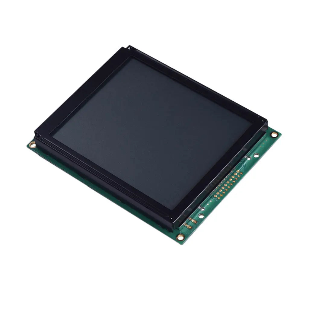
160x128 Graphic LCD 5.12" - MCU
- 💹 Enjoy a 20% discount for orders over 500
- 📉 A 15% discount is available for orders ranging from 200 to 499
- 🎁 A 10% discount is available for orders ranging from 50 to 199
- 🎁 A 5% discount is available when ordering 10-49
Interested in customizing this product? Get in touch with us.
Order samples, immediate delivery.
Factory bulk lead time: 3 weeks.
160x128 Graphic LCD 5.12" - MCU
- 💹 Enjoy a 20% discount for orders over 500
- 📉 A 15% discount is available for orders ranging from 200 to 499
- 🎁 A 10% discount is available for orders ranging from 50 to 199
- 🎁 A 5% discount is available when ordering 10-49
Resources & Downloads
5.12-Inch Graphic LCD Modules with RA6963 Parallel MPU Interface
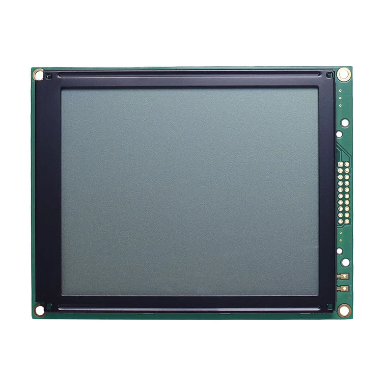
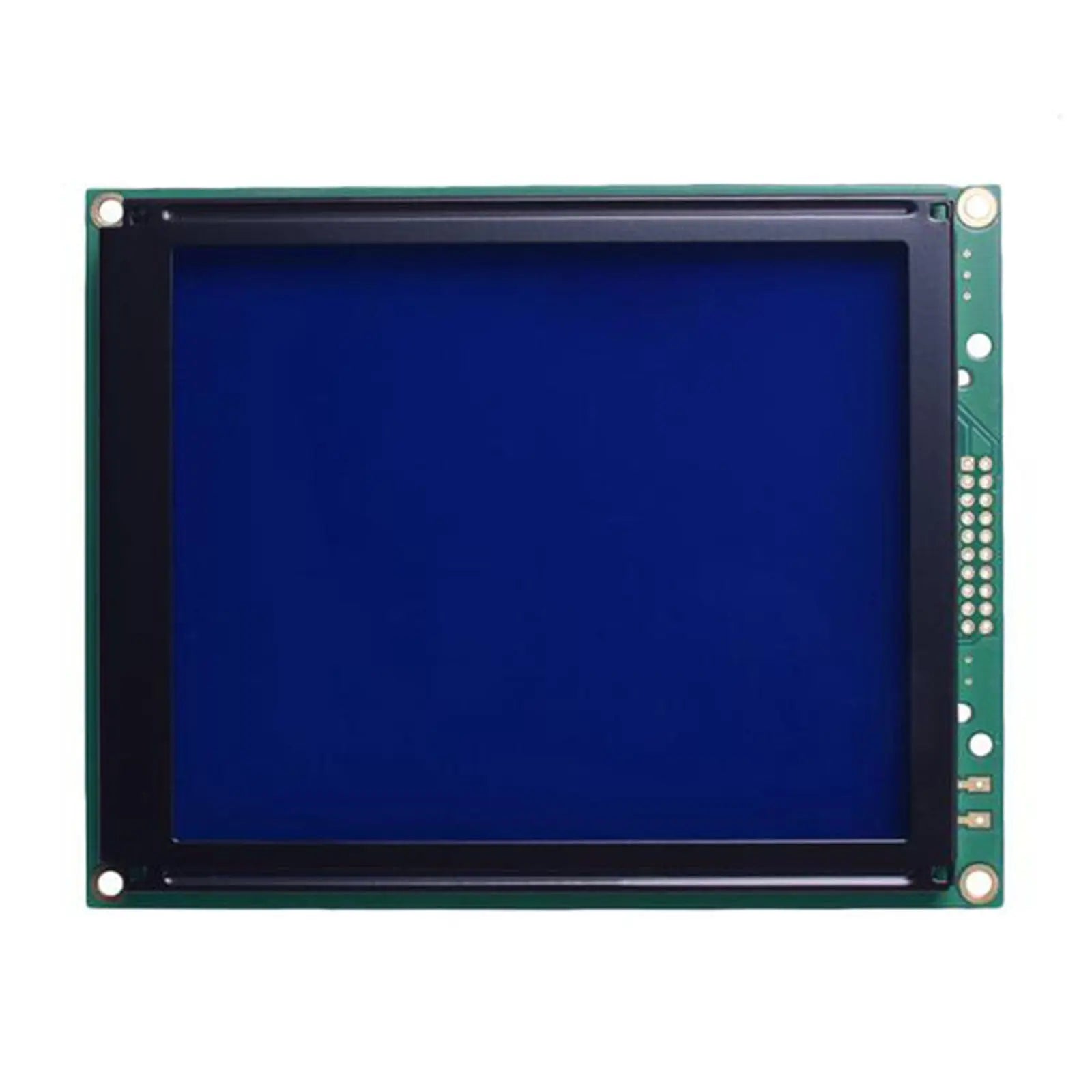
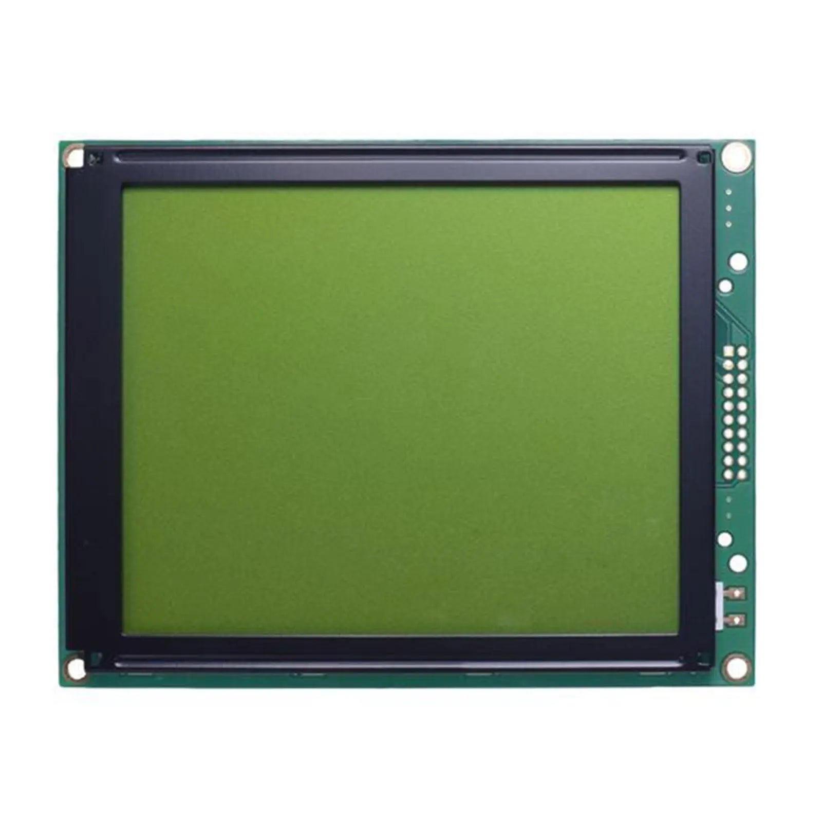
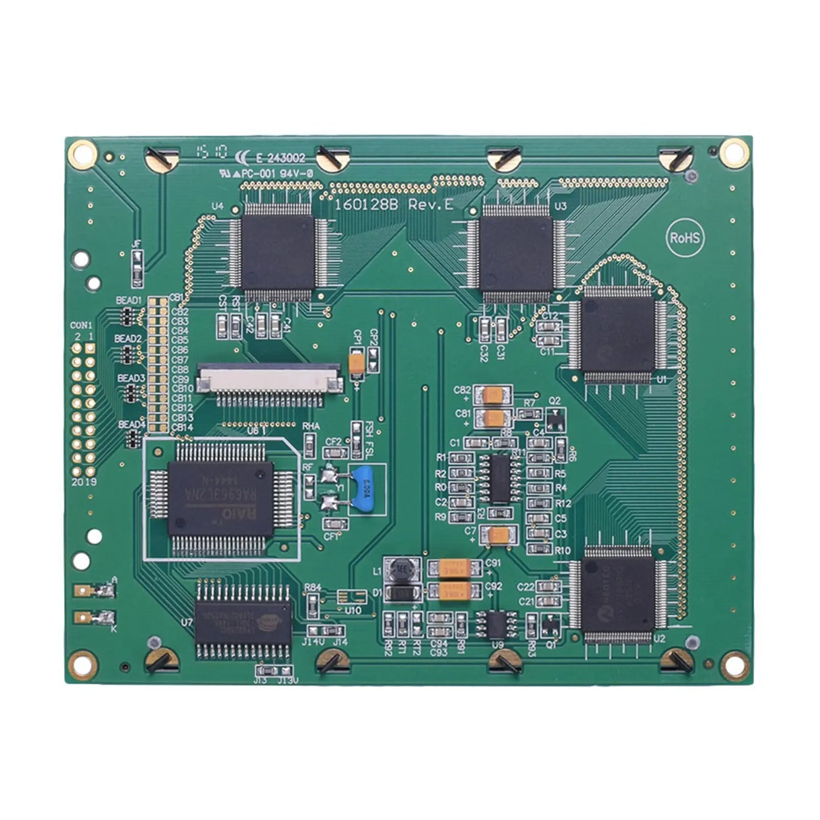
The DM-LCD160128-465, DM-LCD160128-466 and DM-LCD160128-467 are 160×128-dot monochrome graphic LCD modules built around the RA6963 controller and an 8-bit parallel MPU interface. All three models use a 129.0×102.0×16.5 mm maximum module outline, a 1/128 duty cycle and a 6:00 viewing direction.
The models share the same resolution, mechanical format, controller and interface while using different LCD modes, backlight colors, optical values and backlight electrical conditions. The ordered model number should therefore be selected according to the required display appearance and backlight circuit.

Available LCD and Backlight Configurations
The three product variants are mechanically similar but are not optically or electrically identical. Backlight voltage, backlight current, display mode, viewing angles, contrast ratio and module weight vary by model.
FSTN Positive Transflective
Positive FSTN display mode with a white LED backlight.
- Backlight: White LED
- Backlight voltage: 3.4 V minimum, 3.5 V typical, 3.6 V maximum
- Backlight current: 128 mA typical, 160 mA maximum
- Viewing angles: Top 30°, bottom 60°, left 45°, right 45° typical
- Contrast ratio: 5 typical
- Luminance without LCD: 480 cd/m² minimum, 600 cd/m² typical
- Weight: 171.4 g
STN Positive Yellow-Green
Positive STN yellow-green transflective display with a yellow-green LED backlight.
- Backlight: Yellow-green LED
- Backlight voltage: 4.0 V minimum, 4.2 V typical, 4.4 V maximum
- Backlight current: 520 mA minimum, 650 mA typical, 780 mA maximum
- Viewing angles: Top 20°, bottom 40°, left 30°, right 30° typical
- Contrast ratio: 3 typical
- Luminance without LCD: 90 cd/m² minimum, 110 cd/m² typical
- Weight: 169.3 g
STN Negative Blue
Negative STN blue transflective display mode with a white LED backlight.
- Backlight: White LED
- Backlight voltage: 3.4 V minimum, 3.5 V typical, 3.6 V maximum
- Backlight current: 128 mA typical, 160 mA maximum
- Viewing angles: Top 20°, bottom 40°, left 30°, right 30° typical
- Contrast ratio: 3 typical
- Luminance without LCD: 480 cd/m² minimum, 600 cd/m² typical
- Weight: 169.8 g
The luminance values published in the module datasheets are identified as measurements without the LCD. They should not be interpreted as finished on-screen luminance values through the LCD panel, polarizer, enclosure window or cover material.
Verified Technical Specifications
The following values are shared across the DM-LCD160128-465, DM-LCD160128-466 and DM-LCD160128-467 datasheets unless a model-specific difference is stated separately.
| Parameter | Published Specification |
|---|---|
| Product Type | Monochrome graphic LCD module |
| Available Models | DM-LCD160128-465, DM-LCD160128-466 and DM-LCD160128-467 |
| Resolution | 160×128 dots |
| Module Dimension | 129.0×102.0×16.5 mm maximum |
| Viewing Area | 101.0×82.0 mm |
| Active Area | 95.96×76.76 mm |
| Controller IC | RA6963 |
| Interface | Parallel MPU interface with DB0-DB7 8-bit data bus |
| Duty Cycle | 1/128 |
| View Direction | 6:00 |
| Published Power Supply | 5.0 V nominal in the main specification table |
| Logic Supply Range | 3.0 V minimum to 5.5 V maximum |
| Logic Supply Current | 30 mA minimum, 42 mA typical and 50 mA maximum at VDD = 5.0 V |
| Low-Level Input Voltage | 0 V minimum to 0.2×VDD maximum |
| High-Level Input Voltage | 0.8×VDD minimum to VDD maximum |
| Low-Level Output Voltage | 0 V minimum to 0.3 V maximum |
| High-Level Output Voltage | VDD - 0.3 V minimum to VDD maximum |
| Response Time at 25°C | 300 ms typical and 400 ms maximum, specified as rise time plus fall time |
| Operating Temperature | -20°C to +70°C absolute maximum range |
| Storage Temperature | -30°C to +80°C absolute maximum range |
| Connection | 20 through-hole pin positions; pin 20 is identified as no connection |
Mechanical Dimensions and Mounting Details
The supplied mechanical drawing defines the module outline, viewing area, active area, mounting holes and through-hole connection pattern. The principal overall width and height are specified with ±0.5 mm tolerance. The drawing states a general tolerance of ±0.3 mm for dimensions without a separate tolerance.
The connection drawing shows 20 plated through holes with Ø1.0 mm finished holes and Ø2.0 mm pads. The pins are arranged as two 10-position rows with 2.54 mm pitch across each row.
Parallel Interface and Pin Functions
The module uses separate read and write control signals together with an 8-bit bidirectional data bus. The pin definitions below follow the module datasheets.
20-Pin Parallel Connection
The host connection includes frame ground, logic power, contrast control, negative voltage output, read and write controls, controller enable, command/data selection, halt, reset and the DB0-DB7 data bus.
The backlight has model-specific voltage and current requirements and should be driven according to the selected module datasheet.
Published Parallel Timing Characteristics
The timing values apply to the parallel controller interface shown in the module datasheets. Host firmware and hardware should meet the minimum setup, hold and pulse-width conditions.
| Timing Parameter | Published Value |
|---|---|
| C/D Setup Time | 100 ns minimum |
| C/D Hold Time | 10 ns minimum |
| CE, RD and WR Pulse Width | 80 ns minimum |
| Data Setup Time | 80 ns minimum |
| Data Hold Time | 40 ns minimum |
| Read Access Time | 150 ns maximum |
| Output Hold Time | 10 ns minimum and 50 ns maximum |
RA6963 Controller Functions
The RA6963 is a dot-matrix LCD controller identified by RAiO as compatible with the T6963C controller architecture. It provides an 8-bit parallel data bus for connection to an 8080-series MPU interface and supports character, graphic and combined text-and-graphic display modes.
Text and Graphics
Character mode, graphic mode and mixed text-and-graphic display operation are supported by the controller.
Character Generator
The controller includes a 256-word character-generator ROM for basic ASCII, Japanese and numeric characters.
Display Data Access
Supported commands include normal data read and write, automatic data read and write, screen peek, screen copy and bit set or reset.
Text Attributes
Text attribute functions include reverse display, character blink, bold display and display inhibit.
The RA6963 controller documentation describes controller-level functions. The module datasheet remains the applicable source for the module pin assignment, electrical limits, backlight requirements, timing and mechanical dimensions.
Published Environmental and Reliability Test Conditions
The module datasheets list the following environmental and reliability test conditions. These values describe documented module test conditions and are not presented as a product lifetime rating or a system-level regulatory certification.
High-temperature storage: 80°C for 200 hours.
Low-temperature storage: -30°C for 200 hours.
High-temperature operation: 70°C for 200 hours.
Low-temperature operation: -20°C for 200 hours.
High-temperature and humidity condition: 60°C and 90% RH maximum for 96 hours under the no-load condition stated in the datasheet.
Thermal shock: -20°C to +70°C for 10 cycles using the published dwell and transfer sequence.
Vibration condition: 10-55 Hz in the X, Y and Z directions for 16 minutes per direction. The datasheet lists a total fixed amplitude of 15 mm.
Static electricity condition: 800 V with 1.5 kΩ resistance and 100 pF capacitance, applied one time.
Common Questions Before Ordering
What is the difference between the 465, 466 and 467 models?
They share the 160×128 resolution, RA6963 controller, parallel interface, module outline, operating temperature and storage temperature. The LCD mode, backlight color, backlight voltage, backlight current, viewing angles, contrast ratio, luminance-without-LCD value and weight differ by model.
Can the module operate from 5 V logic?
The main specification lists a 5.0 V power supply, while the electrical characteristics specify a VDD logic range from 3.0 V to 5.5 V. Host signal levels must remain within the published input limits relative to the selected VDD.
Do all three models use the same backlight circuit?
No. DM-LCD160128-465 and DM-LCD160128-467 specify a 3.5 V typical white LED backlight at 128 mA typical. DM-LCD160128-466 specifies a 4.2 V typical yellow-green LED backlight at 650 mA typical.
Is the RA6963 compatible with T6963C firmware?
RAiO identifies the RA6963 controller as compatible with the T6963C controller architecture. The host design should still follow the exact module pin assignment, interface timing, display-memory configuration and initialization requirements documented for the selected module.
Is 600 cd/m² the finished display brightness?
No. The applicable datasheets label this value as luminance without the LCD. It is not a published finished on-screen luminance value after the LCD, polarizer and final enclosure window.
What mechanical area should be used for the enclosure window?
The drawing identifies a 101.0×82.0 mm viewing area and a 95.96×76.76 mm active area. The enclosure design should also account for the 129.0×102.0 mm module outline, mounting-hole locations and 16.5 mm maximum depth.
Which document should be used for PCB and firmware integration?
Use the datasheet for the exact ordered module to define dimensions, pin functions, electrical limits, backlight conditions and parallel timing. Use the RA6963 controller documentation for command functions and controller-level programming details.
Download Official Technical Documents
Use the module datasheet for the exact optical variant being ordered. The documents include mechanical dimensions, pin descriptions, electrical characteristics, optical characteristics, interface timing, commands and published reliability conditions.