







Zum Inhalt springen

Warenkorb

Dein Warenkorb ist leer

Weiter einkaufen

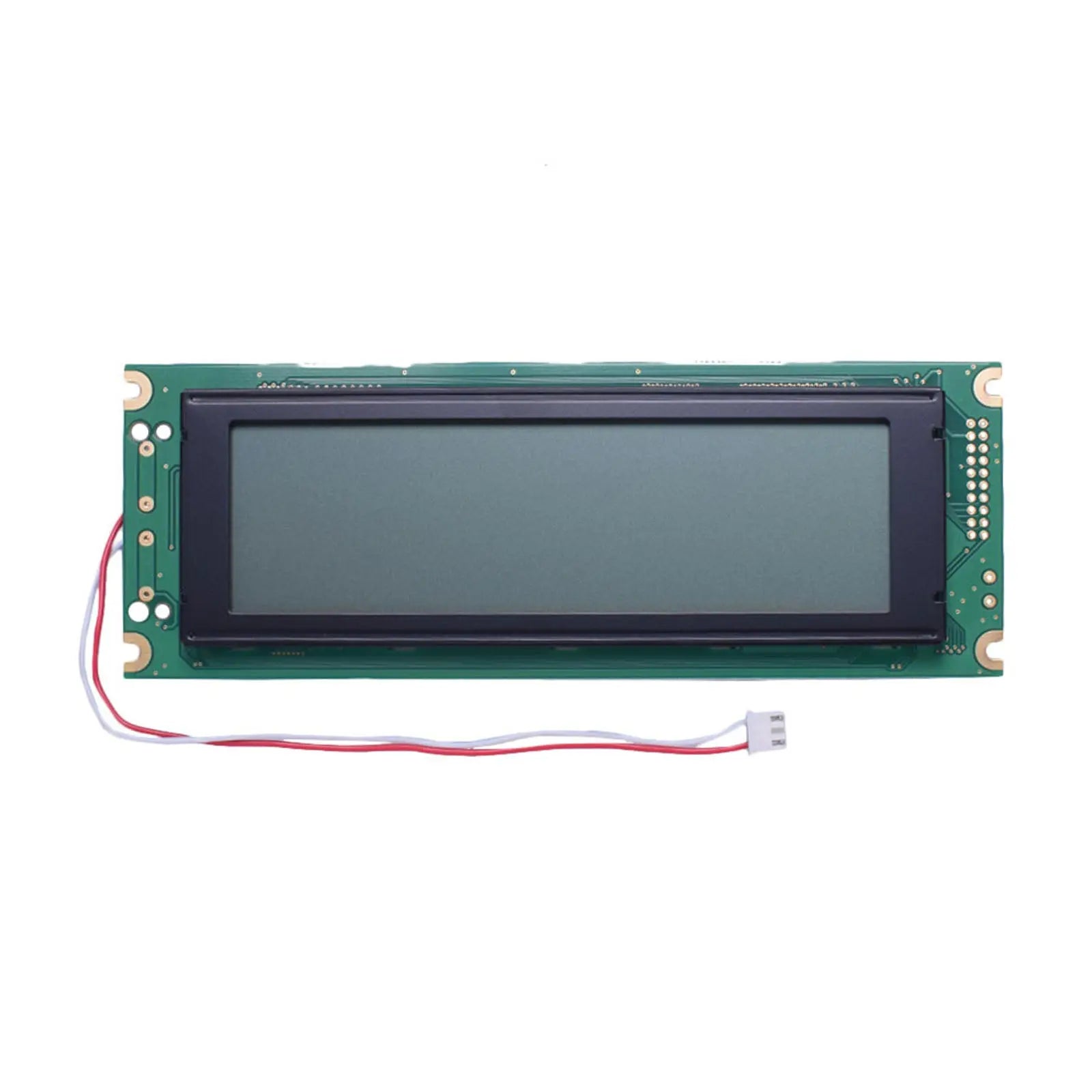
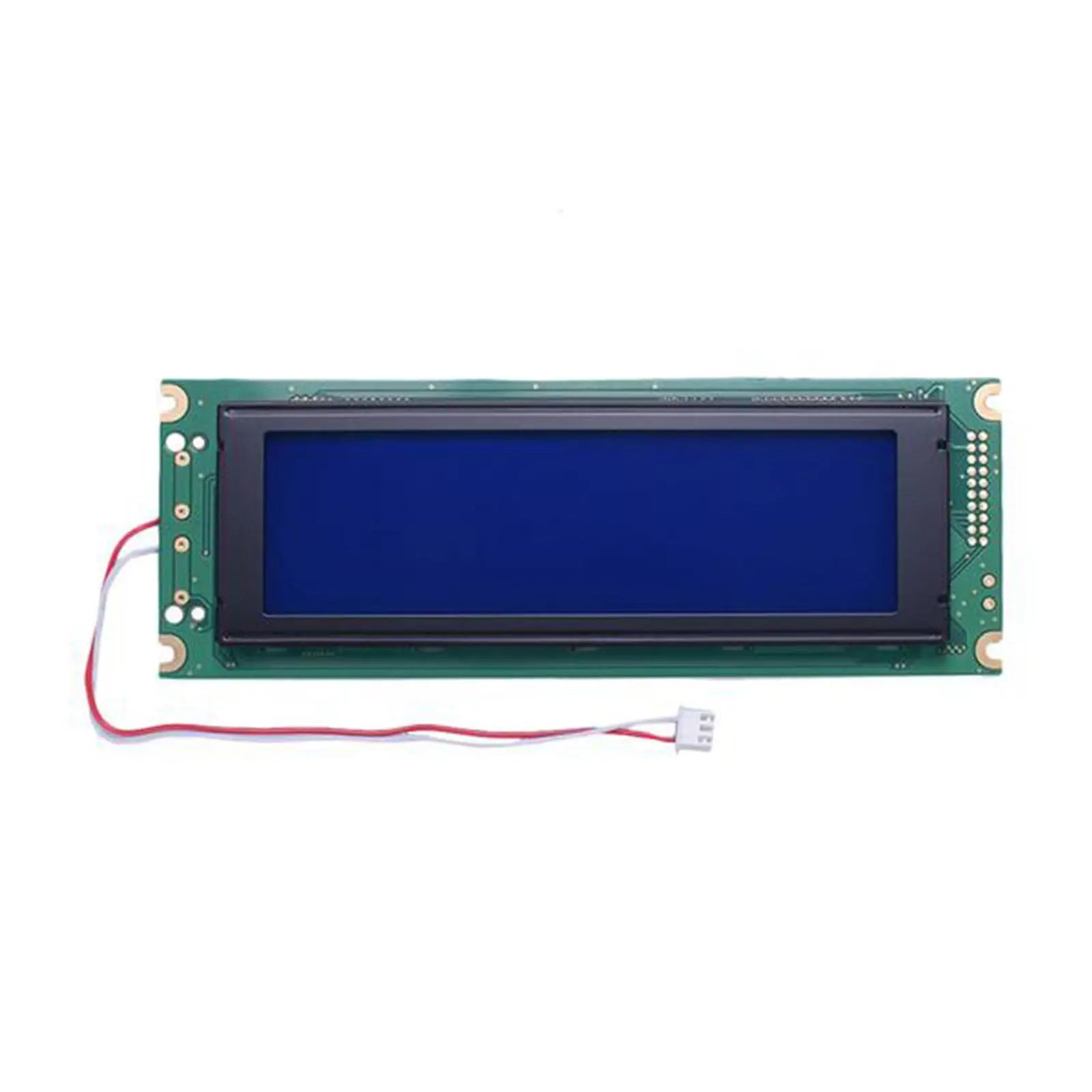
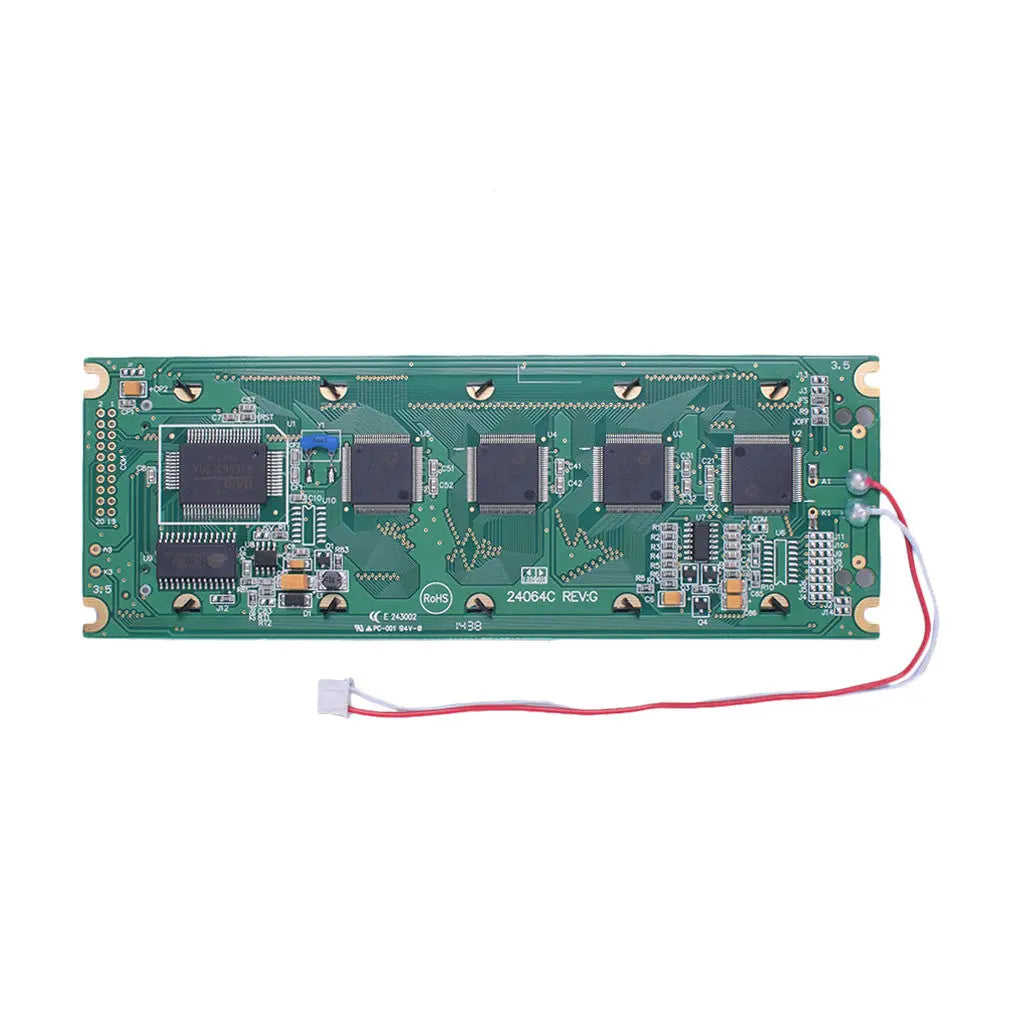
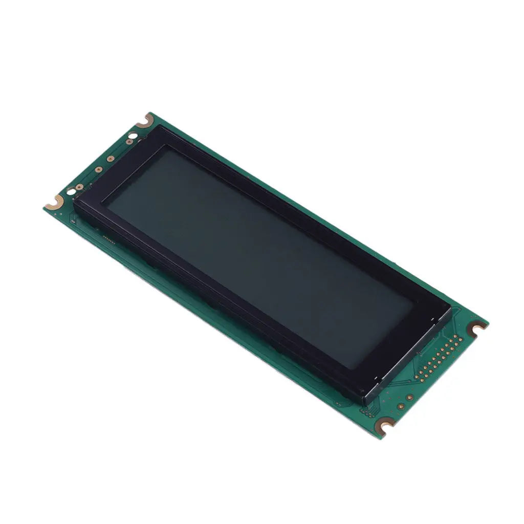
240x64 LCD Graphic 5.46" - MCU

SKU: DM-LCD24064-468
Angebot$75.90
  • 💹 Enjoy a 20% discount for orders over 500
  • 📉 A 15% discount is available for orders ranging from 200 to 499
  • 🎁 A 10% discount is available for orders ranging from 50 to 199
  • 🎁 A 5% discount is available when ordering 10-49

Interested in customizing this product? Get in touch with us.

Order samples, immediate delivery.

Factory bulk lead time: 3 weeks.

Color: Black White

Teilen
5.46-inch 240x64 LCD Graphic display module with MCU interface
240x64 LCD Graphic 5.46" - MCUBlack White Angebot$75.90

Resources & Downloads

DM-LCD320240-479

320×240 Graphic LCD 4.72" Industrial Blue - MCU

DM-LCD320240-479 is a 320×240 monochrome graphic LCD module with an STN negative blue transmissive display, white LED backlight, RA8835 controller, and parallel MPU interface.

The module uses a 1/240 duty drive, a 6:00 viewing direction, a 95.98×71.98 mm active area, and a 139.0×100.0×13.1 mm maximum outline. The published interface supports 8080- and 6800-family host buses through the documented signal configuration.

320×240Graphic pixel matrix
RA8835LCD controller
139.0×100.0 mmModule outline

Document use: Use the DM-LCD320240-479 datasheet for module dimensions, pin assignment, optical data, electrical limits, and environmental conditions. Use the RA8835 specification for controller commands, timing, memory access, and display-control functions.

DM-LCD320240-479 320 by 240 graphic LCD module mechanical dimensions drawing

Verified Technical Specifications

The table lists the published module specifications used for mechanical, optical, electrical, and environmental review.

Parameter Specification
Model DM-LCD320240-479
Display Type Monochrome graphic LCD module
Resolution 320×240 dots
LCD Mode STN negative, blue, transmissive
Viewing Direction 6:00
Duty 1/240
Active Area 95.98×71.98 mm
Viewing Area 104.0×79.3 mm, as shown in the mechanical drawing
Pixel Pitch 0.30×0.30 mm
Module Outline 139.0×100.0×13.1 mm maximum; the drawing specifies ±0.5 mm on the 139.0 mm and 100.0 mm outline dimensions
Backlight White LED
Controller IC RA8835
Host Interface Parallel MPU interface with 8-bit data bus
Supported MPU Families 8080 and 6800 families, according to the module pin table and RA8835 interface specification
Operating Temperature -20°C to +70°C
Storage Temperature -30°C to +80°C

Optical, Electrical and Mechanical Details

These values separate the logic supply, LCD drive requirement, backlight input, and optical test conditions so they can be reviewed independently during PCB and enclosure design.

Separate Power Domains

The 5.0 V value is the typical logic supply and the typical backlight supply. LCD contrast also depends on the VDD-VO drive voltage and the VOP adjustment circuit shown in the module datasheet.

The recommended circuit shows a 10 kΩ to 20 kΩ variable resistor connected between VDD, VO, and VEE for contrast adjustment on the host board.

Logic Supply

VDD-VSS: 4.5 to 5.5 V, 5.0 V typical. Supply current at VDD = 5.0 V is 52.2 mA minimum, 52.4 mA typical, and 52.8 mA maximum.

LCD Drive Voltage

VDD-VO at 25°C: 21.0 to 22.2 V, 21.6 V typical. The host board must provide the documented VOP adjustment circuit.

White LED Backlight

Backlight supply: 4.9 to 5.1 V, 5.0 V typical. Backlight current: 40 to 160 mA, 128 mA typical at 5.0 V.

Optical Values

Contrast ratio: 3:1 typical. Rise time: 200 ms typical, 300 ms maximum. Fall time: 250 ms typical, 350 ms maximum.

Backlight Luminance Test

450 cd/m² minimum and 560 cd/m² typical at ILED = 128 mA. The datasheet identifies this value as luminance measured without the LCD layer.

Specified Viewing Angles

At contrast ratio ≥2: top 20° maximum, bottom 40° maximum, left 30° maximum, and right 30° maximum.

Connector and Parallel Interface Details

The module documentation lists CON1 and CON2 pin arrangements. Review the exact connector option, mating hardware, and host-bus selection before PCB release.

8-Bit Parallel MPU Bus

DB0 through DB7 carry data between the host and the RA8835. WR, RD, CS, A0, and RES provide write/read timing, chip select, command/data selection, and controller reset.

The RA8835 supports 8080- and 6800-family interfaces. On CON2, SEL1 is documented as high for 6800 mode and low for 8080 mode.

The mechanical drawing shows 2.54 mm connector pitch. CON1 is a 20-pin connection and CON2 is an 18-pin connection.

VDD / GND5.0 V logic supply and ground.
VO / VEELCD drive and negative-voltage connections used by the contrast-adjustment circuit.
DB0-DB7Eight parallel data-bus lines.
WR / RD8080 mode: write and read signals. 6800 mode: R/W and enable-clock functions.
CSChip-select input, active low.
A0Selects command/status or display-data access according to the documented read/write state.
RESController reset input, active low.
A / KWhite LED backlight positive and negative terminals provided on CON1.
SEL1CON2 host-family selection: high for 6800 and low for 8080.

RA8835 Controller Functions

The RA8835 specification defines the controller functions available to firmware. The final initialization sequence, display-memory mapping, timing, and screen layout must be validated for the 320×240 module.

Text and Graphics

Supports text, graphics, and combined text/graphics display modes.

Layered Screens

Supports up to three overlapping screens in graphics mode, controlled by firmware and display-memory configuration.

Cursor Control

Provides programmable cursor form, direction, position, and display-layer controls.

Scrolling

Provides horizontal, vertical, on-page, inter-page, and bidirectional scrolling functions.

Published Reliability Test Conditions

The following conditions are listed in the module datasheet for product-level reliability review. They are test conditions, not a replacement for final equipment qualification, regulatory testing, or enclosure-level validation.

High-Temperature Storage80°C for 200 hours.
Low-Temperature Storage-30°C for 200 hours.
High-Temperature Operation70°C for 200 hours under electrical and thermal stress.
Low-Temperature Operation-20°C for 200 hours under electrical stress.
Humidity Condition60°C, 90% RH maximum, 96 hours under no-load conditions, excluding the polarizer.
Thermal Shock-20°C / +70°C, 10 cycles, with the cycle sequence shown in the datasheet.
Vibration10 to 55 Hz, 15 mm total fixed amplitude, one 60-second cycle, X/Y/Z directions for 15 minutes each.
Static Electricity±600 V contact and ±800 V air, 330 Ω, 150 pF, 10 applications.
Recommended Storage25°C ±5°C and below 65% RH; keep away from organic solvents and corrosive gases.

Engineering Review Before Sample Approval

Confirm the mechanical, electrical, optical, and firmware details below with the final host PCB, enclosure window, cable or connector, and operating environment.

Production Document Order

Use the latest module datasheet and drawing for the exact ordered model. Use the RA8835 specification for controller commands and timing. Confirm any project-specific modification on the approved drawing before production release.

Mechanical fit: Verify the 139.0×100.0 mm outline, 13.1 mm maximum depth, 104.0×79.3 mm viewing area, mounting holes, connector clearances, and enclosure window.

Logic compatibility: Check the host I/O levels against VIL ≤0.2VDD and VIH ≥0.5VDD, without exceeding the module input limits.

Contrast circuit: Include the documented VOP adjustment path for VO and VEE instead of treating the module as a single 5 V load.

Backlight drive: Design for the specified voltage and current range and approve the final brightness through the LCD, enclosure window, and intended ambient lighting.

Bus selection: Confirm 8080 or 6800 mode, the selected connector, SEL1 state where applicable, signal timing, reset timing, and PCB pin order.

Firmware validation: Confirm SYSTEM SET parameters, display-memory addresses, cursor behavior, overlay mode, scrolling behavior, and read/write timing on the final hardware.

Common Questions Before Ordering

Is 5.0 V the only voltage required?

No. The logic supply and backlight supply are each specified at 5.0 V typical, while LCD contrast requires the documented VDD-VO drive voltage and VOP adjustment circuit.

Does the module support both 8080 and 6800 buses?

Yes. The module pin descriptions and RA8835 specification document both bus families. CON2 uses SEL1 high for 6800 mode and low for 8080 mode.

Is 560 cd/m² the finished LCD surface luminance?

No. The module datasheet labels 560 cd/m² typical as a backlight luminance measurement without the LCD layer at ILED = 128 mA.

What connector arrangements are documented?

The module datasheet lists a 20-pin CON1 connection and an 18-pin CON2 connection. The mechanical drawing specifies a 2.54 mm pitch. Confirm the selected connector arrangement and mating hardware before PCB release.

Can generic RA8835 example settings be used directly?

Controller examples are reference material. The final settings must match this module's 320×240 resolution, 1/240 duty, memory configuration, scan timing, connector wiring, and approved contrast settings.

Which document controls production release?

Use the latest DM-LCD320240-479 datasheet and approved mechanical drawing for the module. Use the RA8835 specification for controller behavior, commands, timing, and display-memory operation.

Download Official Technical Documents

Use the module datasheet to confirm dimensions, pin assignment, electrical characteristics, optical test conditions, and reliability data. Use the RA8835 specification for controller commands, MCU timing, scrolling, cursor control, and memory access.

Reviews from our customers