









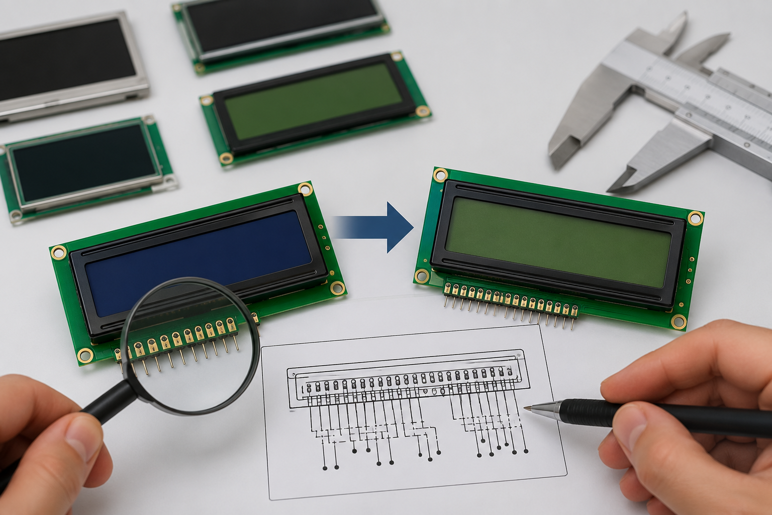
When an LCD module is discontinued, a display with the same screen size and connector may look like a direct replacement. It may still have a different pinout, voltage, controller, timing, backlight, touch panel, or active-area position.
Do not approve a replacement because it powers on once. Check the module against the original design, test it in the complete product, and record every difference before it enters production.

Know What “Compatible” Means
These terms describe different levels of compatibility:
- Pin-compatible: The pin positions, functions, directions, and voltage limits match.
- Mechanically compatible: The outline, thickness, mounting points, active area, connector position, and cable fit the product.
- Firmware-compatible: The existing commands, initialization code, timing, image addressing, and touch driver work without changes.
- Drop-in replacement: No PCB, cable, enclosure, power-circuit, firmware, or production-process change is required.
A module can be pin-compatible but need different initialization commands. That module is not a true drop-in replacement, even if it plugs into the same connector.
Collect the Original Information
Start with the complete part number, including every suffix and revision code. A suffix can identify the controller, backlight, viewing direction, temperature range, touch option, polarizer, or FPC version.
Collect:
- The original LCD datasheet
- The host PCB schematic
- The connector and FPC drawings
- The mechanical drawing
- The firmware initialization code
- The bill of materials
- Old purchase records
- Product-change notices
- Production inspection limits
- An approved working sample
Photograph the front, rear label, FPC markings, connector, touch cable, and any PCB attached to the display. The rear label may show the sales model, while the FPC carries a panel or factory code.
If the original datasheet is missing, inspect the schematic and firmware. Signals such as SCLK, MOSI, WR, RD, HSYNC, VSYNC, DE, PCLK, and RGB data lines help identify how the display is driven.
When reading a candidate datasheet, check power, pinout, interface, timing, initialization, mechanics, and optical data. The article on how to read a TFT LCD module datasheet shows where these details are normally found.
Identify the Display Type
Character LCD
Character LCDs show fixed rows and columns, such as 16 × 2 or 20 × 4. Two modules with the same character format can still use different pin orders, interfaces, fonts, contrast circuits, or backlights.
Compare:
- Pin order
- Four-bit or eight-bit mode
- 6800 or 8080 bus operation
- Supply and contrast voltage
- Enable timing
- Busy-flag behavior
- Character font table
- Backlight polarity and current
Use the character LCD collection to find modules with the required row and column format, then check the exact datasheet before treating any model as an equivalent.
Graphic and COG LCD
A monochrome graphic LCD uses a controller to address pixels. Common controller families include ST7565, ST7567, ST7920, KS0108, UC1701, and RA6963.
Compare:
- Resolution
- Controller model
- Command set
- Page and column addressing
- Display bias and contrast settings
- Required external capacitors
- SPI, I²C, 6800, or 8080 interface
A 128 × 64 display using one controller is not automatically firmware-compatible with another 128 × 64 display using a different controller.
The graphic LCD range and COG LCD range contain modules with different controllers, FPC layouts, glass sizes, and interfaces. Compare the individual product drawings rather than the visible format alone.
Controller-Based TFT
Many small TFT modules use a display controller such as ILI9341, ILI9488, ST7789, or HX8357. The host sends commands and image data through SPI or a parallel MCU bus.
Compare:
- Controller model
- Interface mode
- Initialization commands
- Pixel format
- Image direction
- RGB or BGR color order
- Row and column addressing
- Sleep and wake behavior
The page for this 2.8-inch 240 × 320 TFT module lists the display controller, touch controller, interfaces, resolution, and viewing direction separately. The same fields should be checked for every replacement candidate.
Raw RGB TFT
A raw RGB panel receives a continuous stream of pixel data. It normally uses a pixel clock, data-enable signal, horizontal and vertical synchronization, and separate red, green, and blue data lines.
Two panels with the same resolution can require different pixel clocks, blanking periods, sync widths, signal polarities, or sampling edges.
MIPI DSI
MIPI DSI is a high-speed serial link between a host processor and a display module.[1]
Compare:
- Number of data lanes
- D-PHY timing and voltage requirements
- Video mode or command mode
- Continuous or non-continuous clock
- Pixel format
- Lane order and polarity
- Reset and initialization sequence
MIPI DCS provides standard display-control commands, but a module may also need manufacturer-specific commands and register values.[2]
A passive cable cannot make a processor without a MIPI DSI host drive a MIPI display. An active bridge, a new PCB, and new firmware may be needed.
LVDS
For LVDS, compare:
- Single-channel or dual-channel operation
- Six-bit or eight-bit color
- JEIDA or VESA data mapping
- Clock-frequency range
- Differential-pair order and polarity
- Panel-enable and backlight-control pins
- Power-up and power-down sequence
The complete signal path matters. PCB traces, vias, connectors, and cables can all affect a high-speed differential signal.
The product page for this 7-inch 1280 × 800 LVDS display separates interface, supply, backlight, active-area, timing, and mechanical data. Use the same approach when comparing another LVDS panel.
eDP
eDP is the embedded version of DisplayPort used for internal display connections. VESA publishes the eDP standard and its supported link features.[3]
Compare:
- Lane count
- Link rate
- AUX-channel support
- Link training
- DPCD capabilities
- EDID or DisplayID data
- Panel power sequence
- Backlight control
SPI, RGB, LVDS, MIPI DSI, and eDP are different interfaces. The guide to choosing a display interface explains their main hardware and firmware differences.
Compare Every Pin
Create one row for every connector pin. Do not compare only pin count and pitch.
| Pin | Original Module | Candidate Module | Result | Action |
|---|---|---|---|---|
| 1 | GND | GND | Possible match | Confirm the ground function |
| 2 | VDD, 3.0-3.6 V | VDD, 2.7-3.3 V | Needs review | Measure the real supply voltage |
| 3 | RESET#, input | RESET, input | Unknown | Check the active level |
| 4 | CS# | D/C | Mismatch | Reject or redesign |
| 5 | SCLK | SCLK | Possible match | Check voltage and timing |
For each pin, record:
- Its function
- Whether it is an input, output, or bidirectional pin
- Its voltage range
- Whether it is active high or active low
- Any internal pull-up or pull-down
- Its required state during startup
- Its current limit
- Whether it may be left open
Active-Low Pins
Names such as RESET#, /RESET, nRESET, and CS# usually mean that the function is active when the signal is low. Confirm this in the timing diagram.
If the reset level is wrong, the display may stay in reset or start in an unknown state.
Mode Pins
Pins such as IM0, IM1, IM2, BS0, BS1, and PSB often select the interface mode.
Check whether each mode pin is fixed by the module, set by a resistor, driven by the host PCB, or required to stay high or low.
NC Pins
NC can mean internally unconnected, reserved, used for factory testing, or required to remain open. Do not connect an NC pin unless the candidate datasheet allows it.
Ground Pins
Logic ground, analog ground, touch ground, backlight return, and frame ground may not have the same purpose. Ground pins beside high-speed signals also provide return paths and should not be removed without checking the design.
Check Power and Backlight
Supply Rails
A module described as a “3.3 V display” may still need separate logic, I/O, analog, touch, and backlight supplies.
| Rail | Original | Candidate | Result |
|---|---|---|---|
| Logic VDD | 3.0-3.6 V | 2.7-3.3 V | Check the upper limit |
| I/O voltage | 3.3 V | 1.8 V | Level shifting is required |
| Backlight | 9.0-10.5 V | 15.0-19.0 V | The existing driver is unsuitable |
| Touch supply | 3.3 V | 2.8-3.3 V | Check the real rail tolerance |
Use the recommended operating range, not the absolute maximum rating. The absolute maximum is a damage limit.
If a candidate has a recommended maximum of 3.3 V, measure the real rail during startup. A nominal 3.3 V supply can briefly rise above 3.3 V.
Logic Levels
Suppose the candidate requires:
- Input low below 0.3 × VDD
- Input high above 0.7 × VDD
At VDD = 3.3 V:
- Input low must remain below 0.99 V.
- Input high must reach at least 2.31 V.
A 1.8 V processor output cannot reliably meet a 2.31 V input-high requirement. A 3.3 V processor may damage a 1.8 V input unless that pin is listed as 3.3 V tolerant.
If level shifting is needed, choose a translator that supports the signal direction, speed, voltage, and signal type.
Power Sequence
Use the sequence in the candidate datasheet. A common sequence is:
- Apply the logic supply.
- Wait for the rail to become stable.
- Keep reset active.
- Release reset after the required delay.
- Send initialization commands.
- Enable the display.
- Turn on the backlight.
Do not copy delays from another module. A different controller or panel revision may need a different reset or sleep-out delay.
Also check whether the host may drive signals while the display is unpowered. Current can enter through an input pin and partly power the module.
Current and Power
Record logic current, touch current, sleep current, backlight current, and startup current separately.
For example:
18 V × 20 mA = 0.36 W
18 V × 60 mA = 1.08 W
The second backlight uses three times as much power. The regulator, inductor, switching transistor, connector, and FPC traces must support the higher load.
For battery-powered products, see how to reduce display module power consumption.
LED Strings
A backlight may use one LED, several LEDs in series, or several parallel strings.
A simple estimate is:
3 LEDs × 3.0 V ≈ 9.0 V
6 LEDs × 3.0 V ≈ 18.0 V
These values are examples only. LED voltage changes with current, temperature, and production variation. Use the minimum and maximum values in the datasheet.
Check the backlight driver’s output-voltage range, regulated current, startup limit, protection functions, PWM range, and thermal limit. Do not connect an unknown LED backlight directly to a fixed voltage unless the module includes its own current control.
Check Interface Timing
SPI
For SPI, compare:
- Three-wire or four-wire mode
- Clock polarity and phase
- Maximum clock speed
- Bit order
- Chip-select timing
- Command and data selection
- Readback support
One module may use a separate D/C pin, while another sends a command/data bit inside a nine-bit SPI word. These two methods need different firmware.
Test at the production clock speed. A display that works at 1 MHz may fail at 20 MHz or 40 MHz.
Parallel Bus
For an MCU parallel bus, compare:
- Eight-bit or sixteen-bit width
- 8080 or 6800 operation
- Read and write strobes
- Data setup time
- Data hold time
- Minimum pulse width
- Bus direction
A display may work with slow test code but fail when the final firmware uses shorter write pulses.
RGB Timing
The approximate RGB pixel clock is:
Pixel clock = Horizontal total × Vertical total × Frame rate
The horizontal total includes active pixels, front porch, back porch, and sync width. The vertical total includes active lines, front porch, back porch, and sync width.
For example:
- Horizontal total: 840 clocks
- Vertical total: 525 lines
- Frame rate: 60 Hz
840 × 525 × 60 = 26,460,000 Hz
The estimated pixel clock is 26.46 MHz. The final settings must also stay inside the panel’s allowed porch, sync-width, frame-rate, and pixel-clock ranges.
A wrong clock edge or sync polarity can cause a blank, rolling, shifted, or cropped image.
Check Controller and Firmware
Initialization
Compare:
- Hardware and software reset
- Sleep-out command
- Display-on command
- Required delays
- Pixel format
- Scan direction
- RGB or BGR order
- Row and column addresses
- Gamma settings
- Frame-rate settings
- Display inversion
Use the module manufacturer’s initialization code when possible. A generic controller example may show an image but still cause wrong colors, flicker, high current, image retention, or unreliable startup.
Address Offsets
The controller memory can be larger than the visible panel. The image may therefore start at a non-zero row or column address.
A wrong offset can shift, crop, wrap, or partly hide the image.
Color Order
Show solid red, green, and blue screens. If red and blue are exchanged, the RGB or BGR setting is wrong.
Check Mechanical Fit
Outline and Thickness
Compare drawings, not photographs.
Check:
- Overall width and height
- Maximum thickness
- Corner shape
- Frame and PCB position
- Maximum component height
- Keep-out areas
Use maximum dimensions. A panel with a typical thickness of 4.8 mm and a maximum thickness of 5.2 mm does not fit safely in a 5.0 mm space.
Active Area
Compare the distance from each module edge to the active pixel area. Two screens with the same diagonal size may place the visible image differently.
A shifted active area can hide text, crop icons, or leave uneven borders behind the enclosure window.
Mounting
Compare mounting holes, slots, bezel tabs, adhesive areas, screw clearance, and gasket pressure. A small hole-position difference can place stress on the glass.
FPC and Connector
Check:
- Pin count and pitch
- Contact side
- Cable length
- Exit direction
- Stiffener thickness
- Insertion depth
- Minimum bend radius
A 40-pin, 0.5 mm-pitch FPC is not compatible if its contacts face the wrong direction. The connector may close without making contact.
Check the cable after the enclosure is closed. A cable that reaches on an open bench may be under tension inside the finished product.
Check Image and Touch
Optical Performance
Compare:
- Native resolution
- Brightness
- Contrast
- Viewing angle
- Preferred viewing direction
- Response time
- Surface treatment
- Polarizer type
- Brightness uniformity
IEC 61747-30-1 gives standard measurement methods for transmissive LCD modules, which helps make brightness, contrast, and viewing results more consistent.[4]
IPS usually gives wider viewing angles than TN, but an IPS replacement may also have different thickness, timing, backlight demand, and color appearance. The IPS display collection can help locate candidates, but every electrical and mechanical detail still needs checking.
Test the display through the real cover lens. A panel that looks clear on a bench may show strong reflections or lower contrast after assembly.
For products that show moving content, test motion directly. IEC 61747-30-3 covers motion-performance measurement for transmissive active-matrix LCDs.[5]
Resistive Touch
For a four-wire resistive panel, compare:
- X+, X-, Y+, and Y- pin order
- Panel resistance
- Active area
- Tail position and length
- Operating pressure
A different panel resistance can change drive current, signal-settling time, noise, ADC loading, and calibration.
Capacitive Touch
Compare:
- Touch-controller model
- I²C, SPI, or USB interface
- I²C address
- Interrupt and reset polarity
- Supply voltage
- Number of touch points
- Coordinate range
- Driver support
MIPI Touch defines a set of specifications for display-touch integration, but many modules still use controller-specific commands and drivers.[6]
Test the center, corners, and edges. Check for reversed axes, exchanged X and Y values, offsets, and different maximum coordinates.
Check Temperature and Lifetime
Temperature
Use the exact operating and storage limits in the datasheet. Labels such as “commercial” and “industrial” do not always mean the same temperature range.
At low temperature, the image can respond more slowly. At high temperature, contrast, adhesives, backlight life, touch accuracy, and controller stability can change.
Test:
- Cold startup
- Hot startup
- Image response
- Contrast
- Touch accuracy
- Current consumption
- Backlight brightness
- Sleep and wake behavior
IEC 61747-1-1 gives general rules for electrical, optical, climatic, mechanical, and endurance testing of LCD devices.[7]
Lifetime
Backlight life is often the time until brightness falls to a stated percentage of its starting value. Confirm the percentage, LED current, temperature, and duty cycle used for the rating.
Also check:
- Image retention
- Polarizer and adhesive life
- Touch durability
- Connector insertion cycles
- FPC bend limits
An FPC made for one-time installation should not be used where the cable bends during normal operation.
Check the Supplier
A technically suitable display is still a poor replacement if its revision or supply cannot be controlled.
Ask for:
- Current lifecycle status
- Expected support period
- Minimum order quantity
- Lead time
- Product-change notification
- Revision-control policy
- Lot traceability
- Warranty and failure analysis
- Sample and pilot-batch support
The guide to selecting an LCD module supplier lists additional questions for long-term production.
Broker Stock
Broker or marketplace stock may include old inventory, mixed revisions, relabeled parts, reworked modules, or displays stored under unknown conditions.
Inspect date codes, labels, FPC markings, connector wear, polarizer damage, moisture, and corrosion. Such stock may be suitable for controlled repair work but is risky for long-term production.
Custom Replacement
If no standard module matches the connector, FPC, active area, backlight, or enclosure, a semi-custom display may cost less than redesigning the whole product.
Possible changes include:
- FPC shape and pinout
- Connector position
- Backlight brightness
- Cover glass
- Touch panel
- Mounting features
- Optical bonding
See how to design a custom LCD module when no standard part fits the existing design.
Test the Candidate
Before Power
- Verify the pin table.
- Check the FPC contact direction.
- Measure resistance from each supply rail to ground.
- Confirm backlight polarity.
- Set safe current limits.
First Power-Up
Monitor logic current, backlight current, supply voltage, startup time, and module temperature.
Stop if:
- Current rises unexpectedly.
- The supply enters current limit.
- A component or connector becomes hot.
- A supply rail collapses.
- The display flashes or resets repeatedly.
Image Test
Show:
- White, black, red, green, and blue screens
- Gray levels and color gradients
- Fine horizontal and vertical lines
- Small text
- Moving images
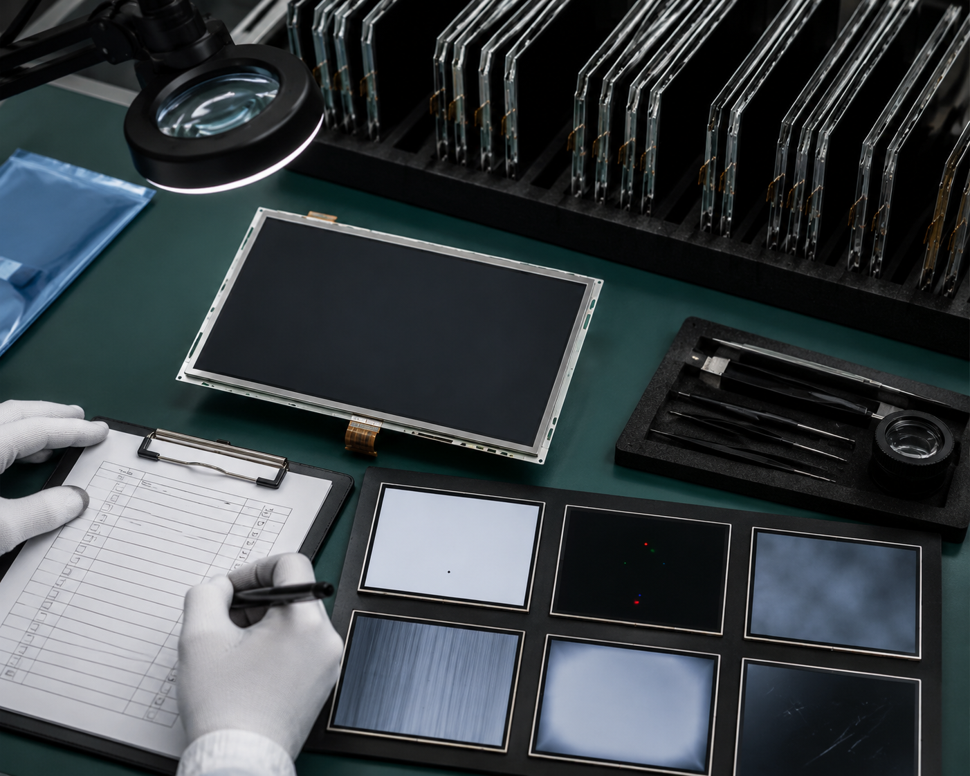
These patterns reveal dead pixels, color-order errors, image shift, flicker, poor gamma, uneven backlighting, and address errors.
IEC 61747-20-3 defines visual-inspection methods and defect terms for active-matrix color LCD modules.[8] Set the allowed defect count and size in the purchase specification agreed with the supplier.
Power and Signal Test
Test cold starts, warm restarts, fast power cycling, slow voltage rise, brownout recovery, sleep, wake, and backlight dimming.
Measure at the display connector:
- Supply ramp and overshoot
- Reset pulse width
- Clock frequency and polarity
- Signal rise and fall time
- Overshoot, undershoot, and ringing
- Power-down sequence
Measuring only at the processor pin may hide problems caused by a cable, connector, resistor, or poor ground path.
Temperature and Long Run
Test the complete product at its required minimum, room, and maximum temperatures. Let the display, PCB, backlight, and enclosure reach the target temperature before recording results.
Run static images, moving content, maximum and minimum brightness, sleep cycles, and repeated updates. Watch for image retention, color shift, flicker, overheating, touch drift, backlight loss, and communication errors.
Pilot Batch
Build a small batch with normal operators, connectors, fixtures, adhesives, screws, gaskets, and production firmware.
One engineering sample cannot show lot variation, assembly stress, cable damage, connector yield, or pressure from the final enclosure.
Classify the Result
| Result | Meaning |
|---|---|
| Drop-in replacement | No PCB, cable, enclosure, power, or firmware change is required. |
| Pin-compatible with firmware change | The pins and mechanics match, but initialization, timing, or image settings must change. |
| Adapter-based replacement | A cable, interposer PCB, level translator, or power change is required. |
| Redesign candidate | Major hardware, firmware, or enclosure changes are required. |
Do not describe an adapter-based or firmware-modified solution as a drop-in replacement.
Control the Change
After approval, update:
- The bill of materials
- The approved supplier list
- The firmware version
- Mechanical drawings
- Inspection limits
- Production test instructions
- Repair documents
- Product configuration records
Record the exact display model, revision, controller, supplier, required firmware, test results, and approval date.
Keep an approved reference sample. If new firmware is required, prevent production from using the new display with the old firmware.
Final Checklist
- The complete original and candidate part numbers are known.
- Every pin has been compared.
- Supply and logic voltages are safe.
- Power sequencing is correct.
- The backlight driver supports the LED load.
- The interface and timing match.
- The controller and initialization code have been tested.
- The outline, active area, mounting, and FPC fit.
- Brightness, viewing angle, response, and surface are acceptable.
- Touch works across the full area.
- Temperature and lifetime requirements are met.
- The supplier controls revisions and traceability.
- The pilot batch has passed.
- Production records have been updated.
Conclusion
Screen size, resolution, connector pitch, pin count, and nominal voltage are useful search filters, but they do not prove compatibility.
A pin-compatible module must match the original pin functions and electrical limits. A true drop-in replacement must also work with the existing mechanics, power circuit, interface timing, firmware, backlight, touch system, operating conditions, and production process.
Compare the datasheets, test the complete product, and record every approved change. This is the safest way to replace a discontinued LCD without creating a new reliability or production problem.
Laisser un commentaire
Ce site est protégé par hCaptcha, et la Politique de confidentialité et les Conditions de service de hCaptcha s’appliquent.