


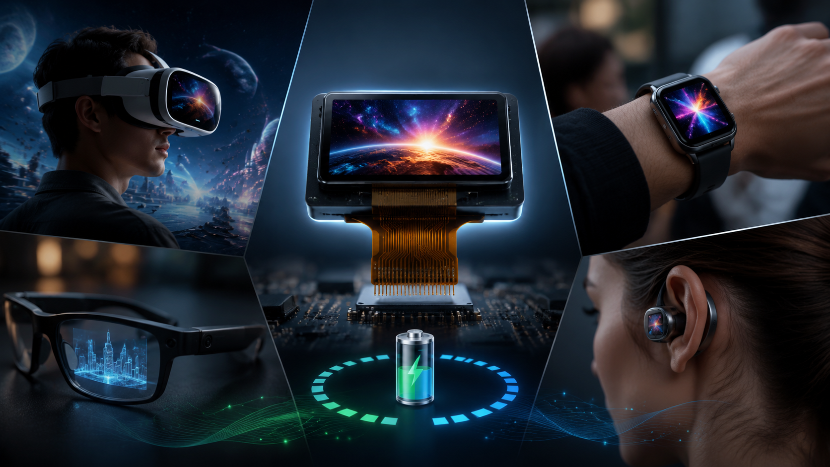
Innovative Micro OLED Module Applications | High Brightness, Low Power, Wearable Devices
Battery-powered embedded systems demand display modules that do not drain power reserves — PMOLED (Passive Matrix Organic Light-Emitting Diode) delivers 2 – 10 mW typical power consumption through self-emissive pixel technology, making it the preferred choice for sub-3-inch embedded applications. I once encountered a blood glucose meter that operated for only 3 days on a full charge; switching to a monochrome PMOLED module extended its runtime to 14 days without any hardware redesign — a nearly 5-fold improvement from the same 800 mAh battery.

Define Embedded Requirements
Equipment Scenarios
Approximately 65% of PMOLED embedded display shipments concentrate in four core application categories — industrial instruments (multimeters, oscilloscopes), medical devices (blood glucose meters, pulse oximeters), home appliances (HVAC panels, washing machines), and automotive electronics (dashboard auxiliary indicators).
All four share the same baseline hardware requirements: ultra-low power draw, wide operating temperature ranges, and high sunlight readability. However, priorities shift dramatically between these categories:
- Handheld Medical Devices: Demand an extended temperature range (−20 °C to +60 °C), a long operational life (LT70 ≥ 30,000 hours), and high contrast for absolute legibility in outdoor environments.
- Industrial Instruments: Prioritize mechanical shock resistance, vibration tolerance, and wide viewing angles (±80°).
- Consumer Appliances: Focus primarily on cost optimization, where a 15,000-hour operational lifespan is often acceptable.
A sensor manufacturer once told me about their experience with a standard 0.96-inch PMOLED module that developed localized dark spots after two years of operation at −10 °C in a northern factory environment. Root cause analysis revealed the module's rated operational temperature floor was only 0 °C, while the −20 °C limit specified on the datasheet cover page was actually the storage temperature. The actual operating environment had crossed the operational boundary — a clear case of specification mismatch during component selection.
Therefore, the first step in display selection is never evaluating cosmetic brightness or resolution — it is confirming the target device's true Operational Temperature Range and expected service life, as these parameters determine whether you need an industrial-grade module (−40 °C to +85 °C) or a consumer-grade module (−20 °C to +60 °C).
Display Content & Resolution
Character modules (such as 16×2 or 20×4 character dot matrices) and graphic modules (such as 128×64 or 96×16 pixel matrices) represent the two primary PMOLED product forms. Character types serve fixed, static text displays like "Power On" or "Error 3," while graphic types enable dynamic user interfaces, custom status icons, and Chinese dot-matrix fonts.
Pixel matrix density directly determines the display resolution: a 128×64 pixel layout at 0.96 inches yields approximately 200 PPI, which is sufficient for rendering clean 16×16 pixel multi-lingual characters or detailed progress bars. Conversely, a 96×16 matrix only handles English numerals and small status icons, lacking the vertical space required for complex character sets.
Graphic module driver ICs (commonly the SSD1306 or SH1106) provide dual SPI/I2C interfaces and require an allocation of a 1 KB frame buffer within the host controller's SRAM. Engineers must confirm their host MCU has adequate unallocated SRAM before committing to the schematic design.
A common pitfall among junior engineers is assuming that higher resolution is always better. In reality, most embedded system interfaces only need to display numbers, English text, and basic system icons. Choosing an unnecessarily high resolution drives up both pixel drive power consumption and raw module costs. I recommend freezing the exact number of characters and icons required by the UI design first, and then working backward to determine the minimum necessary pixel matrix.
Size & Mechanical Constraints
The PMOLED module market covers mainstream sizes ranging from 0.48 inches up to 3.12 inches:
- 0.48-inch (48×24 pixel outline): Dominates ultra-compact wearable bracelets and smart rings.
- 0.96-inch (27.7×19.2 mm active area): Represents approximately 40% of all embedded shipments — the absolute sweet spot for cost-to-performance ratio.
- 1.3-inch (23.7×23.7 mm active area): Perfectly suits compact industrial meters and instrument clusters.
- 2.42-inch (55.0×29.5 mm active area): The largest practical size for standard handheld terminal devices requiring information-dense layouts.
Never confuse Module Outline Dimensions (PCB size) with Active Area (AA) Dimensions. I have seen countless engineering teams select a display based purely on the active area specifications, only to discover during physical prototyping that the surrounding PCB or structural bezel exceeded the device enclosure's reserved space, forcing an expensive emergency enclosure redesign.
In terms of thickness, a PMOLED bare glass panel is approximately 0.2 mm thick, and the total module thickness (including the interface PCB and protective metal frame) typically ranges between 2.0 mm and 3.5 mm. For slim-profile products like smart keys or wearable cases, this represents a thickness reduction exceeding 30% compared to backlit TFT-LCD modules — a massive mechanical advantage.
Keep in mind that changing display dimensions after mass production tooling begins incurs structural injection mold modification costs ranging from $5,000 to $20,000. Always align future product iteration plans with your mechanical team before finalizing the display footprint.
Focus on Display Characteristics
Low-Power Optimization
PMOLED typical power consumption ranges from a mere 2 mW to 10 mW, which is substantially below the 50 mW to 200 mW required by equivalently sized backlit LCD panels. This massive gap directly translates into extended battery lifecycles for portable hardware. With a standard 800 mAh lithium polymer battery, an LCD display device might deplete the power reserves in just 8 hours, whereas a PMOLED device can easily sustain continuous operation for 33 hours or more under identical duty cycles.
The core mechanism behind these power savings is the self-emissive solid-state architecture: PMOLED pixels draw current only when they are actively illuminated, and non-displayed areas (black pixels) consume zero functional power, with leakage currents dropping below 1 μA. Conversely, LCD panels require continuously powered LED backlights regardless of the displayed content — whether the screen shows pure white or pure black, the backlight power draw remains a constant drain. Therefore, the higher the proportion of dark backgrounds in your UI design (dark mode), the more pronounced the PMOLED power advantage becomes.
When designing low-power battery-operated solutions, do not focus solely on the "typical power consumption" listed on page one of the datasheet. You must explicitly evaluate three specific data states: Typical Operating Power (at a balanced pixel-on ratio of around 30%), Full-White Maximum Power (typically 20 – 50 mW when driving 100% of pixels at 200 cd/m²), and Deep Sleep Mode Power (which should drop down to 0.001 mW).
Monochrome Graphics & Environmental Resilience
With a static contrast ratio exceeding 10,000:1, an unrestricted viewing angle of nearly 180°, and a sub-1 μs response time, monochrome PMOLED delivers these premium optical metrics by default. This makes it an incredibly reliable choice for outdoor high-ambient and high-speed data-refresh embedded applications.
Monochrome PMOLED contrast ratios typically exceed 10,000:1 because the black luminance drops below 0.01 cd/m², which is vastly superior to standard TFT-LCDs that struggle around 1,000:1 due to backlight bleeding. The sub-1 μs response time entirely eliminates the liquid crystal ghosting and motion blur inherent to LCDs, a feature that is critical for real-time data visualization such as portable oscilloscope waveform displays.
Furthermore, low-temperature performance is a native advantage of OLED materials. A PMOLED display will power on and refresh normally at −30 °C without any lag. Liquid crystals, on the other hand, suffer a severe increase in viscosity below −20 °C, leading to sluggish response times, freezing frames, and eventual total display failure. For industrial or medical equipment deployed outdoors in extreme winter climates, monochrome PMOLED is often the only viable choice.
Interface Selection Protocols
SPI (Serial Peripheral Interface) and I2C (Inter-Integrated Circuit) represent the two mainstream protocols for modern small-sized PMOLEDs, while legacy Parallel buses (8080/6800) are reserved for specialized retrofits. The fundamental engineering trade-offs lie in data throughput, required I/O pin counts, and host MCU routing complexity:
- SPI (4-Wire Serial): Delivers high communication rates up to 10 MHz (typically optimized at 4 – 8 MHz in production firmware) while requiring only 4 hardware pins (CS, SCK, MOSI, DC). It interfaces seamlessly with almost all modern MCUs (STM32, ESP32) using standard driver libraries, making it the most recommended interface for embedded projects.
- I2C (2-Wire Serial): Requires only 2 pins (SDA, SCL) but is throttled by data rates capped between 400 kHz and 1 MHz. This interface is ideal for ultra-low-cost designs with severely constrained pin budgets, though slave address planning must be carefully locked down in advance to prevent bus conflicts.
- Parallel Interfaces (8080/6800 architectures): Though supporting high bus speeds, they require 8 to 16 dedicated data pins, significantly increasing PCB routing density. Given that the physical refresh rate of PMOLED is internally capped by its row-scanning mechanism, parallel interfaces offer minimal practical visual advantage over SPI for sub-3-inch screens and are rarely specified in new low-power designs.
During an integration project, an engineering team insisted on using an I2C-configured SSD1306 module, but the schematic already had three other high-frequency sensors sharing that exact same bus. Inadvertent address collisions and bus arbitration delays caused the PMOLED and the system accelerometer to intermittently lock each other out. Standardizing the display onto a dedicated SPI channel eliminated the architectural risk immediately. I highly recommend validating I2C address maps during early schematic review or defaulting to SPI to bypass the risk entirely.
Select a Custom Module Manufacturer
Module Solution Engineering
Customizing a commercial-grade PMOLED module solution requires delivering 6 core parameters to the manufacturer's engineering team: Active Area Dimensions, Pixel Resolution, Interface Protocol, Operating Temperature Grade, Baseline Brightness Requirement, and Connector Type.
Active area dimensions must be specified to a tolerance of ±0.10 mm because frame widths dictate the exact enclosure bezel cutout dimensions. Brightness requirements need explicit definition based on the deployment environment:
- Indoor standard: 100 – 150 cd/m² (Standard material grade)
- Outdoor shaded: 300 – 500 cd/m² (High-efficiency material stack)
- Direct sunlight readable: 700+ cd/m² (Premium premium-emitter grade; premium pricing)
I always advise engineers against blindly pursuing the maximum 700+ cd/m² brightness spec unless it is an absolute requirement. In OLED technology, forcing high brightness accelerates material aging exponentially; halving the brightness target typically extends the display's operational lifespan from 15,000 hours to over 30,000 hours. A rational selection simultaneously protects your project budget and extends field reliability.
The connector type (e.g., 0.5 mm pitch FPC, 1.0 mm pitch pin headers, or ZIF configurations) directly dictates product assembly metrics. One hardware team discovered late in the process that their chosen FPC connector configuration did not match the setup parameters of their SMT pick-and-place line, forcing them to switch to manual hand-soldering for the display cable at an unbudgeted assembly cost penalty. Ensure all connector footprints are completely frozen during the initial Design for Manufacturability (DFM) review stage.
Rigorous Sample Testing Protocol
Upon receiving initial engineering samples from the factory, simply powering on the module to verify that it lights up is completely insufficient. Each display batch must be vetted across a formalized 5-dimensional verification matrix before approving mass production tooling:
- Visual Ingress Inspection: Scan under a microscope for microscopic bright/dark pixel spots, polarizer bubbling, and surface micro-scratches.
- Electrical Parametric Check: Validate typical operating voltages (4.5 V – 5.5 V) and monitor current draw across full-white and deep-sleep states to ensure compliance with the datasheet.
- Interface Protocol Functionality: Run continuous high-frequency register read/write sequences to check for bit errors or signal attenuation.
- Optical Metrology Calibration: Use a luminance colorimeter to verify that absolute brightness and CIE color coordinates align with the agreed-upon specification limits.
- Accelerated Reliability Screening: Subject a sample subset to a 96-hour environmental stress sequence at 85 °C and 85% RH humidity to check for adhesive delamination.
Burn-in testing is the most critical reliability check for PMOLED: display a static, high-contrast image (such as an asymmetrical font grid) at maximum brightness for 4 continuous hours, then switch the screen to a uniform 50% gray field. Check for visible residual ghost images. Minor afterimages that fade away completely within 30 minutes are acceptable; persistent, permanent ghosting indicates poor OLED organic deposition uniformity and justifies an immediate rejection of the batch.
Long-Term Supply Chain Risk Mitigation
The global PMOLED manufacturing market is highly consolidated, with major market share controlled by premier specialized display fabs in Taiwan (such as RiTdisplay and WiseChip) and mainland China (such as Truly and QingYue). Because of this high market concentration, the primary source of long-term supply risk is not component quality, but sudden line obsolescence or corporate restructuring that shifts factory capacity away from legacy low-volume industrial runs.
Following a major PMOLED manufacturer's capacity reallocation, a smart thermostat provider was hit with a sudden End-of-Life (EOL) notice on their primary 1.3-inch display module. The engineering validation, re-tooling, and firmware recertification cycle for an alternative vendor stretched to 6 months, forcing a production line shutdown that resulted in significant lost market revenue. This highlights why long-term component procurement strategies must include vendor equity and production stability analysis.
The gold standard for mitigating this risk is a strict dual-source supply strategy: allocate 80% of volume to your primary vendor and 20% to a verified backup supplier. Both display modules must be completely pin-to-pin mechanically compatible and software-compatible (sharing identical driver ICs or register initialization scripts), allowing immediate assembly hot-swapping without requiring a PCB redesign. Furthermore, given that custom industrial PMOLED lead times average 8 to 16 weeks, you should mandate a 4 to 8-week safety stock buffer at the distributor level, coupled with a formal Letter of Continuity guaranteeing a minimum 5 to 7-year product availability lifecycle.
According to Display Supply Chain Consultants (DSCC) market tracking reports, the global PMOLED sector remains highly robust within specialized verticals, commanding an annual market value of approximately $850 million. Industrial instrumentation and medical hardware account for over 40% of this footprint, scaling at a steady compound annual growth rate (CAGR) of 12% — vastly outperforming standard consumer-grade legacy panels.
Per the Society for Information Display (SID) Technical Seminar Papers: Because a monochrome PMOLED stack naturally operates without the heavy light-attenuating polarizers and color filters required by TFT-LCDs, it retains an impressive 50:1 native contrast ratio under high ambient illumination. When treated with an external vacuum-deposited anti-reflective (AR) coating, it easily complies with the stringent SGS Class 2 outdoor visibility standard under direct 10,000 lux testing conditions.
Per IEEE Electronic Device Reliability Data: The operational lifetime (LT70) for industrial-grade PMOLED modules operating across a balanced 30% pixel-on load can reliably sustain up to 50,000 hours. Conversely, standard backlit TFT-LCD reliability routinely degrades down to approximately 28,000 hours in sub-zero environments due to cold-start voltage shocks on the miniature LED backlight array.
Per WiseChip Semiconductor Industrial Product Lifecycle Guide: While standard off-the-shelf display footprints carry a production lead time of 8 – 16 weeks, customized ODM module configurations (involving custom FPC geometry, tailored glass bezels, and specialized firmware initialization) require an extended engineering verification and certification lifecycle of 16 – 24 weeks. Time-to-market roadmaps must embed this buffer during early product scheduling.
| Parameter | PMOLED Module | TFT-LCD (With LED Backlight) | Engineering Advantage |
|---|---|---|---|
| Typical Power Draw | 2 – 10 mW | 50 – 200 mW | PMOLED (3× to 20× lower power drain) |
| Static Contrast Ratio | > 10,000:1 | ~ 1,000:1 | PMOLED (Absolute blacks, no bleeding) |
| Response Latency | < 1 μs | 10 – 50 ms | PMOLED (Zero motion blur for waveforms) |
| Low-Temp Startups | −30 °C normal execution | Severe response lag below −20 °C | PMOLED (No heater required in cold climates) |
| Physical Thickness | 0.2 mm bare panel / 2.0 – 3.5 mm assembly | 3.0 – 6.0 mm (constrained by backlight) | PMOLED (30%+ thinner structural profile) |
| Viewing Angle Arc | Nearly 180° full unrestricted view | ~ 170° (Prone to off-axis color inversion) | PMOLED (Consistent readability from any angle) |
| Operational Lifespan | 15,000 – 50,000 hours (governed by brightness/load) | 30,000 – 60,000 hours | Technically equivalent under de-rated design |
| Color Capability | Monochrome (Yellow, Blue, White, Green, Amber) | Full 16.7M RGB Color Space | TFT-LCD (Required for rich graphic UI) |
| Unit Cost Base | $1.50 – $8.00 (For 0.48 to 2.42-inch footprints) | $3.00 – $15.00 (Varies widely by interface) | PMOLED (Significantly cheaper for small matrix screens) |
Conclusion
The core engineering decision logic for selecting a PMOLED display module boils down to four decisive system constraints: strict low-power targets (battery-driven), harsh environmental demands (sub-zero or direct outdoor sunlight), severely restricted mechanical thickness, or clean monochrome interface tracking. Checking even one of these boxes makes PMOLED the clear architectural choice. Standard backlit TFT-LCD hardware should only enter your consideration track if your system maps strictly require full-color asset rendering or larger display sizes scaling past 3.5 inches. For the vast majority of medical, industrial, and specialized smart-grid embedded hardware developments, PMOLED represents the most elegant, robust, and cost-effective display architecture available.
En lire plus
The light transmittance of transparent PMOLED displays typically reaches 40% to 60%. Its core lies in the elimination of the backlight layer, utilizing the self-emissive characteristics of organic ...
The global microdisplay market reached $1.92 billion in 2024, with Omdia projecting the near-eye display market to exceed $1.2 billion by 2026. The Sony ECX350F—boasting a 5,000 PPI pixel density...
Laisser un commentaire
Ce site est protégé par hCaptcha, et la Politique de confidentialité et les Conditions de service de hCaptcha s’appliquent.