


Transparent PMOLED Displays | Transmittance Rate, Use Cases & UI Design
The light transmittance of transparent PMOLED displays typically reaches 40% to 60%. Its core lies in the elimination of the backlight layer, utilizing the self-emissive characteristics of organic light-emitting diodes.
In UI design, dark backgrounds and high-contrast icons should be used to ensure light penetrates the non-emissive areas.
Currently, this technology is commonly used in automotive HUDs, smart wearables, and luxury display windows, achieving an augmented reality interactive visual experience by overlaying virtual scenes onto reality.
Transmittance Rate
Transmittance is the fundamental parameter of transparent PMOLED, directly influenced by the resistance value of the ITO (Indium Tin Oxide) anode, the total thickness of the organic layers (usually about 100-200nm), and the transparency of the metal cathode.
The transmittance of standard modules on the market mostly falls between 40% and 55%.
When the PPI (Pixels Per Inch) exceeds 100, the blockage rate of non-transparent metal leads increases, causing the overall transmittance to decay at a rate of approximately 2% for every 10 PPI increase. Balancing conductivity and optical penetration is the key to production.
Optical Loss in Structural Layers
The outermost layer of low-iron tempered glass or Polyimide (PI) substrate typically has a thickness between 0.5mm and 1.1mm. Although glass itself has a theoretical transmittance of 91.5%, a reflection loss of 4% occurs at a single interface due to the refractive index difference between air and glass (approx. 1.0 vs. 1.5). In actual module production, by depositing a 100nm thick Anti-Reflection (AR) coating, single-sided reflection can be reduced to below 0.5%, thereby increasing the net transmittance of the substrate to about 98%.
Closely attached to the substrate is the ITO (Indium Tin Oxide) anode layer, with a thickness usually controlled between 100nm and 150nm. This layer must strike a balance between a sheet resistance of 10 to 20 Ω/sq and optical transparency. Although ITO has strong penetration in the 550nm band, it produces significant absorption peaks near ultraviolet (<380nm) and infrared (>780nm) regions, leading to a broad-spectrum light loss of about 2% to 3%.
- HIL/HTL Injection Layers: With a thickness of only 10nm to 30nm, these often use organic materials like PEDOT:PSS, resulting in extremely low light loss of about 0.5%.
- EML Emissive Layer: As the core, its 100nm thickness contributes stably to transmittance, but the molecular arrangement of the material produces a slight scattering effect.
- ETL/EIL Electron Transport Layer: A thin layer corresponding to the anode; its refractive index must match surrounding materials to reduce brightness loss caused by Total Internal Reflection (TIR).
The metal cathode is the biggest obstacle in the structure and the essential difference between transparent PMOLED and standard PMOLED. Traditional screens use aluminum or silver with a thickness exceeding 100nm as a mirror, with 0% transmittance. The transparent version uses an ultra-thin Magnesium-Silver alloy (Mg:Ag) of 12nm to 15nm, maintaining transmittance typically between 50% and 70%.
If the cathode thickness increases to 25nm, transmittance immediately drops below 30% accompanied by severe reflection; if thinned to 8nm, although transmittance rises to 80%, the poor continuity of the film causes a surge in resistance, leading to obvious luminous non-uniformity across the screen.
As light travels through these nanometer-scale layers, a Micro-cavity Effect is generated. Light of specific wavelengths is enhanced while others are weakened. For example, when a transparent PMOLED displays a pure white background, objects observed through the screen often have a slight pale yellow tint. This is because the metal layer's absorption rate for blue light (450nm) is about 4% higher than for red light (650nm).
- Interface Reflection: Four physical interfaces (air-glass, glass-ITO, organic-metal, metal-air) contribute to a 12% attenuation.
- Metal Absorption: The 15nm Mg:Ag alloy layer directly absorbs or reflects 25% to 35% of incident light.
- Internal Reflection Loss: About 5% of the light is trapped inside the glass substrate as lateral light guides due to total internal reflection angles.
These physical limitations of the hierarchical structure mean that the ultimate transmittance of the thin-film stack is hard to break 75% without accounting for pixel blockage. To offset this physical loss, high-performance modules cover the cathode with an additional CPL (Capping Layer). This layer of high-refractive-index material, about 60nm thick, uses optical interference principles to boost overall transmittance by another 3% to 5% while correcting the color shift caused by the metal layer.
Pixel Layout & Aperture Ratio
For a standard 1.51-inch transparent screen with a resolution of 128 x 64, the physical size of each sub-pixel is approximately 50μm x 150μm. To ensure the stability of current driving, a non-emissive gap of 10μm to 15μm must be reserved around the pixels. This layout directly limits the maximum passing area for light, making static transmittance an inverse function of pixel density (PPI).
When the PPI is set at around 80, the effective emissive area of a single pixel is usually controlled at 35%. The remaining 65% of the space serves as a transparent window, allowing external light to pass through. If the resolution is increased to 200 PPI and the pixel pitch is reduced to about 5μm, the overall transmittance drops sharply from 55% to 38% as the blockage rate of opaque metal traces surges from 8% to 18%.
- Luminescent Zone: Uses a stack of 150nm thick organic films, producing about 15% absorption loss for visible light.
- Metal Trace Zone: Usually uses 300nm thick Aluminum (Al) or Molybdenum (Mo) wires, which are completely opaque.
- Passivation Layer Gaps: Filled with SiO2 or SiNx with transmittance up to 98%.
The impact of this spatial arrangement on visual transparency can be quantified in the following table, showing how different pixel specifications lock optical parameters:
| Pixel Pitch | Drive Trace Width | Aperture Ratio | System T% |
|---|---|---|---|
| 300 μm | 12 μm | 15% | 78% - 82% |
| 200 μm | 10 μm | 30% | 60% - 65% |
| 150 μm | 8 μm | 45% | 45% - 52% |
| 100 μm | 6 μm | 55% | 30% - 35% |
To balance display brightness and background clarity, researchers often adopt asymmetric pixel designs. This scheme narrows the longitudinal lead width (from 12μm to 5μm) and moves the driving circuitry to non-display border areas as much as possible. Although this increases lithography costs by 15%, it can raise the perceived transparency of a 45% aperture module to a visual level of nearly 60%.
Physical blockage by the circuit layer depends not only on area but also on refractive index matching of materials. Filling pixel gaps with a high-transparency polymer (refractive index approx. 1.45) reduces Fresnel reflection caused by air interfaces by 4%. This optical filling technology, combined with ultra-thin metal lines, reduces the edge diffraction fringe width of background objects by 40%, greatly improving the sharpness of the fusion between virtual and real elements.
- Line Width Effect: Drive current must pass through metal lines; if the width is below 3μm, resistance increases, leading to a temperature rise of 5°C-8°C.
- Fill Factor: Increasing the gap area brightens the background but reduces the peak luminance of the display.
- Diffraction Interference: The smaller the pixel aperture, the more obvious the diffraction phenomenon when light passes through, causing background objects to appear blurry.
This micro-level game of physical dimensions dictates that transparent PMOLED cannot blindly pursue high resolution. In safety-critical scenarios like automotive HUDs, pixel pitches above 300μm are prioritized to ensure drivers obtain an environmental perspective rate of over 70% while meeting a contrast demand of over 1000 cd/m².
Ambient Contrast Ratio (ACR)
Because transparent PMOLED removes the Circular Polarizer that absorbs reflected light, its surface reflectivity is usually as high as 15% to 20%. In contrast, standard smartphone screen reflectivity is typically controlled below 4%. In a typical indoor office environment (approx. 500 lux), if the screen brightness is only 300 nits, the contrast ratio will drop to 5:1 due to the noise floor brought by high reflectivity.
Even with 15nm ultra-thin Mg:Ag alloy, specular reflection of ambient light still exists. When background light increases to 10,000 lux (overcast outdoor), the ambient reflected light (L_off) will surge to over 1,500 nits.
To maintain a minimum readable contrast of 3:1 in this environment, the screen emission brightness must be forced up to 3,000 nits. Such high-load driving accelerates the decay of OLED organic materials by 250% and produces a significant pixel temperature rise (approx. 12°C-15°C).
To optimize ACR without sacrificing 45% transmittance, developers introduce LR/AR (Low Reflection/Anti-Reflection) films. These nano-scale interference coatings reduce interface reflectivity from 8% to 1.2% through destructive interference. In the same 500 lux environment, contrast for a screen of equal brightness can leap from 5:1 to 28:1, greatly improving text edge sharpness.
- Diffuse Reflection Control: Micro-matte treatment on the back of the glass substrate converts specular reflection into diffuse reflection, reducing glare by 30%.
- Dark State Optimization: When displaying black (completely transparent), the brightness of background objects directly serves as the "black level" of the screen.
- Dynamic Brightness Adjustment: Combined with a Light Dependent Resistor (LDR), the PWM duty cycle is linearly adjusted between 1% and 99% to adapt to ambient changes.
The refractive path of light in transparent media also affects perceived ACR. Due to the air gap in PMOLED structures, light undergoes two total reflection losses when entering and leaving the module. Using Optical Clear Adhesive (OCA) with a refractive index (n) of 1.49 for full lamination eliminates interface reflection loss and boosts effective contrast by 15%.
- Background Brightness: The higher the reflectivity of background objects (e.g., a white wall), the lower the equivalent contrast.
- Light Angle: Reflection from metal lines is strongest at an incident angle of 45°, where contrast attenuation can reach 60% of the nominal value.
- Color Saturation: High ACR ensures that the color gamut coverage (NTSC) for R/G/B remains above 72%.
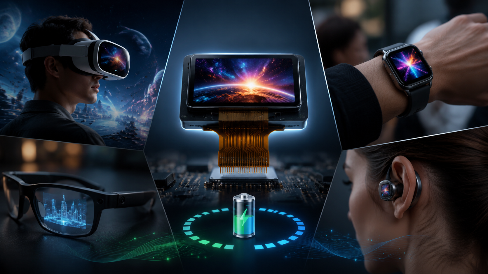
Use Cases
With a transmittance of 40% to 60%, an extremely thin structure of only 1.1mm to 1.5mm, and the ability to work stably in environments from -40°C to 85°C, transparent PMOLED has become the preferred choice for non-backlit display solutions.
Its response time is typically less than 10μs, and the contrast ratio in dark light can reach over 10,000:1.
Currently, the technology mainly covers the small-size market from 1.5 to 2.4 inches, with single-screen power consumption maintained between 50mW and 150mW when displaying common icons, suitable for CR2032 or small lithium battery drives.
Smart Wearables
In smart wearables, the physical thickness of transparent PMOLED is usually compressed to between 0.3mm and 0.5mm, allowing it to fit directly on the inner side of a sapphire watch crystal. This layered structure uses OCR (Optical Clear Resin) full lamination to reduce internal air layers, bringing reflectivity down to below 0.5% and ensuring users can clearly see the mechanical gears below on a 1.5-inch dial.
- A 128 x 64 resolution provides a pixel density of approx. 100-110 PPI in a 30mm diameter circular area.
- Operating current for static display is only 2mA to 5mA, supporting 5-7 days of battery life on a 200mAh battery.
- Peak brightness is set at 800 cd/m² to 1200 cd/m², enough for clarity under 50,000 lux sunlight.
The pixel response speed of 10μs eliminates ghosting during fast scrolling of notifications, nearly a thousand times faster than traditional TFT-LCD. This technology allows designers to display heart rate (BPM) or blood oxygen (SpO2) in the center of the dial without obstructing the physical watch hands.
Smart Home
In smart home hardware, 1.1mm to 1.3mm thick modules are seamlessly embedded into tempered glass panels or acrylic knobs. This integration utilizes the high conductivity of ITO coatings to maintain 10,000:1 contrast while keeping transmittance above 50%, giving digital information a floating feel against dark appliance backgrounds.
| Appliance Type | Integration Position | Typical Data | Power Performance |
|---|---|---|---|
| High-end Oven | Outer layer of triple-pane glass | Time left, Real-time Temp | 75mW / 30% pixels on |
| Smart Humidifier | Top of transparent water tank | Water level, Filter life % | 45mW / 15% pixels on |
| Smart Door Lock | Under mirrored tempered glass | PIN entry, Battery alert | 120mW Peak pulse |
Automotive HUD & Two-Wheelers
In the two-wheeler and compact automotive HUD market, peak brightness is often pushed above 1500 cd/m². This high luminance, combined with a 1.2mm ultra-thin substrate, ensures an environmental contrast of 2,000:1 under 80,000 lux direct sunlight.
This transparent screen offers significant advantages in motorcycle helmet visor integration. Transmitting signals to the visor edge via FPC flexible pins, single-pixel power is only 0.05mW. This low-heat characteristic prevents visor fogging caused by display heat, maintaining visual clarity in 95% relative humidity.
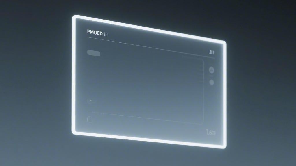
UI Design
On 1.51-inch, 126x64 resolution hardware, UI core data focuses on an extremely low pixel occupancy of 15%-20%.
With a physical penetration of over 70%, the UI layout completely removes traditional background layers, defining black pixels (#000000) as fully transparent. Every icon and character seen by the user is a luminescent dot matrix overlaid directly on background objects.
Pixel Color & Brightness
Lacking a backlight, color rendering depends on individual pixel efficiency. Cyan (#00FFFF) and Emerald Green (#00FF00) have the highest electro-optical conversion rates. At 3.3V, green pixel brightness decay is only a quarter of that of blue pixels.
- Cyan (#00FFFF): High-frequency use, 450 cd/m² at 25mA.
- Pure White (#FFFFFF): Highest visual acuity, requires all sub-pixels at full load.
- Amber (#FFBF00): Strong fog penetration, used for 3000 lux outdoor environments.
- Pure Red (#FF0000): Lower luminous intensity (40% less than green) at equal voltage.
To suppress the Halo Effect (refraction within the glass), designers limit the lit area of pixels. At least 3 physical "off" pixels (0.25mm) are kept between adjacent emissive components. Using a 1px black stroke technique can increase edge sharpness by 40%.
Minimalist Typography
In the 128x64 array, fonts must be sans-serif like Roboto or Inter to prevent visual bleeding. Stroke widths are forced to 1 pixel (1px) to ensure dot matrices do not merge on transparent media.
- 16px Large: For 1-meter viewing distance (Speed, Battery).
- 10px Medium: For 50cm viewing distance (Menus, Time).
- 6px Minimum: Extreme limit for simple 5x5 icons or short abbreviations.
Letter spacing is increased by over 15% compared to standard screens to fight retinal interference. This ensures a 2-pixel "extinguished zone" between characters, preventing halo fusion.
Icon Outlined Design
Icon design shifts from "plane fill" to "geometric outline." To keep transmittance high, all icons must use an Outlined style with 1px width. A 16x16 icon in this style lights up less than 0.8% of the total area, ensuring the background remains 95% intact.
- Standard Size: 16x16 or 20x20 pixels.
- Geometric Constraints: Corner radii are kept within 2 pixels to avoid aliasing.
- Visual Hierarchy: Warning icons use 2px local bolding; status icons maintain 1px thin lines.
- Monochrome Palette: High-saturation single colors to maintain contrast against real-world backgrounds.
En lire plus
Resistive Touch Panels (RTP) generate signals through physical contact between two conductive layers driven by pressure, featuring IP54-rated dust and water resistance. During use, coordinates must...
Battery-powered embedded systems demand display modules that do not drain power reserves — PMOLED (Passive Matrix Organic Light-Emitting Diode) delivers 2 – 10 mW typical power consumption through ...
Laisser un commentaire
Ce site est protégé par hCaptcha, et la Politique de confidentialité et les Conditions de service de hCaptcha s’appliquent.