









Custom Micro OLED Display Manufacturer Selection Guide | AR Glasses, EVF, Near-Eye Integration
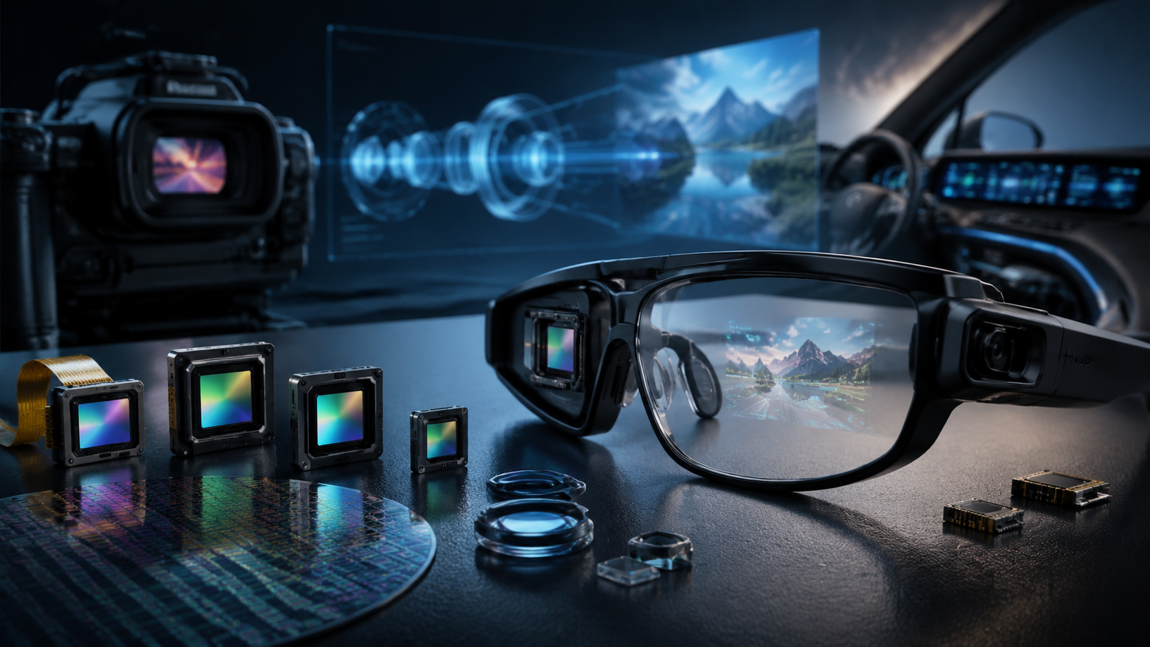
Global demand for custom Micro OLED displays is growing at 23% annually. Small-batch runs of 50–500 units typically require 8–14 week lead times—a timeframe that offers more flexibility than standard consumer panels but depends heavily on the manufacturer's engineering depth. Unlike off-the-shelf OLEDs, custom Micro OLEDs for AR glasses, Electronic Viewfinders (EVF), and near-eye medical devices require direct engagement with manufacturers or specialized distributors that provide firmware customization and precise optical alignment services.

Define Your Need
Use Case and Luminance Mapping
Luminance mismatch is the single most common cause of AR project failure. While 500–1,000 nits suffice for indoor use, outdoor sunlight-readable AR demands 3,000–10,000 nits, and medical surgical navigation requires at least 3,000 nits of sustained brightness to remain legible under intense theater lighting. Insufficient peak brightness results in a washed-out image with zero practical utility in high-ambient-light environments.
The Sony ECX350F achieves a peak brightness of 10,000 nits at a 100% duty cycle, but continuous high-power operation drives surface temperatures above 45°C. In real-world deployments, a Luminance Derating rule is essential: outdoor and medical applications should plan for a 30% brightness headroom. Micro OLED efficiency typically degrades at a rate of approximately -0.5% per degree Celsius above ambient; at an operating temperature of 85°C, a panel may only output 60% of its rated brightness at 25°C. Always calculate effective brightness based on the thermal working point, not just the datasheet peak.
| Application | Luminance Requirement (Eye-Entry) | Headroom Reserve | Color Gamut |
|---|---|---|---|
| Indoor AR | 500–1,000 nits | None | 100% sRGB |
| Outdoor AR | 3,000–10,000 nits | 30% Reserve | 100% sRGB |
| Medical/Surgical | 3,000+ nits | 20% Reserve | 100% DCI-P3 |
| Industrial EVF | 1,000–3,000 nits | 15% Reserve | 100% sRGB |
Per Omdia's 2024 Microdisplay Market Report, the near-eye display market is projected to reach $1.2 billion by 2026—a 200% year-over-year surge—with Micro OLED penetration in AR/VR growing from 18% in 2024 to 47% by 2028.
Optics Match and Resolution Trade-offs
The Sony ECX350F’s 5.1µm pixel pitch dictates the physical ceiling for angular resolution. In Birdbath or Freeform optics, there is a fundamental trade-off between Field of View (FOV) and image sharpness. To maintain Retina level clarity (typically 60 PPD), increasing the FOV requires a proportional increase in pixel density—a hard physics constraint that software interpolation cannot solve.
In a recent 56-degree FOV AR project, selecting the 5,000 PPI Sony ECX350F resulted in an angular resolution of 21 arc-seconds—just below the 24 arc-second human resolution threshold, causing slight text blur. The solution was to either shrink the FOV to 52 degrees to recover PPD or switch to a lower-PPI panel with optimized optical magnification. The takeaway: PPI sets the theoretical ceiling, but the optical focal length determines the perceived PPD—both must be aligned during the hardware design phase.
- Wide-Angle Strategy (FOV > 55°): Target 3,000–3,400 PPI (e.g., eLsen ES027Q, 0.49", 2560x2560) to maintain an angular resolution of ~25 arc-seconds.
- High-Definition Strategy (FOV < 50°): Utilize 4,500–5,000 PPI (e.g., Sony ECX350F, 0.44", 1920x1080) for ultra-sharp rendering at ~20 arc-seconds.
- Critical Missions: Prioritize eMagin military-spec panels with over 100,000:1 contrast and MTBF exceeding 10,000 hours under MIL-STD-810H conditions.
Interface Selection
The interface type (MIPI vs. eDP) significantly impacts system power budget and mechanical volume. MIPI 4-lane at 1.5Gbps is necessary to drive a 1920x1080 resolution at 120Hz. While MIPI layout is more complex due to signal integrity demands (V-diamond termination loss must stay below -6 dB), it consumes 12% to 18% less power than eDP, making it the preferred choice for battery-operated wearables.
- MIPI: Low power, industry standard for AR/VR, but requires high-density PCB design.
- eDP: Supports longer transmission distances (ideal for helmets or EVFs), but consumes ~15% more power and requires careful EMC pre-assessment due to potential interference with optical sensors.
- CPU RGB: Only recommended for low-resolution debugging or legacy products; not suitable for modern high-PPI Micro OLED projects.
Check Factory Ability
Panel Specifications and Measurement Accuracy
Sony remains the leader in mass-produced pixel density with the 5,000 PPI ECX350F, while eMagin specializes in high-reliability 0.39-inch to 1-inch modules for defense. eLsen offers the broadest size range (0.26" to 1") for specialized industrial needs. However, contrast ratios are often misleading: a 100,000:1 datasheet rating typically reflects lab conditions in total darkness. In practice, ambient stray light within the optical engine reduces effective contrast to below 50,000:1.
Always verify measurement conditions: Was the data taken at a steady-state 25°C or at peak operating temperature? Sony and eMagin offer luminance measurement reports; verify that deviations between the datasheet and actual samples stay within the plus/minus 15% tolerance range.
Custom Driver IC Matching
Locking in the driver IC during the EVT (Engineering Validation Test) stage is critical. Changing the driver (e.g., from a Realtek RTD2660 to an Allwinner MR527) during later stages can cause a three-month delay due to the required redesign of the optical engine and mainboard. The Allwinner MR527 is frequently preferred for high-refresh designs as it maintains a cooler surface temperature (approximately 42°C at 90Hz) compared to the RTD2660 (approximately 55°C at 120Hz), which is prone to thermal throttling.
- Frame Time Jitter: Must stay below 0.5ms; human sensitivity can detect jello effects when jitter exceeds 0.3ms at high refresh rates.
- Firmware Support: Ensure the driver allows for future Gamma and color temperature calibration after mass production, otherwise the panel is locked into fixed parameters.
- Bandwidth Overhead: 120Hz at FHD resolution requires 4-lane MIPI at 1.5Gbps; ensure the driver IC can sustain this without signal degradation.
Sample and Stress Testing
EVT samples must undergo a 4-dimensional test suite: Optical (Uniformity >85%), Drive (Power/Standby), Environmental (Thermal shock), and Lifetime (1,000 hours at peak brightness with less than 15% degradation). I recommend a minimum of 30 units for validation. A common failure is passing room-temperature tests but failing 85°C / 85% RH humidity tests, often due to a lack of temperature-compensation planning in the initial driver firmware.
Compare Before Buying
Quality Validation
A Quality Proof means more than just a datasheet. For military or high-end industrial use, look for MIL-STD-810H certification and third-party validation from independent organizations like DIAL. Contrast data is only comparable if the test temperature (25°C vs. 85°C) is specified.
- Sony: Provides detailed self-test reports with MLA (Micro Lens Array) performance data; supports regional FAE debugging.
- eMagin: Verified by the US Army Land Warrior system with proven MTBF over 10,000 hours; military-grade reliability standard.
- eLsen: Supports DIAL third-party testing with dual-temperature point data; provides flexible small-batch NRE terms.
| Test Standard | Testing Organization | Core Metric | Primary Application |
|---|---|---|---|
| MIL-STD-810H | US Military Validation | MTBF > 10,000 Hours | Military / Tactical AR |
| DIAL | German Independent Lab | Dual-Point (25°C/85°C) | Industrial / Medical |
| ISO 9241-307 | ISO Standardization | Uniformity > 85% | Consumer AR / VR |
Lead Time Realities
The 8–14 week lead time is dictated by the Silicon-based Backplane Wafer procurement cycle (8–10 weeks), which is largely non-compressible. OLED deposition and assembly add another 2–4 weeks if wafers are in stock. Any delay in the DFM (Design for Manufacturing) review during the first two weeks will shift the final delivery date by a minimum of one week.
- T+2 Weeks: Lock DFM solution and specifications; finalize mechanical boundaries.
- T+4 Weeks: Sample confirmation and inventory lock; start long-lead material procurement.
- T+8-12 Weeks: Final small-batch assembly, calibration, and shipment.
- T+14 Weeks: Full inspection and delivery for overseas projects.
Technical Support (FAE) Coverage
A three-year product lifecycle requires a stable FAE (Field Application Engineering) structure. Ensure your supplier has localized support in your region to handle P1 (Production Down) issues within 2–4 hours. Since panel-driver matching is cross-domain, the manufacturer must be able to support joint debugging for the entire display pipeline.
Selecting a custom Micro OLED manufacturer depends on your specific priority: Sony for peak PPI and consumer-grade volume, eMagin for military-grade reliability and extreme MTBF, and eLsen for size flexibility and industrial customization. Always prioritize suppliers that offer MLA technology and MIPI-compatible ecosystems for long-term project viability.
더 읽기
The global microdisplay market reached $1.92 billion in 2024, with Omdia projecting the near-eye display market to surge 200% year-over-year in 2026. Micro OLED—with microsecond response times, m...
Sony ECX350F pushed peak Micro OLED brightness to 10000 nits in September 2024 — a 0.44-inch module delivering 1920×1200 resolution at 5000ppi pixel density, 5.1µm pixel pitch, 100% sRGB gamut, a...
댓글 남기기
이 사이트는 hCaptcha에 의해 보호되며, hCaptcha의 개인 정보 보호 정책 과 서비스 약관 이 적용됩니다.