









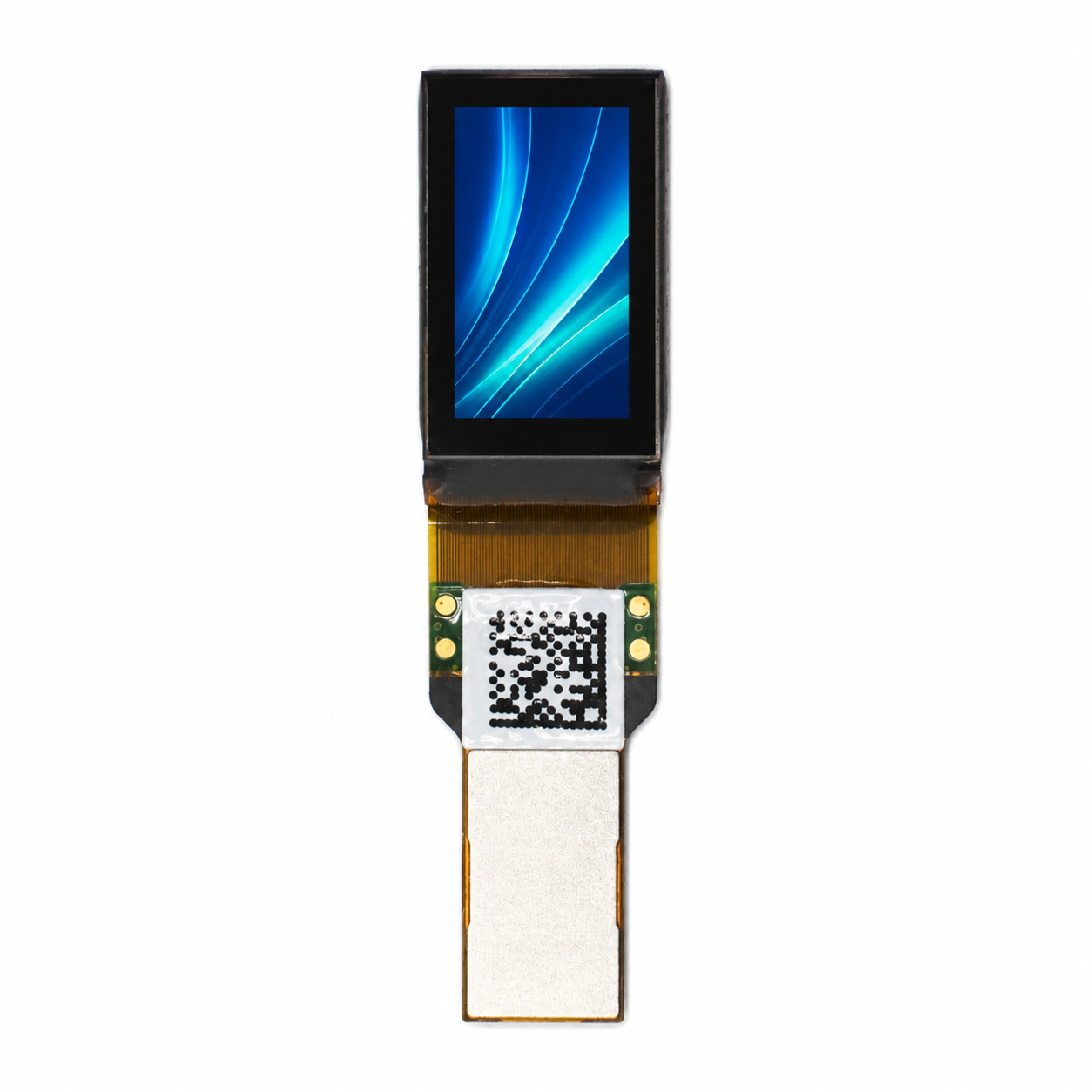
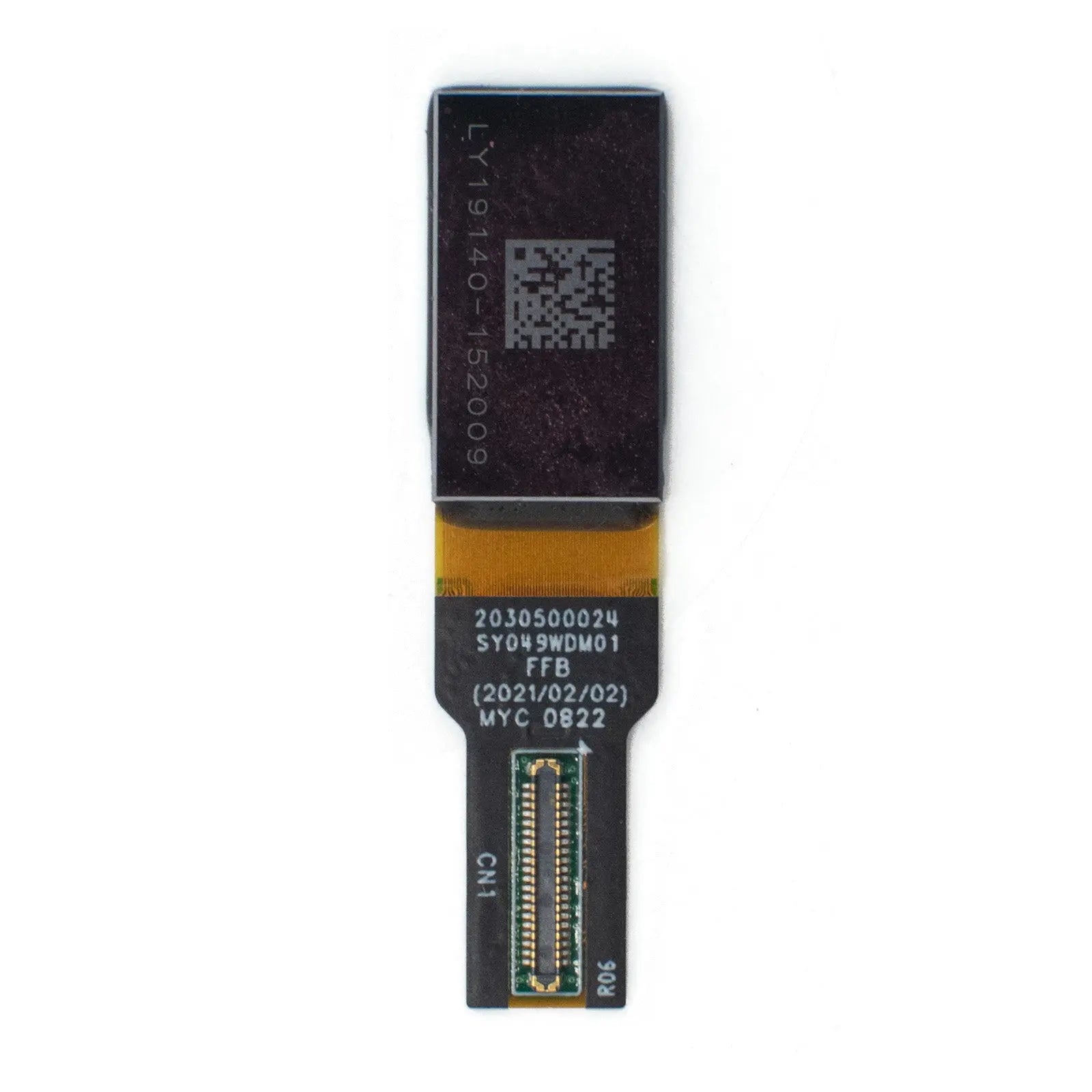
0.49" Micro OLEDoS Display 1920x1080 90Hz 1800nits - MIPI
- 💹 Enjoy a 20% discount for orders over 500
- 📉 A 15% discount is available for orders ranging from 200 to 499
- 🎁 A 10% discount is available for orders ranging from 50 to 199
- 🎁 A 5% discount is available when ordering 10-49
Interested in customizing this product? Get in touch with us.
Order samples, immediate delivery.
Factory bulk lead time: 3 weeks.
0.49" Micro OLEDoS Display 1920x1080 90Hz 1800nits - MIPI
- 💹 Enjoy a 20% discount for orders over 500
- 📉 A 15% discount is available for orders ranging from 200 to 499
- 🎁 A 10% discount is available for orders ranging from 50 to 199
- 🎁 A 5% discount is available when ordering 10-49
DM-OLED049-1002 · Micro OLEDoS Display Module
0.49-Inch Micro OLEDoS Display, 1920 × 1080, 90 Hz, 1800 Nits, MIPI Interface
This 0.49-inch Micro OLEDoS display module is designed for near-eye optical systems that require full HD resolution, high brightness, compact dimensions, and low module weight. It uses a silicon-based OLED architecture with integrated panel-driving and logic-driving circuits for AR glasses, electronic viewfinders, microscopes, industrial optics, medical visualization equipment, and compact head-mounted systems.
The module provides 1920(H) × 1080(V) resolution, 1800 cd/m² typical luminance, a 50,000:1 contrast ratio, 90% DCI-P3 color gamut, 60 Hz to 90 Hz operation, MIPI DSI video input, I2C control, and an approximate module weight of 1 g. Its active area measures 10.783 mm × 6.065 mm, with a pixel pitch of 5.616 μm × 5.616 μm and a calculated pixel density of approximately 4522 PPI.

Active Area: 10.783 mm × 6.065 mm
Pixel Pitch: 5.616 μm
Weight: Approximately 1 g
Optical Performance Data
Approximately 4522 PPI
The pixel density is calculated from 1920 pixels across the 10.783 mm active width and 1080 pixels across the 6.065 mm active height. This density helps minimize visible pixel structure when the panel image is magnified through a near-eye optical system.
1800 cd/m² Typical Luminance
The luminance level provides brightness margin for optical loss through lenses, prisms, magnifiers, and waveguide assemblies. Final eye-side brightness depends on optical transmission efficiency, coatings, eye-box design, image content, and driving conditions.
50,000:1 Contrast Ratio
Self-emissive OLED pixels can produce deep black image areas without an LCD backlight. This supports clearer dark-scene rendering in viewfinders, night-viewing equipment, inspection systems, and visualization devices.
90% DCI-P3 Color Gamut
The specified color coverage supports vivid image output in compact optical systems. Color-critical applications should validate white point, gamma, panel settings, optical coatings, and the completed optical stack.
Product Specifications
| Parameter | Specification | Engineering Note |
|---|---|---|
| Display Type | Micro-OLED / Si-OLED | OLED pixels are formed on a silicon backplane for compact, high-pixel-density near-eye display systems. |
| Display Size | 0.49-inch diagonal | Compact dimensions for AR optical engines, electronic viewfinders, and miniature imaging instruments. |
| Resolution | 1920(H) × 1080(V) | Full HD image output for interfaces, symbols, detailed viewfinder scenes, and imaging content. |
| Active Area | 10.783 mm × 6.065 mm | Used when calculating optical magnification, field of view, image position, and mechanical alignment. |
| Pixel Pitch | 5.616 μm × 5.616 μm | The small pixel pitch supports detailed image rendering in magnified optical systems. |
| Pixel Density | Approximately 4522 PPI | Calculated from the stated resolution and active area dimensions. |
| Luminance | 1800 cd/m² typical | Provides display-side brightness margin for losses through lenses, prisms, coatings, magnifiers, and waveguides. |
| Contrast Ratio | 50,000:1 | Supports deep black areas without the backlight leakage associated with LCD panels. |
| Color Gamut | 90% DCI-P3 | Final color performance depends on calibration, register settings, image processing, and the optical stack. |
| Frame Rate | 60 Hz to 90 Hz | The 90 Hz mode can improve motion smoothness in interactive and head-mounted viewing systems. |
| Interface | MIPI DSI + I2C | MIPI DSI carries video data, while I2C is used for register configuration and control. |
| MIPI Physical Layer | MIPI D-PHY v1.2, 1 port, 4 lanes, 1.0 Gbps per lane | The host controller must support the required lane configuration, timing, and compression mode. Full HD at 90 Hz may require DSC because protocol overhead reduces usable payload bandwidth. |
| Compression | VESA DSC v1.1 decoder, 3× and 3.75× compression ratios | Compression reduces MIPI bandwidth requirements for high-resolution, high-frame-rate video transmission. |
| Operating Voltage |
AVDD: 5.3–5.5 V; AVEE: −4 to −5.5 V; VDDI: 1.65–1.95 V |
Power sequencing, ramp timing, ripple, and discharge behavior must follow the official datasheet. |
| Power Consumption | 468 mW typical at 90 Hz, 1800 nits, full-white image | Consumption varies with luminance, frame rate, image content, temperature, and register settings. |
| Operating Temperature | −20°C to +70°C | System-level thermal performance should be confirmed in the final enclosure and optical assembly. |
| Storage Temperature | −40°C to +80°C | Relevant to warehousing, transportation, and non-operating product storage. |
| Weight | Approximately 1 g | The low panel weight helps limit optical-engine mass in wearable and portable systems. |
Interface, Compression and Driving Architecture
MIPI DSI Video Input
The module uses MIPI DSI for video transmission and supports MIPI D-PHY v1.2. Its four-lane configuration operates at up to 1.0 Gbps per lane. The host platform should be checked for lane count, clock configuration, display timing, DSC compatibility, and initialization sequence.
VESA DSC v1.1 Decoder
The integrated DSC decoder supports 3× and 3.75× compression ratios. Compression lowers the required transmission bandwidth for full HD output at higher frame rates. Compression settings, video timing, image stability, and visual quality should be tested together on the selected controller platform.
I2C Register Control
I2C is used for command and register configuration. Engineering tasks may include luminance adjustment, display-mode configuration, gamma settings, timing control, and panel-status management. Register values should follow the official datasheet and application documentation.
Electrical Design Checklist
Power Rails
Design for AVDD at 5.3–5.5 V, AVEE at −4 to −5.5 V, and VDDI at 1.65–1.95 V. Validate ripple, ramp timing, sequencing, shutdown behavior, rail tolerance, and discharge time before production.
Signal Integrity
Route MIPI differential pairs with controlled impedance, matched lengths, short stubs, a continuous ground reference, and reliable connector contact. Keep high-speed traces away from switching regulators and other noisy circuits.
Thermal Control
At 90 Hz, 1800 nits, and a full-white image, typical power consumption is specified as 468 mW. Thermal performance should be checked inside enclosed AR, EVF, and optical modules with limited heat-spreading area.
Validation Items
Test initialization, frame stability, brightness uniformity, color shift, EMI behavior, image retention, connector contact, and FPC reliability inside the final mechanical structure.
Application Fit by System Type
AR Glasses and Optical Engines
The 0.49-inch display size, approximate 1 g weight, 1800 cd/m² luminance, and full HD resolution can support compact AR optical-engine development. The high pixel density helps reduce visible pixel structure after magnification, while final eye-side brightness depends heavily on optical efficiency.
Electronic Viewfinders
The 60 Hz to 90 Hz frame-rate range and 50,000:1 contrast ratio support smooth preview images and deep black levels in camera viewfinders, inspection devices, telescopes, microscopes, and portable optical instruments.
Medical and Laboratory Visualization
Full HD resolution, OLED contrast, and 90% DCI-P3 coverage can support visualization prototypes, laboratory viewers, training systems, and compact medical optical equipment. Diagnostic or clinical use requires system-level verification and compliance with the applicable medical-device requirements.
Industrial Optical Equipment
The module can be evaluated for handheld inspection tools, thermal-imaging viewers, microscope systems, laser rangefinders, and compact measurement instruments that require a small display with high image detail.
OEM and ODM Integration Support
Engineering Materials
Available project support may include the datasheet, FPC drawing, electrical characteristics, interface requirements, power-rail information, initialization guidance, and display-integration consultation for qualified projects.
Customization Scope
Project-based customization may include FPC design, connector orientation, display-driving support, optical-matching discussions, firmware coordination, private labeling, packaging, and volume-production planning.
Sample and Volume Supply
Samples can be used for optical proof-of-concept work, electrical validation, and prototype builds. Before volume production, confirm lead time, lifetime targets, inspection criteria, packaging method, change-control requirements, and long-term supply planning.
Selection Notes for Engineers
Review the brightness budget, host-controller capability, power rails, thermal margin, optical alignment, and reliability targets before integrating this 0.49-inch Micro OLEDoS display into AR glasses, EVF modules, visualization systems, or industrial optical instruments.
Brightness Budget
Use the specified 1800 cd/m² typical luminance as the display-side reference. Eye-side brightness must account for waveguide efficiency, lens transmission, prism loss, coating reflection, polarizer loss, aperture size, and mechanical light leakage.
Host Controller Matching
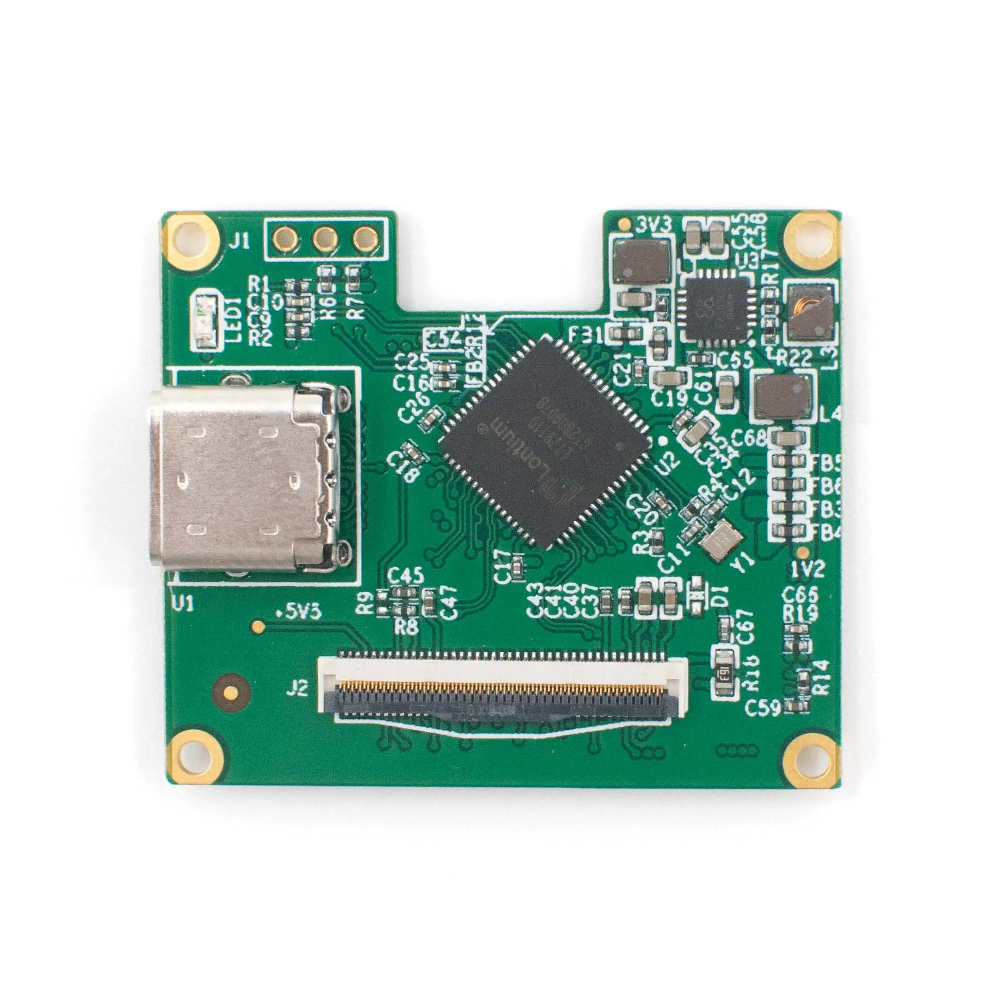
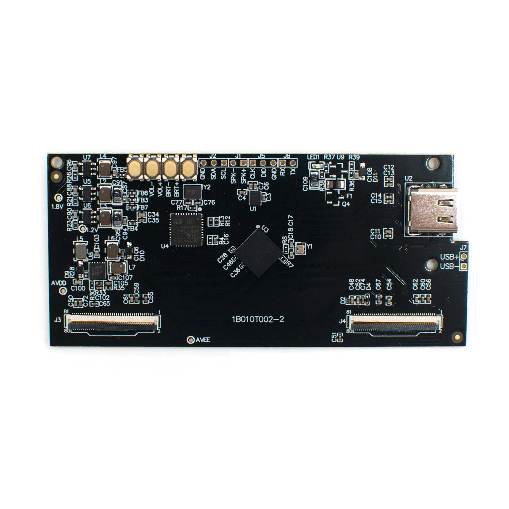
Confirm that the controller supports MIPI DSI, four-lane operation, the required video timing, I2C initialization, and DSC when compression is used. Test the display with the intended SoC before completing the PCB and optical design.
Power and Thermal Margin
The 468 mW typical condition is specified at 90 Hz, 1800 nits, and a full-white image. Product designs should include margin for sustained high-brightness interfaces, enclosed housings, limited airflow, and continuous operation.
Reliability Review
For long operating cycles, evaluate luminance decay, image retention, operating temperature, humidity exposure, vibration, storage conditions, FPC stress, and the system-level burn-in criteria.
Optical Alignment
Check the active-area position, optical center, display tilt, FPC exit direction, lens distance, image orientation, and mechanical tolerance before tooling.
Power-Rail Check
Verify AVDD at 5.3–5.5 V, AVEE at −4 to −5.5 V, and VDDI at 1.65–1.95 V for ripple, sequencing, startup timing, and shutdown behavior.
MIPI Layout
Route MIPI differential pairs with controlled impedance, matched lengths, short stubs, a clean reference ground, and stable connector contact.
Technical FAQ
What is the pixel density of this 0.49-inch Micro OLEDoS display?
The calculated pixel density is approximately 4522 PPI, based on 1920 pixels across the 10.783 mm active width and 1080 pixels across the 6.065 mm active height.
Does the display support 90 Hz operation?
Yes. The specified frame-rate range is 60 Hz to 90 Hz. For full HD operation at 90 Hz, the host controller, MIPI timing, DSC configuration, power design, and thermal design should be verified together.
Which interface does the module use?
The display uses MIPI DSI for video input and I2C for control. Its MIPI physical layer supports D-PHY v1.2, one port, four lanes, and up to 1.0 Gbps per lane.
Is display-stream compression supported?
Yes. The module integrates a VESA DSC v1.1 decoder and supports 3× and 3.75× compression ratios. The selected compression mode must be tested with the target host controller and video timing.
What should be checked before prototype production?
Check power sequencing, MIPI signal quality, DSC compatibility, I2C initialization, frame stability, luminance, thermal behavior, optical alignment, FPC routing, connector reliability, and product-lifetime requirements.
Download the Datasheet and Confirm Integration Details
Use the official datasheet to confirm the mechanical drawings, absolute maximum ratings, recommended operating conditions, interface timing, power-rail requirements, register settings, and reliability limits before PCB layout or optical-engine tooling.
For OEM and ODM projects, confirm sample availability, volume pricing, production lead time, customization scope, inspection criteria, lifetime requirements, and long-term supply planning with the engineering team.
Download Official DatasheetProduct FAQs
Key technical and purchasing guidance for product evaluation, integration planning, samples, and volume orders.