











1.03" Micro OLEDoS Display 2560x2560 90Hz 3000nits - MIPI
- 💹 Enjoy a 20% discount for orders over 500
- 📉 A 15% discount is available for orders ranging from 200 to 499
- 🎁 A 10% discount is available for orders ranging from 50 to 199
- 🎁 A 5% discount is available when ordering 10-49
Interested in customizing this product? Get in touch with us.
Order samples, immediate delivery.
Factory bulk lead time: 3 weeks.
1.03" Micro OLEDoS Display 2560x2560 90Hz 3000nits - MIPI
- 💹 Enjoy a 20% discount for orders over 500
- 📉 A 15% discount is available for orders ranging from 200 to 499
- 🎁 A 10% discount is available for orders ranging from 50 to 199
- 🎁 A 5% discount is available when ordering 10-49
DM-OLED103-1010 · Micro OLEDoS Display Module
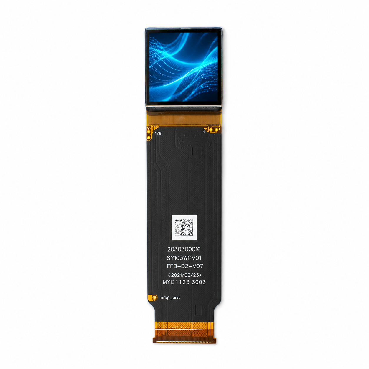
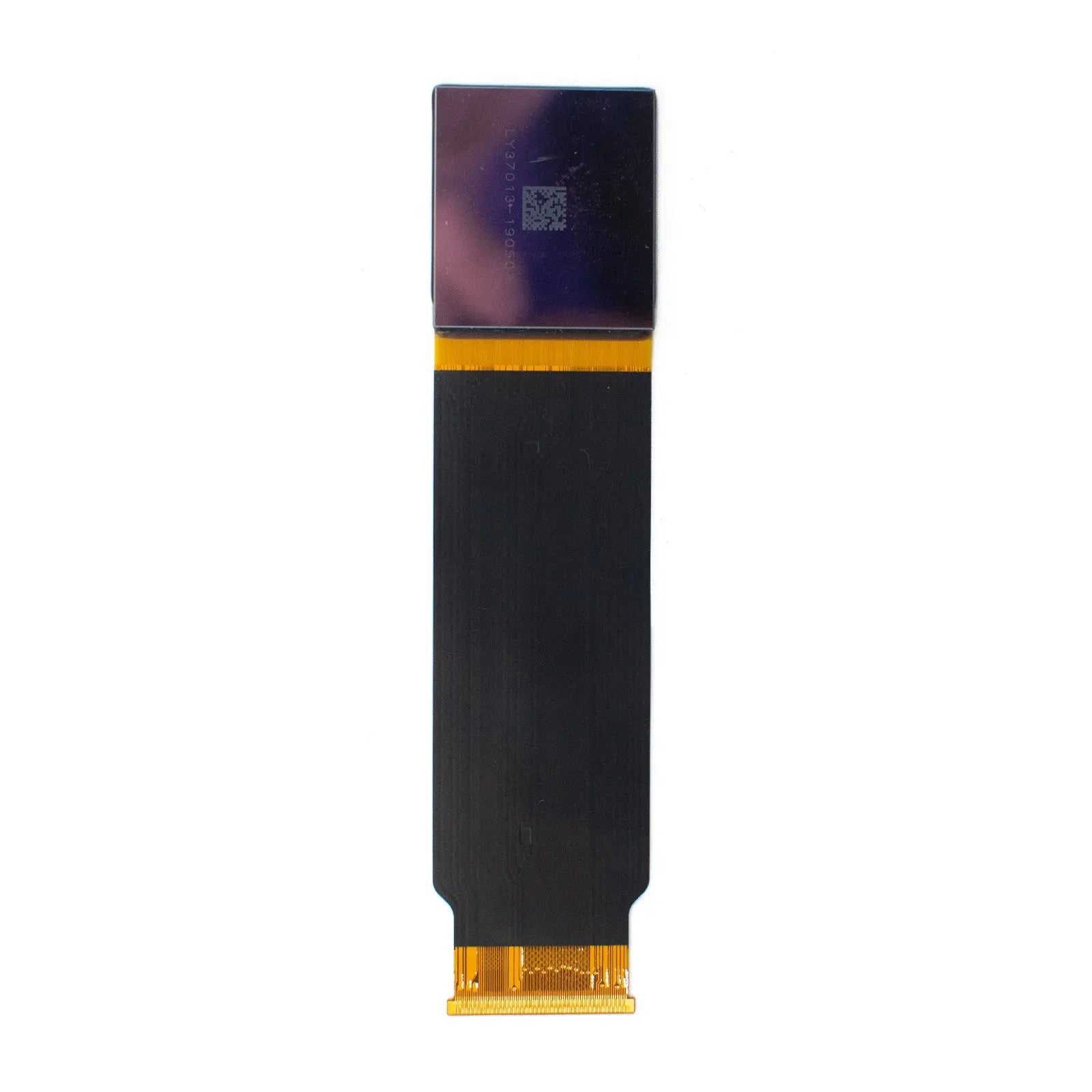
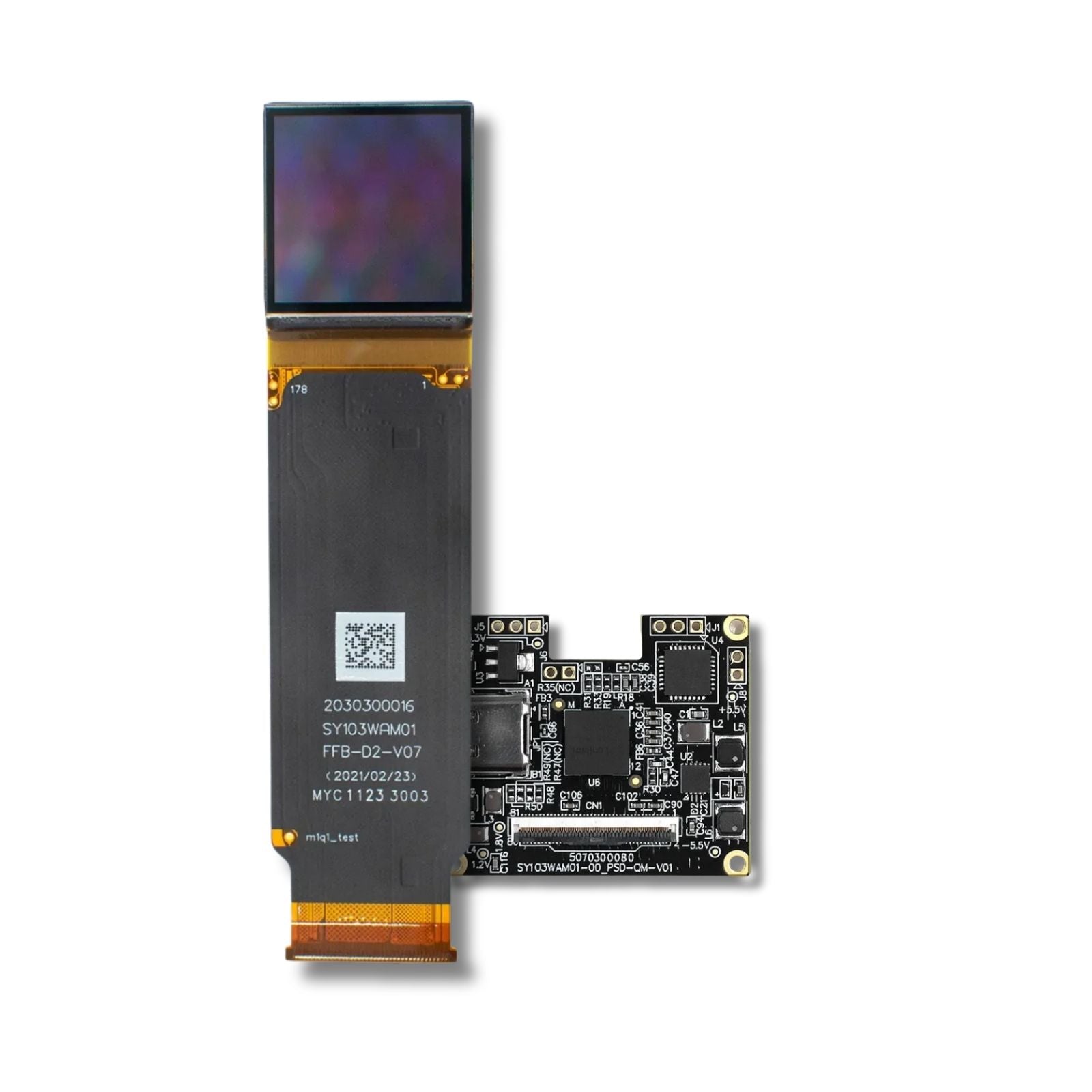
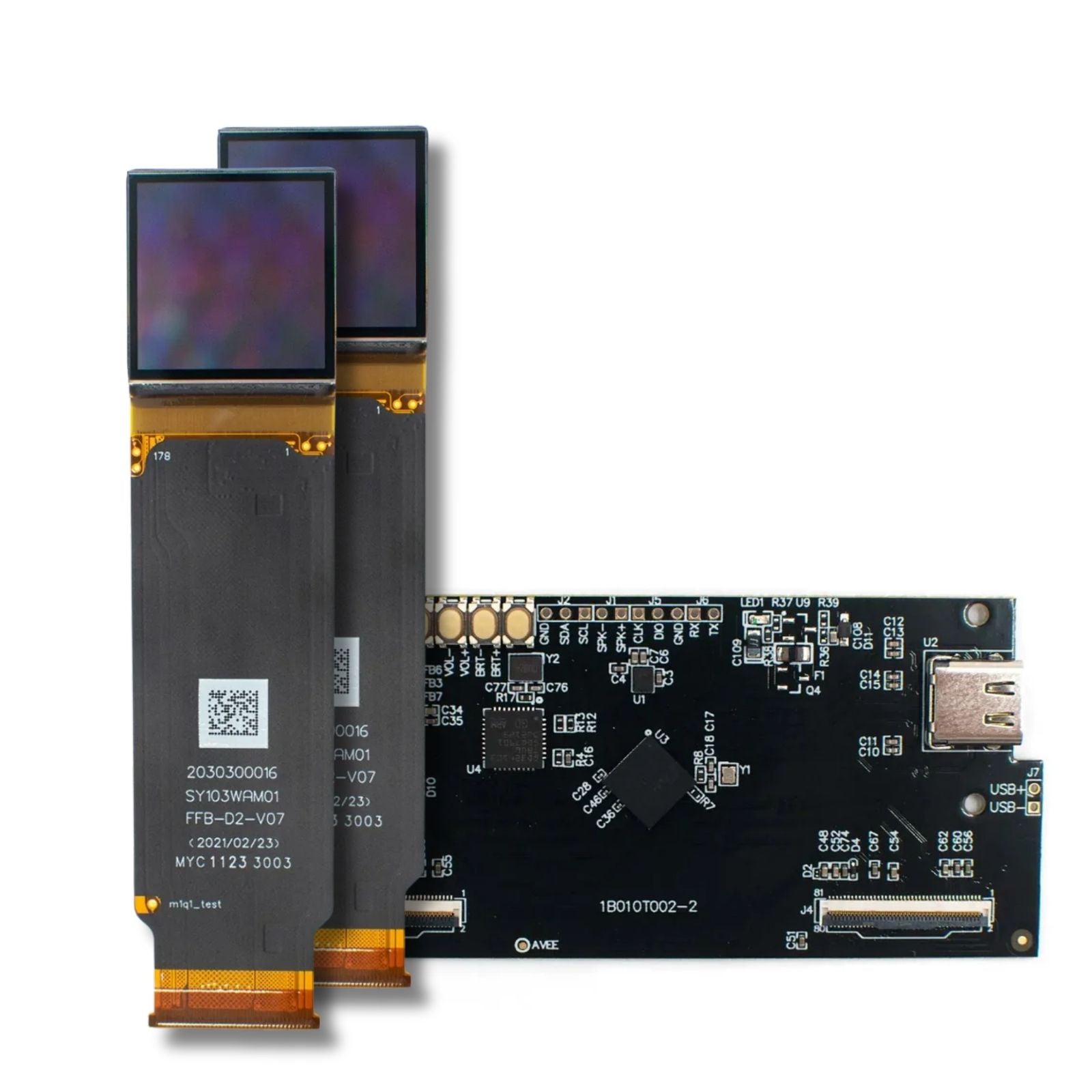
1.03" Micro OLEDoS Display, 2560×2560, 90 Hz, 3000 nits – MIPI
This 1.03-inch Micro OLEDoS display module is built for compact near-eye and viewfinder optical systems that require high pixel density, high panel luminance, and a silicon-based active-matrix architecture.
According to the product datasheet, the module provides 2560(H) × 2560(V) resolution, an 18.432 mm × 18.432 mm usable display area, 7.2 μm × 7.2 μm pixel size, RGBπ pixel arrangement, 3000 cd/m² typical luminance, a 500,000:1 typical contrast ratio, MIPI + I2C interfaces, and a module weight of 2 g.
2560×2560
Real RGB Resolution
3000 cd/m²
Typical Panel Luminance
500,000:1
Typical Contrast Ratio
60–90 Hz
Mode-Dependent Frame Rate

Usable Area: 18.432 mm × 18.432 mm
Pixel Size: 7.2 μm
Weight: 2 g
Datasheet-Based Display Parameters
Silicon Backplane Architecture
The panel is based on single-crystal silicon transistors and integrates panel-driver and logic-driver functions, supporting a compact, high-resolution microdisplay structure for near-eye optical designs.
Near-Eye Image Density
The 2560×2560 square format and 7.2 μm pixel pitch provide dense image sampling for magnified optical systems, helping reduce visible pixel structure after optical enlargement.
Brightness Budget Required
Use 3000 cd/m² as the panel-side typical luminance reference. Eye-side brightness must be calculated after lens, waveguide, prism, coating, polarizer, and combiner losses.
Temperature Compensation
The module supports temperature compensation. Its operating temperature range is -20°C to +70°C, while its storage temperature range is -40°C to +80°C.
Optical, Electrical & Mechanical Specifications
| Parameter | Specification | Engineering Note |
|---|---|---|
| Resolution | 2560(H) × 2560(V) | Square high-resolution format for near-eye display and viewfinder optical systems. |
| Number of Dots | 19.66M | 2560 × 2560 × 3 subpixel dot count according to the datasheet. |
| Usable Display Area | 18.432 mm × 18.432 mm | Approximately 1.03-inch diagonal usable display area for optical alignment and module design. |
| Pixel Size | 7.2 μm × 7.2 μm | Small pixel pitch supports dense image sampling in magnified optical paths. |
| Pixel Arrangement | RGBπ Type | Full-color subpixel arrangement defined in the product datasheet. |
| Luminance | 3000 cd/m² Typical | Panel-side luminance under the specified optical measurement conditions. |
| Contrast Ratio | 500,000:1 Typical | Datasheet typical value. System-level contrast also depends on the optical engine, stray light, and ambient conditions. |
| Uniformity | >85% | Defined by the datasheet measurement conditions at the highest gray level and 100% duty emission. |
| Color Gamut | 90% DCI-P3 Typical | Perform module-level color calibration after optical assembly when evaluating the finished system. |
| Gray Levels | 256 | Datasheet-listed gray-level depth for the display driving configuration. |
| Frame Rate | 60–90 Hz | Mode-dependent. The datasheet notes that 1920×1920 input with 1.33× scaling and DSC can reach up to 90 Hz. A 2560×2560 input with DSC is listed at up to 75 Hz. |
| Interface | MIPI + I2C | MIPI D-PHY v1.2, one-port or two-port operation, 4 or 8 lanes, up to 1.0 Gbps per lane, MIPI DSI video mode, and I2C control. |
| DSC & Scaling | VESA DSC v1.1 | Supports an integrated DSC decoder with a 3× compression ratio, together with 1.33× and 2× scaling modes. |
| Operating Voltage | VDDI 1.8 V | Analog rails include AVDD at 5.8–6.0 V and AVEE at -4.0 to -5.5 V. Confirm the required rail sequence before releasing the PCB design. |
| Power Consumption | 2400 mW | Datasheet condition: 3000 nits, 100% duty, 1920×1920 input, 1.33× scaling, no DSC, and 72 Hz operation. |
| Temperature Range | -20°C to +70°C | Storage range: -40°C to +80°C. Validate the actual enclosure temperature during continuous high-brightness operation. |
| Module Weight | 2 g | Low module weight supports compact optical assemblies and head-mounted display prototypes. |
MIPI Integration Details
MIPI D-PHY v1.2
The module supports MIPI D-PHY v1.2 with one-port or two-port operation. Designers should select 4-lane or 8-lane routing based on bandwidth, connector design, PCB stack-up, and host processor capability.
VESA DSC v1.1 Decoder
The integrated VESA DSC v1.1 decoder supports a 3× compression ratio. Final DSC parameters and visual performance should be validated with the selected host platform.
Scaling Modes
The module supports 1.33× scaling from 1920×1920 to 2560×2560 and 2× scaling from 1280×1280 to 2560×2560. These modes allow designers to balance rendering load, bandwidth, frame rate, and system power.
Integration Check Before EVT Board Release
Confirm the MIPI lane count, connector pin assignment, power-rail sequencing, negative-voltage generation, ground return path, display initialization timing, I2C control, DSC configuration, FPC bend radius, and thermal derating.
Application Fit by Engineering Requirement
AR / VR Head-Mounted Display Prototypes
The 1.03-inch square format, 2 g module weight, and high pixel density can be evaluated for compact near-eye optical engines. Final eye-side brightness and thermal margin must be calculated at the complete system level.
Electronic Viewfinders
The 2560×2560 resolution, OLED contrast, and MIPI video input support engineering evaluation for camera EVFs, microscope viewfinders, inspection viewers, and portable optical instruments.
Medical / Clinical Visualization Evaluation
The module may be evaluated as a display component for visualization equipment. Medical-device safety, reliability, optical performance, and regulatory compliance must be verified by the finished-product developer.
Industrial Optical Instruments
The compact display area, high contrast, MIPI interface, and wide storage-temperature range make the module relevant for inspection equipment, measurement instruments, professional viewfinders, and optical terminals.
Design Review Checklist for OEM Projects
Optical Path Budget
Calculate eye-side brightness after lens, waveguide, prism, coating, combiner, polarizer, and mechanical light-leakage losses.
Host Controller Matching
Verify MIPI DSI video mode, D-PHY lane configuration, 1.0 Gbps per lane operation, DSC support, scaling mode, and I2C initialization.
Power Rail Sequencing
Design stable VDDI, AVDD, and AVEE rails. Confirm ramp timing, ripple, transient response, startup order, and shutdown sequence.
Thermal Validation
Check panel and enclosure temperatures during high-brightness, continuous operation under final mechanical packaging conditions.
Image Calibration
Validate gamma, brightness adjustment, scanning direction, sequential or global emission behavior, color consistency, and image-retention risk after assembly.
Technical Resources & Product Evidence
Official Datasheet
Use the datasheet to review mechanical drawings, electrical ratings, interface timing, MIPI settings, I2C controls, register configuration, optical measurement conditions, and reliability limits before PCB layout or optical tooling.
Evidence-Based Product Page
This page focuses on measurable product information, including resolution, usable area, pixel size, luminance, contrast ratio, color gamut, frame-rate conditions, interfaces, voltage rails, power conditions, temperature range, and the downloadable datasheet.
OEM / ODM Engineering Support
Project support may include display selection, FPC customization, optical-module matching, driver-board discussion, initialization support, sample evaluation, volume pricing, and long-term supply planning.
Request Datasheet Review, Samples, or OEM Integration Support
Share your target input resolution, MIPI host platform, optical architecture, eye-side brightness target, operating environment, expected annual quantity, and sample schedule.
The engineering team can help verify display compatibility, interface feasibility, mechanical integration, power requirements, and datasheet details before prototype design.
Product FAQs
Key technical and purchasing guidance for product evaluation, integration planning, samples, and volume orders.