









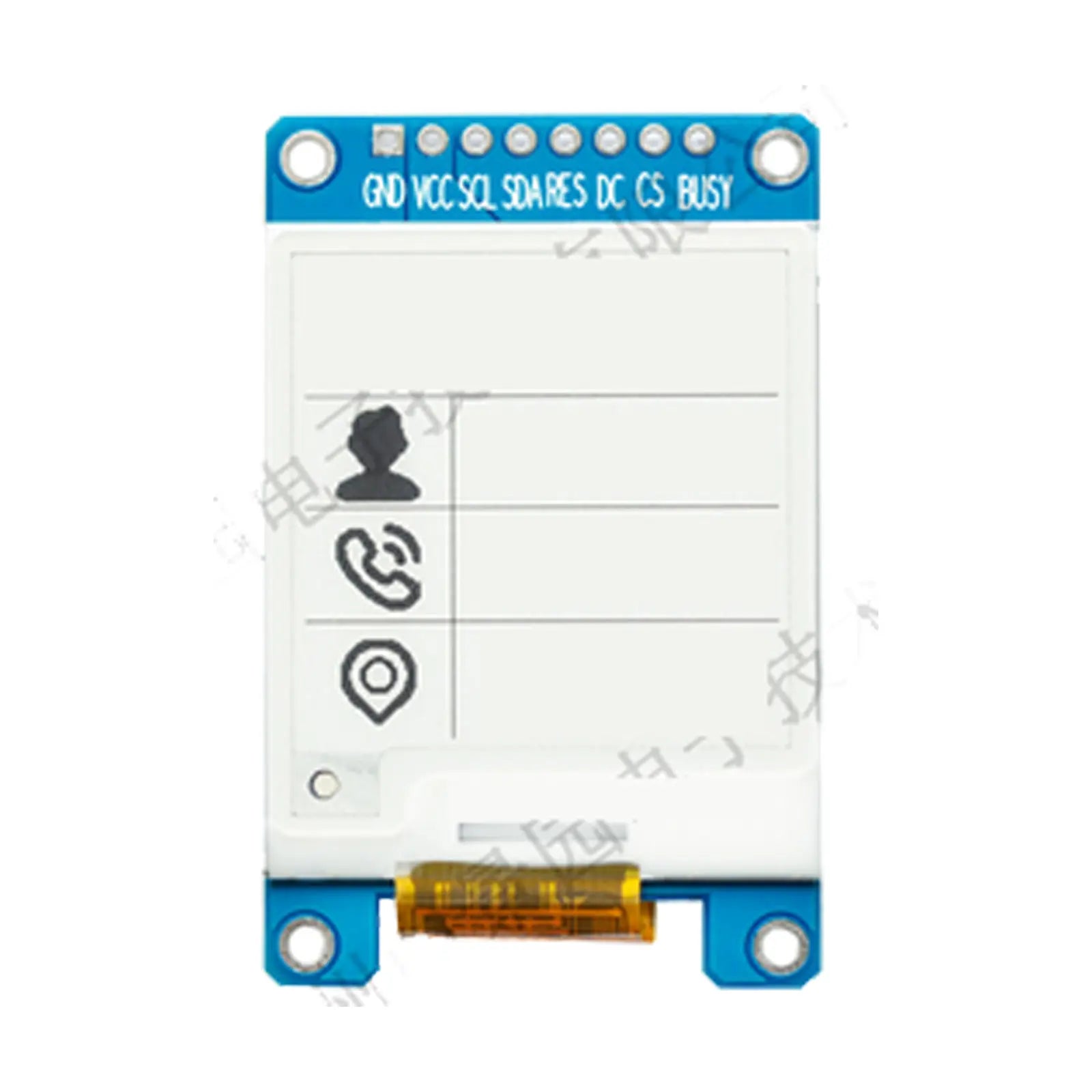
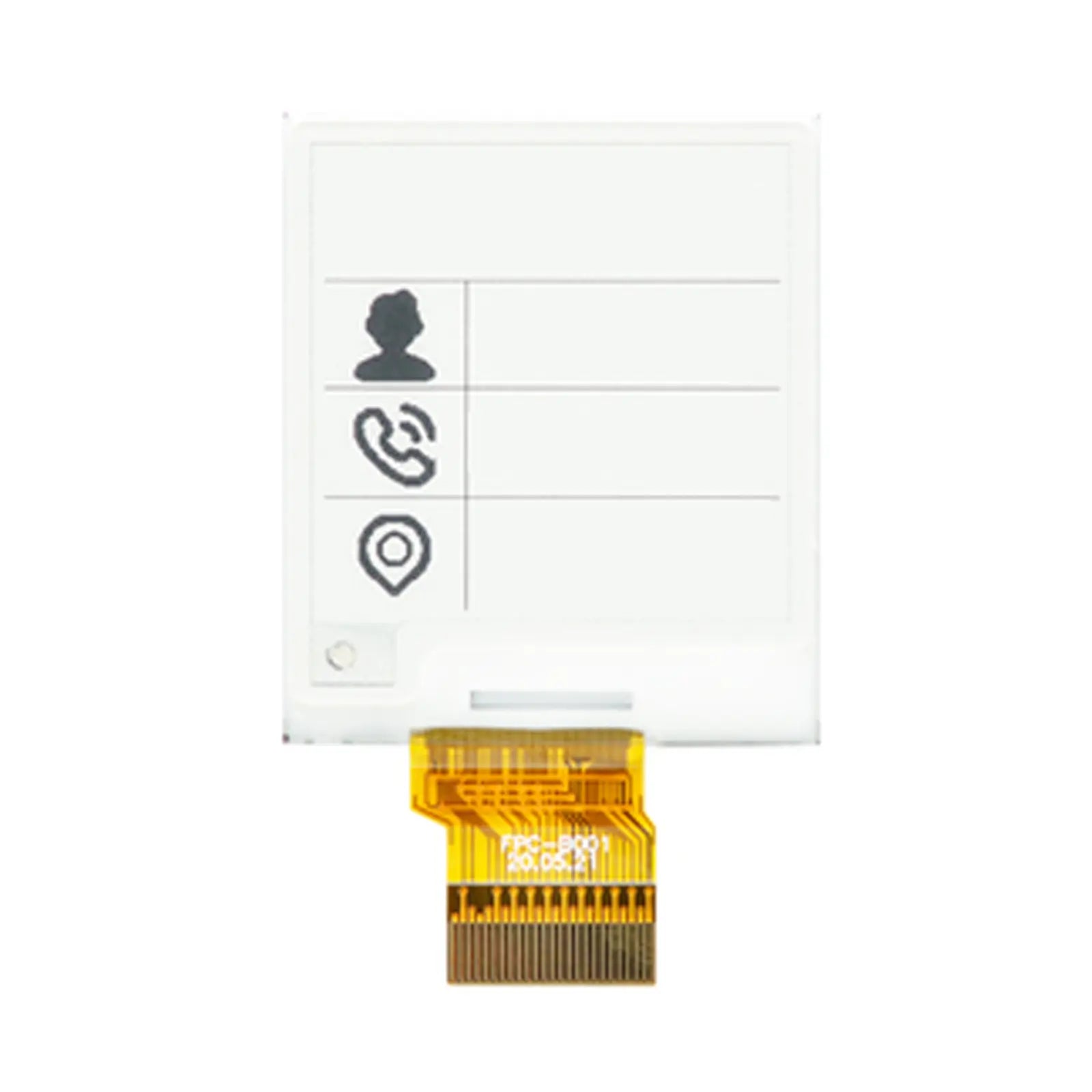
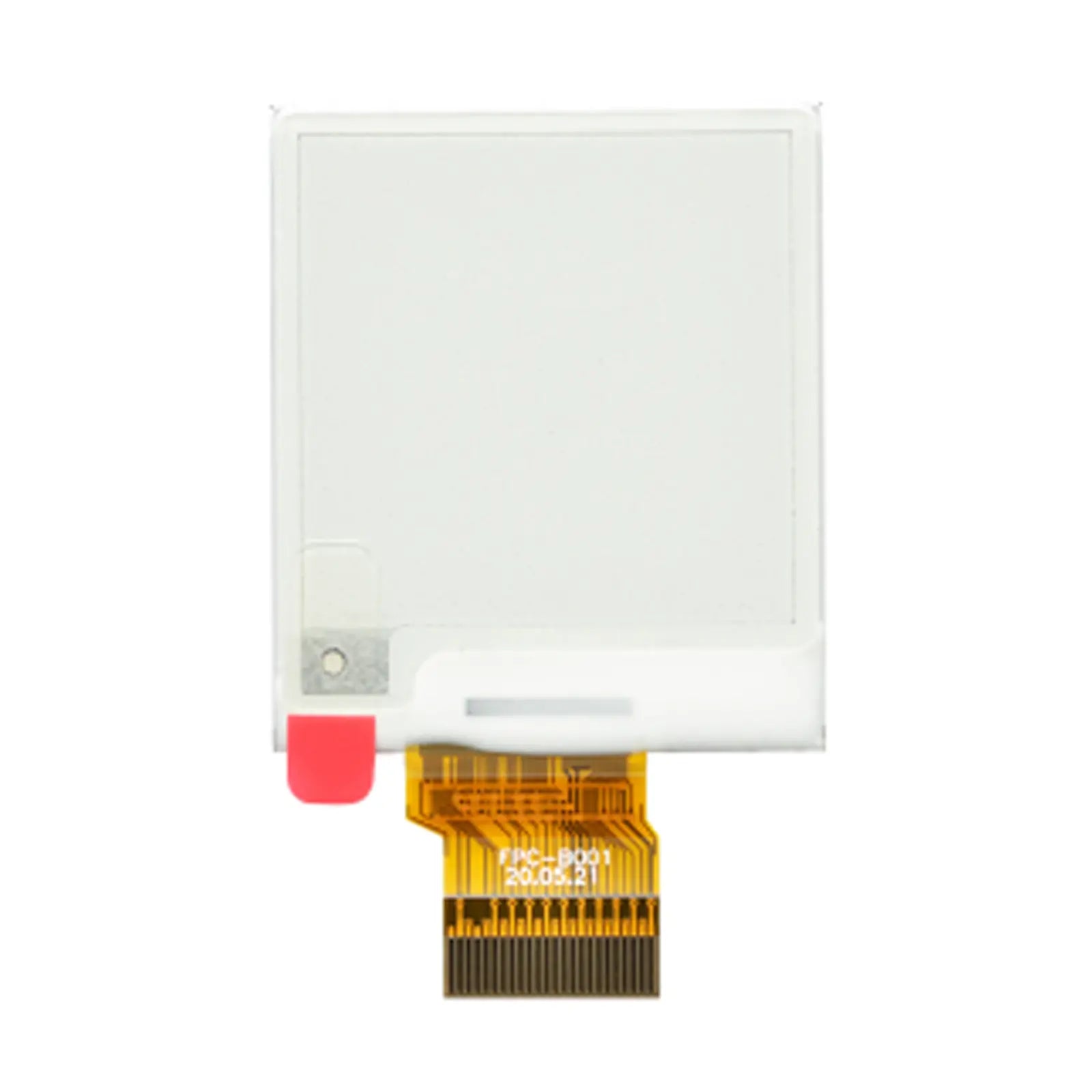
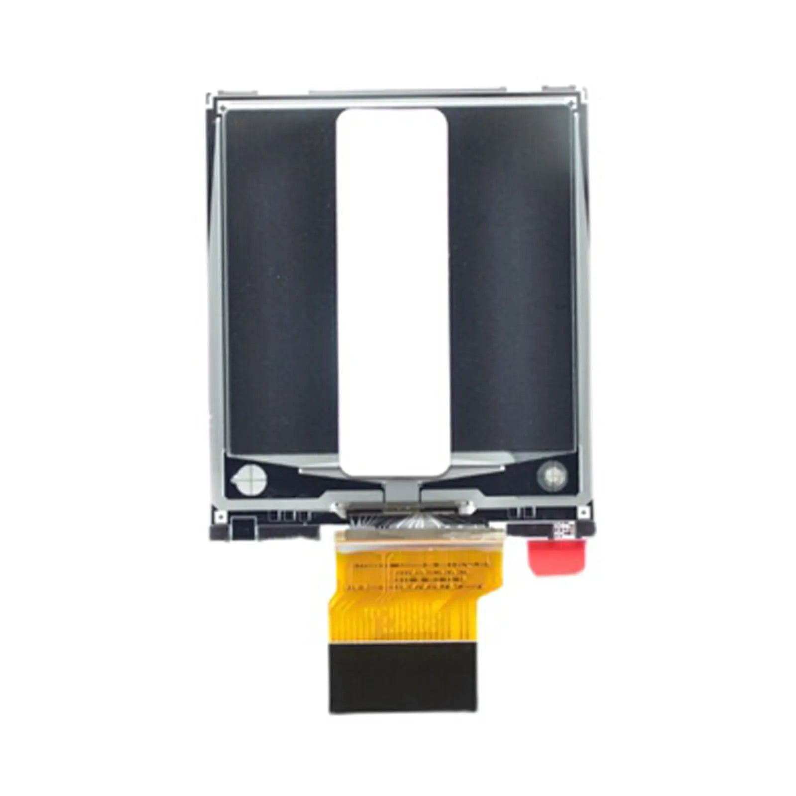
1.54" 200×200 E-Paper Display
- 💹 Enjoy a 20% discount for orders over 500
- 📉 A 15% discount is available for orders ranging from 200 to 499
- 🎁 A 10% discount is available for orders ranging from 50 to 199
- 🎁 A 5% discount is available when ordering 10-49
Interested in customizing this product? Get in touch with us.
Order samples, immediate delivery.
Factory bulk lead time: 3 weeks.
1.54" 200×200 E-Paper Display
- 💹 Enjoy a 20% discount for orders over 500
- 📉 A 15% discount is available for orders ranging from 200 to 499
- 🎁 A 10% discount is available for orders ranging from 50 to 199
- 🎁 A 5% discount is available when ordering 10-49
Resources & Downloads
1.54" 200×200 E-Paper Display with 3-Wire / 4-Wire SPI
DM-EPD154-012 is a compact active-matrix electrophoretic display with a 200×200 pixel matrix, a 27.0×27.0 mm active area, an SSD1681 display driver, and selectable 3-wire or 4-wire SPI communication.
The reflective, bi-stable display retains the last image without continuous panel power. Its published 3-second image update time, all-view readability, and low operating power support compact battery-powered and intermittently updated display designs.
Document basis: Product data on this page is summarized from the DM-EPD154-012 display datasheet and the SSD1681 controller documentation. Use the current model datasheet and mechanical drawing when finalizing the PCB, connector, and enclosure.

Verified Technical Specifications
The table below presents the published product parameters in a compact format for component selection and design review.
| Parameter | Specification | Unit |
|---|---|---|
| Diagonal Size | 1.54 | inch |
| Display Resolution | 200 × 200 | pixels |
| Pixel Density | 184 | DPI |
| Active Area | 27.0 × 27.0 | mm |
| Outline Dimensions | 31.80 × 37.32 × 0.98 | mm |
| Weight | 2.18 ± 0.5 | g |
| Logic Supply Voltage (VCI) | 2.2 to 3.7 (Typ. 3.0) | V |
| Core Logic Voltage (VDD) | 1.7 to 1.9 (Typ. 1.8) | V |
| White Reflectivity | 30% (Min), 35% (Typ) | % |
| Image Update Time | 3 | sec |
| Operating Temperature | 0 to +50 | °C |
| Storage Temperature | -25 to +70 | °C |
| Interface | 3-wire / 4-wire SPI | - |
| Driver IC | SSD1681 | - |
Display Architecture and Key Features
The panel combines the display matrix and controller functions needed for a compact reflective E-paper design. The points below focus on information used during product selection and integration.
Reflective, Bi-Stable E-Paper
The display uses ambient light rather than a backlight and can retain the last image after panel power is removed. Power is mainly required during image updates and controller activity.
3-Second Update
The published image update time is 3 seconds. Refresh behavior should be evaluated under the intended temperature and waveform conditions.
Reflective Readability
White reflectivity is specified at 30% minimum and 35% typical, with an 8:1 minimum contrast ratio under the documented measurement conditions.
Published Power Figures
Typical operating current is listed as 1.5 mA at 3.0 V. Sleep current with RAM retention is listed as 20 µA, and deep-sleep power is listed as 0.003 mW under the documented conditions.
Optical and Electrical Details
These published values help define the host power design, image-update expectations, and optical approval criteria.
Optical Performance
Power and Logic
SPI Interface and FPC Signal Groups
DM-EPD154-012 uses a 24-contact FPC and supports 3-wire or 4-wire SPI through the BS1 selection pin. The module datasheet should be followed for the complete pin order, external components, power sequence, and waveform initialization.
Interface Selection
4-wire SPI: SCL, SDA, D/C#, and CS# provide 8-bit command and data transfer.
3-wire SPI: Each transfer uses 9 bits, with the first bit identifying command or display data.
The published maximum SPI clock is 20 MHz. Final timing must follow the current module and SSD1681 documentation.
Mechanical Integration Summary
Use the full mechanical drawing for enclosure clearances, FPC routing, connector position, stiffener area, and the relationship between the panel outline and the active pixel area.
Published Reliability and Environmental Conditions
These documented test conditions help customers review environmental tolerance before sample evaluation and final product design. They do not replace application-level validation in the finished device.
Environmental Review
The normal operating range is 0°C to +50°C, and the storage range is -25°C to +70°C. E-paper update speed and optical appearance can vary with temperature, so evaluate samples under the intended use conditions.
Integration Checklist Before Ordering
Review the display as a complete panel, not only as an SSD1681 controller selection. The module datasheet defines the actual mechanical outline, FPC pin order, voltage network, and operating limits.
Reference Order for Design Review
1. Current DM-EPD154-012 datasheet and drawing
2. Approved physical sample
3. SSD1681 controller documentation
4. Product-page summary
Mechanical fit: Confirm the panel outline, active area, FPC route, connector location, stiffener clearance, and enclosure window.
Host logic: Verify VCI, VDDIO, input thresholds, reset timing, and whether level translation is required.
Power sequence: Follow the module reference circuit, external component values, discharge sequence, and deep-sleep instructions.
Firmware: Validate SPI mode, BUSY handling, initialization, RAM addressing, update sequence, and temperature selection.
Optical approval: Check contrast, white-state appearance, viewing conditions, protective window material, and possible reflections.
Connector matching: Match the 24-contact, 0.50 mm-pitch FPC to the selected ZIF connector and verify the contact orientation and insertion direction.
Typical Application Directions
The combination of image retention, reflective readability, compact size, and low update power can suit products that display information intermittently rather than continuously.
Electronic Shelf Labels
Compact price, product, and inventory labels that update periodically and retain the displayed image between updates.
Portable Instruments
Battery-powered meters and handheld devices that require a clear status display with infrequent content changes.
Smart Sensors
Local sensor readouts and IoT nodes where the display may remain unchanged for long periods between measurements.
Compact Status Devices
Wearable, identification, scheduling, and equipment-status products where thickness and image retention are design priorities.
Common Questions Before Ordering
Does the image remain visible when power is removed?
Yes. The panel is bi-stable and retains the last displayed image without continuous panel power. Power is still required for updates, controller operation, and the correct shutdown sequence.
What is the difference between 3-wire and 4-wire SPI?
In 4-wire mode, D/C# is a separate command-data signal. In 3-wire mode, each transfer uses a 9-bit format in which the first bit identifies command or data. BS1 selects the interface mode.
Is a touch panel included?
No touch function is documented in the supplied product information. Treat DM-EPD154-012 as a non-touch display unless a separate touch configuration is confirmed before ordering.
Does the display include a backlight?
No backlight is specified. The display is reflective and depends on ambient light for readability. Evaluate the final enclosure window and lighting conditions with a physical sample.
Can a generic SSD1681 code example be used without changes?
Controller documentation is a reference, but final firmware must match the DM-EPD154-012 pin configuration, power sequence, waveform settings, display RAM mapping, BUSY behavior, and update procedure.
What power figures are published?
The product documentation lists 1.5 mA typical operating current at 3.0 V, 20 µA sleep current with RAM retention, and 0.003 mW deep-sleep power under the stated conditions. Actual system consumption also depends on the refresh sequence, external components, and host design.
What temperature range should be used for product design?
The published operating range is 0°C to +50°C and the storage range is -25°C to +70°C. Sample testing is recommended because E-paper update behavior and optical appearance can vary with temperature.
What connector format should be matched?
The mechanical drawing shows a 24-contact FPC with 0.50 mm pitch. Confirm the contact side, connector height, locking style, and insertion direction before releasing the PCB layout.
Download Official Technical Documents
Use the display datasheet to confirm dimensions, FPC pin assignment, electrical limits, optical data, reference circuits, reliability conditions, and handling requirements. Use the SSD1681 document for controller commands, RAM operation, temperature functions, waveform storage, and interface timing.