









16x2 Character LCD STN Transflective - SPI, I2C
- 💹 Enjoy a 20% discount for orders over 500
- 📉 A 15% discount is available for orders ranging from 200 to 499
- 🎁 A 10% discount is available for orders ranging from 50 to 199
- 🎁 A 5% discount is available when ordering 10-49
Interested in customizing this product? Get in touch with us.
Order samples, immediate delivery.
Factory bulk lead time: 3 weeks.
16x2 Character LCD STN Transflective - SPI, I2C
- 💹 Enjoy a 20% discount for orders over 500
- 📉 A 15% discount is available for orders ranging from 200 to 499
- 🎁 A 10% discount is available for orders ranging from 50 to 199
- 🎁 A 5% discount is available when ordering 10-49
Resources & Downloads
16×2 STN Transflective Character LCD
DM-LCD1602-430 is
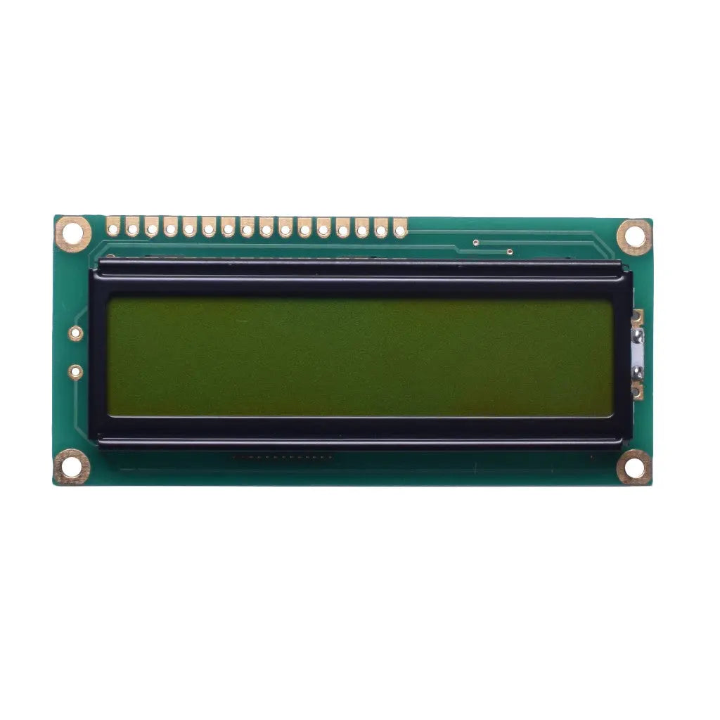
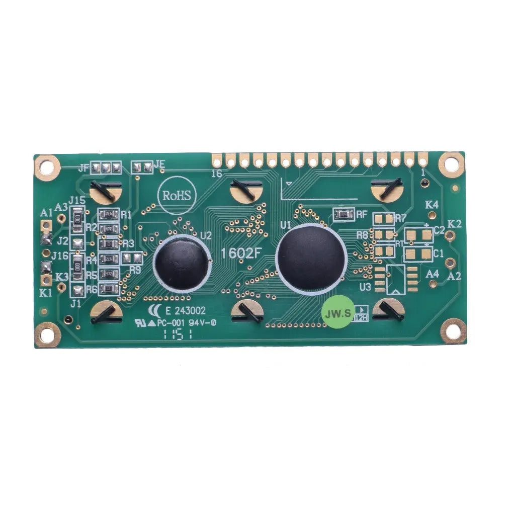
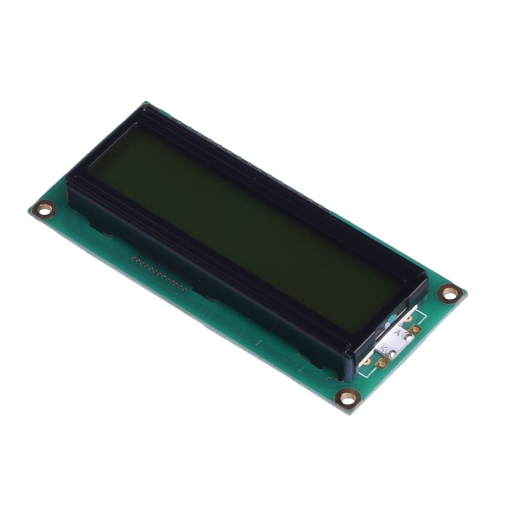
a 16-character × 2-line STN positive, yellow-green, transflective LCD module with SPI interface. DM-LCD1602-431 is the I2C interface version. Both modules use the DM4301C controller IC and have an 80.0 × 36.0 × 13.2 mm (MAX) module dimension.

Technical Specifications
Specifications listed in the DM-LCD1602-430 and DM-LCD1602-431 data sheets.
| Parameter | Specification |
|---|---|
| Product Model | DM-LCD1602-430 (4-SPI) / DM-LCD1602-431 (I2C) |
| Display Format | 16 characters × 2 lines |
| Display Mode | STN Positive, Yellow Green, Transflective |
| Module Dimension | 80.0 × 36.0 × 13.2 mm (MAX) |
| Controller IC | DM4301C |
| Interface | 4-SPI (DM-LCD1602-430) / I2C (DM-LCD1602-431) |
| Power Supply (VDD) | 5.0V typical (4.5V to 5.5V range) |
| Supply Current (IDD) | 1.2 mA typical (1.0 to 1.5 mA) at VDD = 5.0V |
| View Direction | 6:00 |
| Duty | 1/16 |
| Backlight | Yellow Green LED, 4.1V typical (3.9 to 4.3V), 130 mA typical (117 to 156 mA) |
| Input Voltage Low (VIL) | VSS to 0.6V (4-SPI) / −0.3V to 0.55V (I2C) |
| Input Voltage High (VIH) | 0.7 × VDD to VDD (4-SPI) / 2.5V to VDD (I2C) |
| Contrast Ratio | 3 (Typ) |
| Response Time | 300 ms (Typ), 400 ms (Max) at 25°C |
| Luminance (without LCD) | 270 cd/m² (Typ), 216 cd/m² (Min) |
| View Angles | 20° top, 40° bottom, 30° left, 30° right |
| Operating Temperature | −20°C to +70°C |
| Storage Temperature | −30°C to +80°C |
| Weight | 32.7 g (DM-LCD1602-430) / 32.3 g (DM-LCD1602-431) |
Display and Controller
Display mode: STN Positive, Yellow Green, Transflective. Backlight: Yellow Green LED.
The DM4301C CGROM has 256 characters in 5 × 8-dot format. The controller documentation describes CGRAM for user-defined character data and DDRAM that stores a maximum of 80 characters.
View direction is 6:00 and duty is 1/16. The module data sheet provides a serial-interface initialization flow at fosc = 540 kHz; at 540 kHz, the controller documentation specifies a 185 ms cursor-blink interval.
Optical & Electrical Performance
Electrical and optical characteristics listed in the module data sheets.
Optical Characteristics
Electrical Characteristics
Interface & Pin Configuration
The DM-LCD1602-430 data sheet lists SPI interface and the DM-LCD1602-431 data sheet lists I2C interface. Their pin descriptions are shown below. The DM4301C controller documentation lists IIC, 4SPI, 4-bit bus, and 8-bit bus interface types.
DM-LCD1602-430
4-SPI InterfaceDM-LCD1602-431
I2C Interface4-SPI
DM-LCD1602-430 pins: RS, CSB, SCLK, and SID.
I2C
DM-LCD1602-431 pins: SA0, SA1, CSB, SDA, and SCL.
4-bit Bus
DM4301C controller interface type. DM-LCD1602-430 pins 5–11 are NC; DM-LCD1602-431 pins 4–6 and 9–11 are NC.
8-bit Bus
DM4301C controller interface type. DM-LCD1602-430 pins 5–11 are NC; DM-LCD1602-431 pins 4–6 and 9–11 are NC.
Environmental Test Conditions
Reliability test conditions listed in the module data sheet. The function test shall be conducted after 4 hours of storage at normal temperature and humidity after removal from the test chamber.
| Test Item | Condition | Duration |
|---|---|---|
| High Temp Storage | 80°C | 200 hrs |
| Low Temp Storage | −30°C | 200 hrs |
| High Temp Operation | 70°C | 200 hrs |
| Low Temp Operation | −20°C | 200 hrs |
| High Temperature/Humidity Operation | 60°C, 90% RH; no-load condition; polarizer excluded; then dried at normal temperature | 96 hrs |
| Thermal Shock | −20°C for 30 min → 25°C for 5 min → +70°C for 30 min | 10 cycles |
| Vibration Test | 1.5mm total fixed amplitude; 10–55 Hz; one cycle 60 s | 16 min per axis (X/Y/Z) |
| ESD Test | VS=800V, RS=1.5kΩ, CS=100pF | 1 time |
Interface and Controller Notes
Statements below are taken from the DM-LCD1602-430, DM-LCD1602-431, and DM4301C documents.
Module Interfaces
DM-LCD1602-430: SPI interface. DM-LCD1602-431: I2C interface. Both module data sheets list pins 1–16.
Controller Interface Types
The DM4301C documentation states that the controller has IIC, 4SPI, 4-bit bus, and 8-bit bus interface types. Serial and parallel buses are selected by IF1 and IF0; 4-bit and 8-bit bus modes are selected by the DL bit in the instruction register.
I2C Requirements
For IIC interface, SDA (DB6) and SCL (DB7) must be connected to a positive supply through pull-up resistors. The CSB (DB5) pin must be set to VSS. When IIC interface is selected, the DL register must be set to 1.
I2C Slave Addresses
The DM4301C documentation reserves four 7-bit slave addresses: 0111100, 0111101, 0111110, and 0111111. SA0 (DB0) and SA1 (DB1) are connected to logic 0 (VSS) or logic 1 (VDD).
LCD and Backlight Pins
For both modules, pin 3 is VO: operating voltage for LCD (variable). Pin 15 is A: power supply for B/L(+). Pin 16 is K: power supply for B/L(−).
Serial Initialization Reference
The module data sheets show the serial-interface initialization flow at fosc = 540 kHz: after VDD rises to 4.5V, wait more than 15 ms; then execute Function Set, Display ON/OFF, Clear Display, and Entry Mode Set with the waits shown in the flow.
Frequently Asked Questions
What is the difference between DM-LCD1602-430 and DM-LCD1602-431?
DM-LCD1602-430 is listed with a 4-SPI interface, while DM-LCD1602-431 is listed with an I2C interface. Both data sheets list a 16-character × 2-line STN positive yellow-green transflective display, DM4301C controller IC, and 80.0 × 36.0 × 13.2 mm maximum module dimensions. The listed weights are 32.7 g for DM-LCD1602-430 and 32.3 g for DM-LCD1602-431.
What are the logic supply and backlight specifications?
The listed logic supply voltage VDD is 5.0 V typical, with a 4.5–5.5 V range. Logic supply current IDD is 1.2 mA typical at VDD = 5.0 V. The listed yellow-green LED backlight values are 4.1 V typical, 3.9–4.3 V range, and 130 mA typical.
What is required for the I2C interface?
For the IIC interface described in the DM4301C document, SDA and SCL are connected to a positive supply through pull-up resistors, and CSB is set to VSS. SA0 and SA1 are connected to logic 0 (VSS) or logic 1 (VDD) for address selection.
Which I2C slave addresses are listed?
The DM4301C documentation lists four 7-bit slave addresses: 0111100, 0111101, 0111110, and 0111111 (0x3C, 0x3D, 0x3E, and 0x3F).
Can the controller display custom characters?
The DM4301C document lists a 256-character CGROM and a CGRAM area for 8 character fonts. The character font format is 5 × 8 dots.
Are 4-bit and 8-bit parallel interfaces available on the module header?
The DM4301C documentation lists 4-bit bus and 8-bit bus interface types. On the DM-LCD1602-430 module data sheet, pins 5–11 are listed as NC. On the DM-LCD1602-431 module data sheet, pins 4–6 and 9–11 are listed as NC.
What are the operating and storage temperature ranges?
The listed operating temperature range is −20°C to +70°C. The listed storage temperature range is −30°C to +80°C.
What optical performance values are listed?
The data sheets list contrast ratio 3 typical, response time 300 ms typical and 400 ms maximum at 25°C, and backlight luminance without LCD of 216 cd/m² minimum and 270 cd/m² typical.
Official Datasheets
DM-LCD1602-430, DM-LCD1602-431, and DM4301C documents.