









16x2 Character OLED Yellow - MCU, SPI, I2C
- 💹 Enjoy a 20% discount for orders over 500
- 📉 A 15% discount is available for orders ranging from 200 to 499
- 🎁 A 10% discount is available for orders ranging from 50 to 199
- 🎁 A 5% discount is available when ordering 10-49
Interested in customizing this product? Get in touch with us.
Order samples, immediate delivery.
Factory bulk lead time: 3 weeks.
16x2 Character OLED Yellow - MCU, SPI, I2C
- 💹 Enjoy a 20% discount for orders over 500
- 📉 A 15% discount is available for orders ranging from 200 to 499
- 🎁 A 10% discount is available for orders ranging from 50 to 199
- 🎁 A 5% discount is available when ordering 10-49
Resources & Downloads
Related Accessories for DM-OLED1602-601

DM-OLED1602-601 16×2 Yellow Character OLED
with MCU, SPI and I2C Interfaces
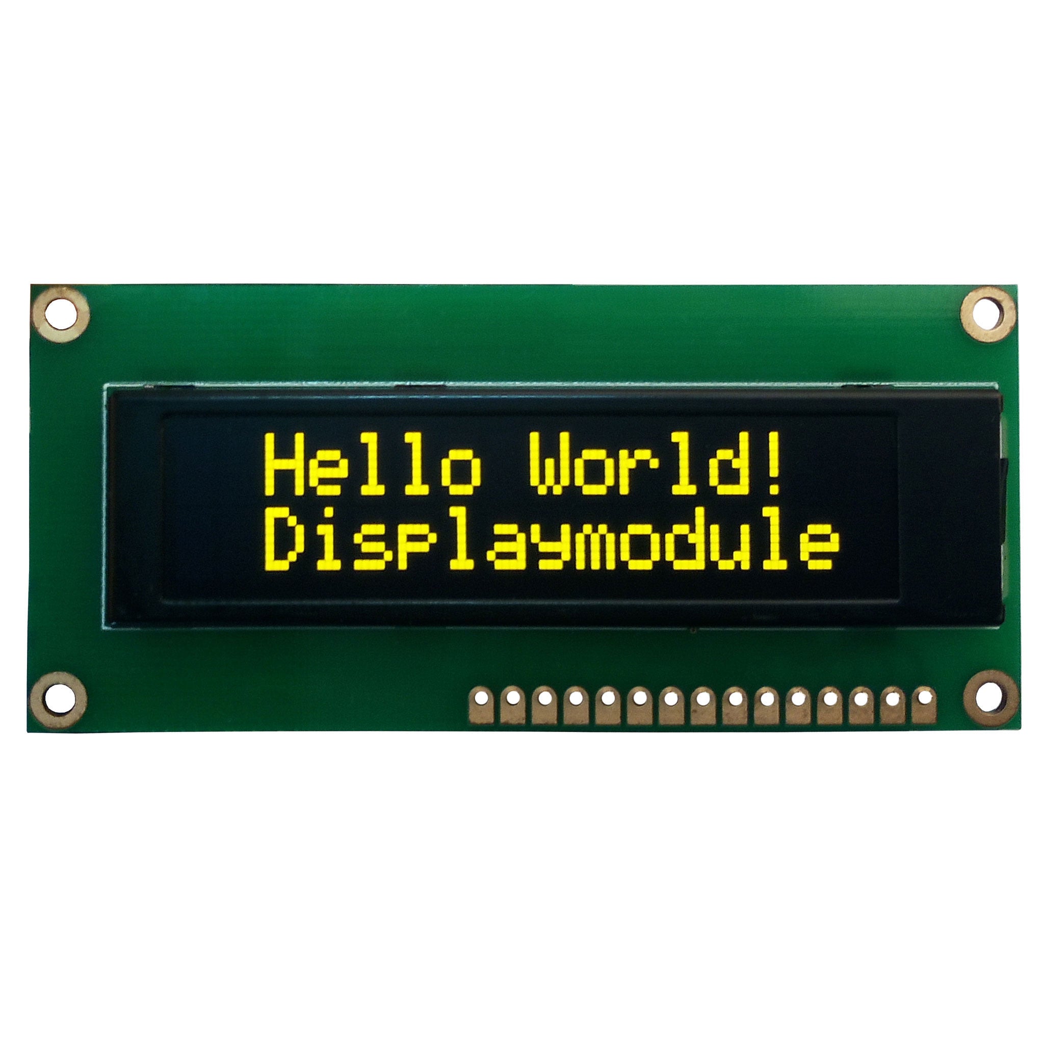
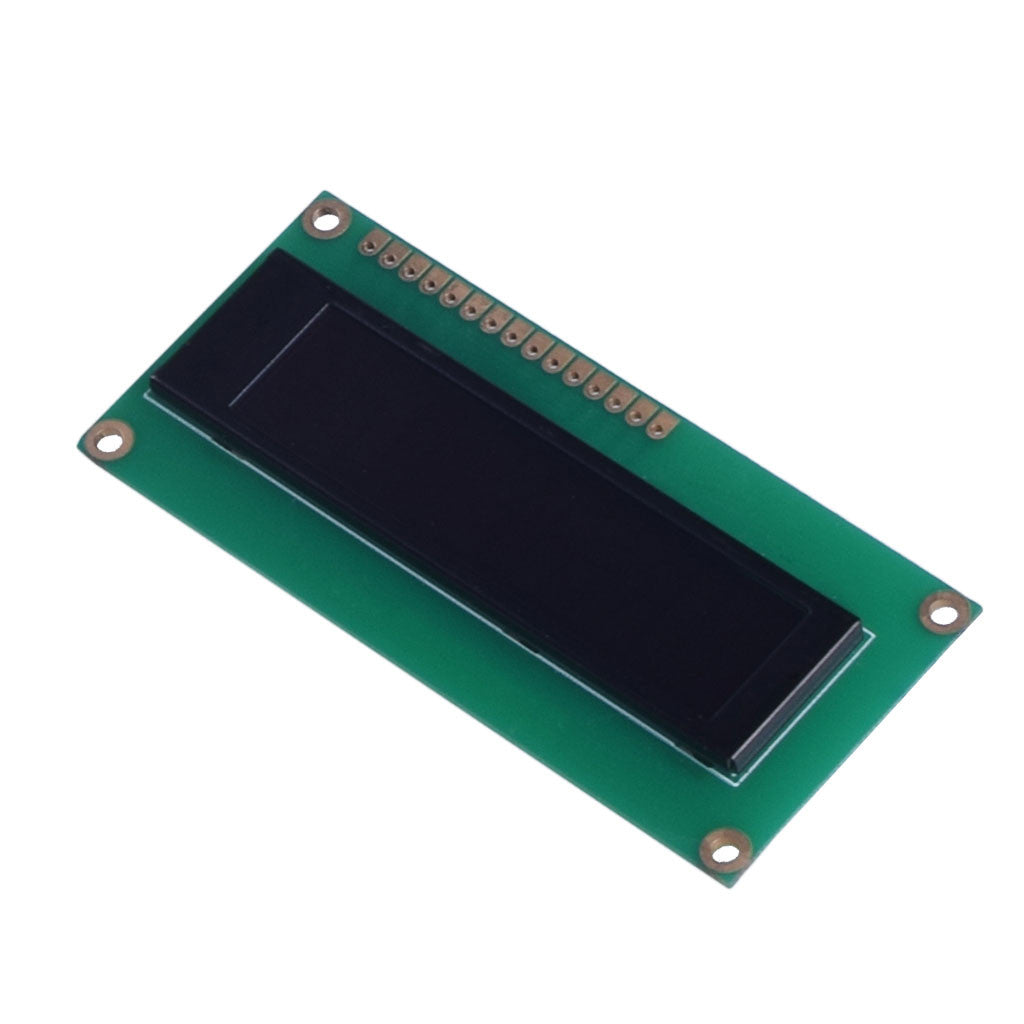
DM-OLED1602-601 is a 16-character × 2-line passive-matrix OLED display module with yellow characters and a US2066 controller. It supports 4-bit and 8-bit parallel, SPI, and I2C MPU interfaces for flexible integration with embedded systems.
The module operates at 1/16 duty. The main power specification is 3.3 V; the electrical characteristics list VDD at 3.0 V minimum, 3.3 V typical, and 5.5 V maximum, with VCC at 11 V minimum, 12 V typical, and 13 V maximum.

Technical Specifications
Key module, mechanical, electrical, optical, and environmental specifications for DM-OLED1602-601.
| Parameter | Specification |
|---|---|
| Product Model | DM-OLED1602-601 |
| Display Technology | Passive-matrix OLED |
| Character Format | 16 characters × 2 lines |
| Display Color | Yellow |
| Controller IC | US2066 |
| Duty | 1/16 |
| Host Interfaces | 4-bit or 8-bit 6800-series parallel, 4-bit or 8-bit 8080-series parallel, serial interface, or I2C |
| Main Feature Power Supply | 3.3 V |
| Logic Supply, VDD | 3.0 V min., 3.3 V typ., 5.5 V max. |
| Display Supply, VCC | 11 V min., 12 V typ., 13 V max. |
| Overall Outline | 80.00 ± 0.2 mm × 36.00 ± 0.2 mm |
| Viewing Area | 58.22 mm × 14.52 mm |
| Active Area | 56.22 mm × 11.52 mm |
| Dot Pitch | 0.60 mm × 0.70 mm |
| Weight | 15.5 g |
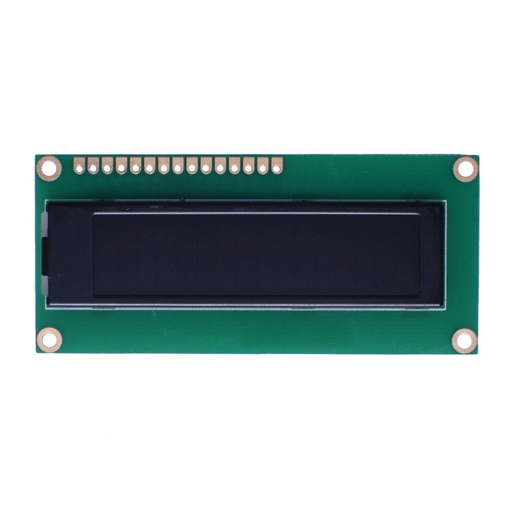
| Header Footprint | 15 through-holes, Ø1 mm, at 2.54 mm pitch |
| Mounting Holes | 4 × Ø2.50 mm |
| Operating Temperature | -40°C to +70°C |
| Storage Temperature | -40°C to +85°C |
| Viewing Angle | 80° typ. for top, bottom, left, and right |
| Response Time at 25°C | 20 µs typ. for Tr + Tf |
| Brightness | 120 cd/m² min., 150 cd/m² typ. |
| Contrast Ratio | 8,000:1 typ. |
| Lifetime | 50,000 hours min. |
US2066 Controller and Interface Selection
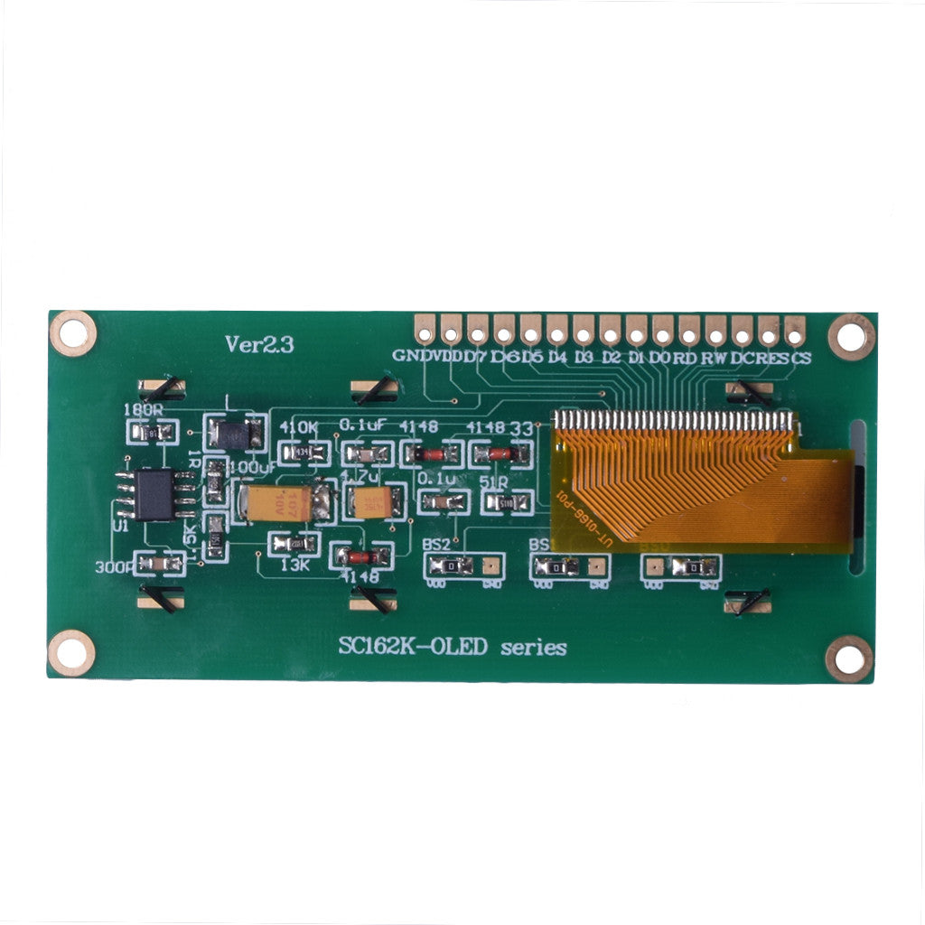
Interface mode is selected through BS2, BS1, and BS0. Six configurations are available: serial, I2C, 4-bit or 8-bit 6800 parallel, and 4-bit or 8-bit 8080 parallel.
For the 16×2 format, the module uses 1/16 duty. The US2066 supports ROM A, ROM B, and ROM C character sets, together with 5-dot and 6-dot font-width options.
000
Serial Interface
D0 is SCLK, D1 is serial data input, and the module pin summary identifies the serial data/control mapping.
010
I2C
D2 and D1 are used as SDAOUT and SDAIN, with D0 as SCL. The controller documentation requires pull-up resistors on SDA and SCL.
100
8-Bit 6800 Parallel
Uses D7-D0 with E, R/W, CS, D/C, and RES control signals.
101
4-Bit 6800 Parallel
Uses D7-D4 for data. The unused lower data lines are tied low according to the interface assignment.
110
8-Bit 8080 Parallel
Uses D7-D0 with RD, WR, CS, D/C, and RES control signals.
111
4-Bit 8080 Parallel
Uses D7-D4 with RD, WR, CS, D/C, and RES control signals.
15-Pin Module Interface
The 15-pin interface supports parallel, serial, and I2C operation. Signal functions change with the selected interface mode.
| Pin | Symbol and Function |
|---|---|
| 1 | VSS - Ground |
| 2 | VDD - 3.3 V power supply |
| 3-10 | D7-D0 - 8-bit bidirectional data bus. In serial mode, D1 is SDIN and D0 is SCLK. In I2C mode, D2 and D1 are used as SDAOUT and SDAIN, and D0 is SCL. |
| 11 | RD / E - Enable signal for 6800-series operation or read signal for 8080-series operation |
| 12 | RW / WR - Read/write control for 6800-series operation or write input for 8080-series operation; connect to VSS in serial mode |
| 13 | DC - Data/command control; functions as SA0 for I2C slave-address selection |
| 14 | RES - Reset input, active low |
| 15 | CS - Chip-select input, active low |
Mechanical Dimensions from the Product Drawing
Mechanical dimensions support PCB layout, enclosure design, display-window positioning, and mounting-hole placement.
Electrical and Optical Characteristics
Electrical, optical, temperature, and lifetime values for system design and component selection.
3.0 V minimum, 3.3 V typical, 5.5 V maximum.
11 V minimum, 12 V typical, 13 V maximum.
Power Sequence and Operating Limits
For 3.3 V I/O operation, hold RES low while the logic supply powers up. After stabilization, release reset, initialize the controller, apply VCC, wait for the specified delay, and turn the display on.
For power-down, turn the display off before removing VCC, then remove the logic supply.
Reset and Stabilization
Hold RES low during logic power-up, allow at least 3 μs for stabilization, then allow 100 μs after RES is set high.
Display Supply Timing
Apply VCC after controller setup and allow 100 ms before display-on. During power-down, switch the display off before removing VCC.
Absolute Maximum Limits
Operating temperature: -40°C to +70°C. Storage temperature: -40°C to +85°C.
Reliability Test Conditions
Module-level reliability test conditions include temperature, humidity, thermal shock, vibration, and static-electricity testing.
Download Engineering Resources
Download the product datasheet, US2066 controller documentation, library files, and interface initialization resources for development and integration.