








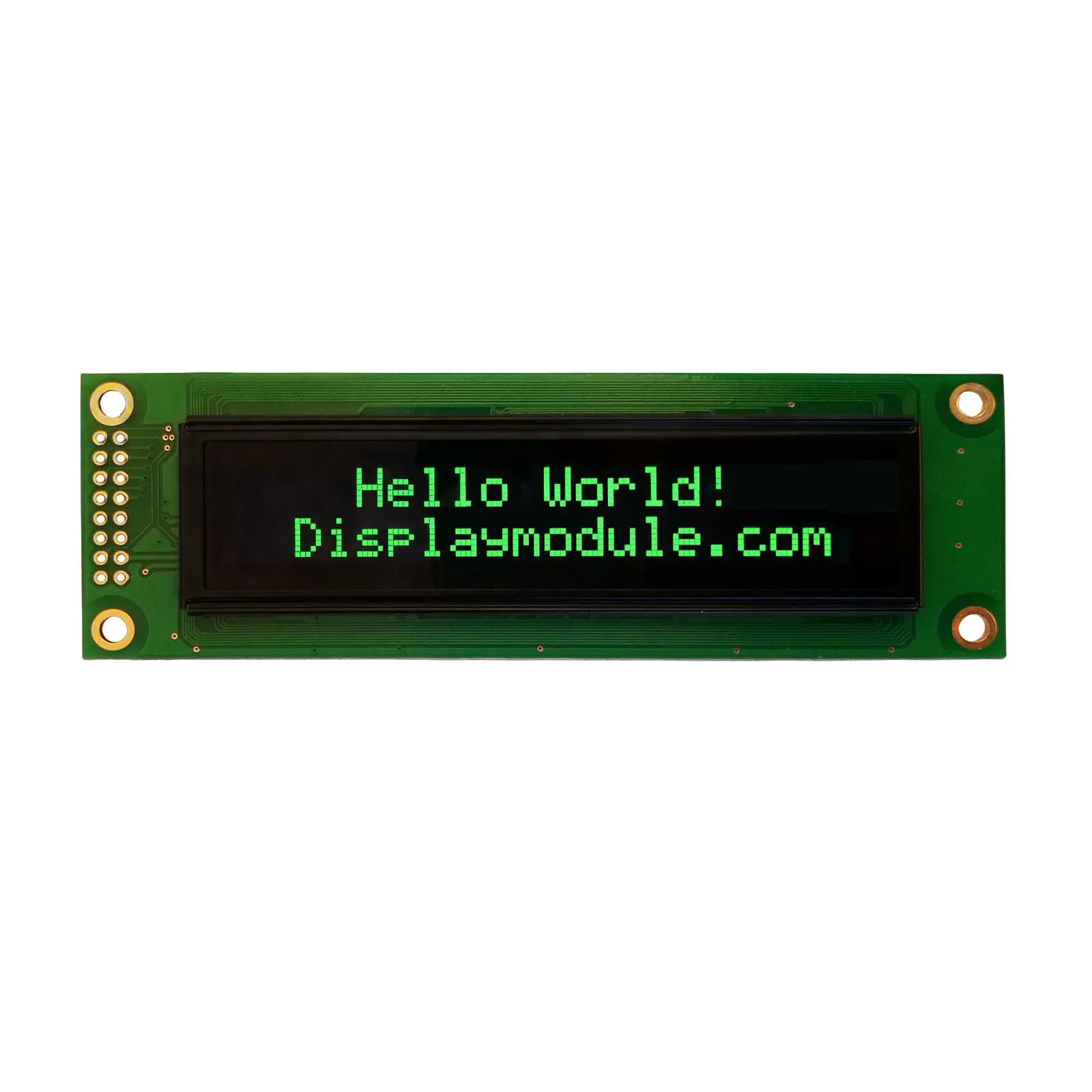
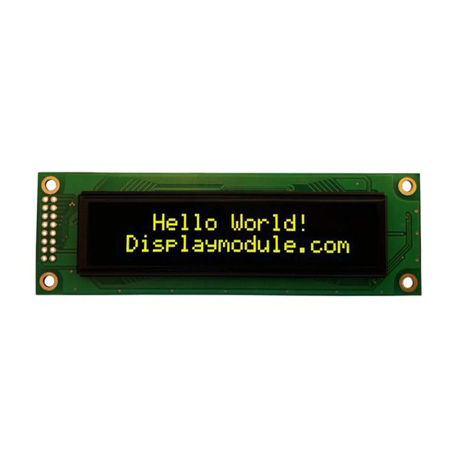
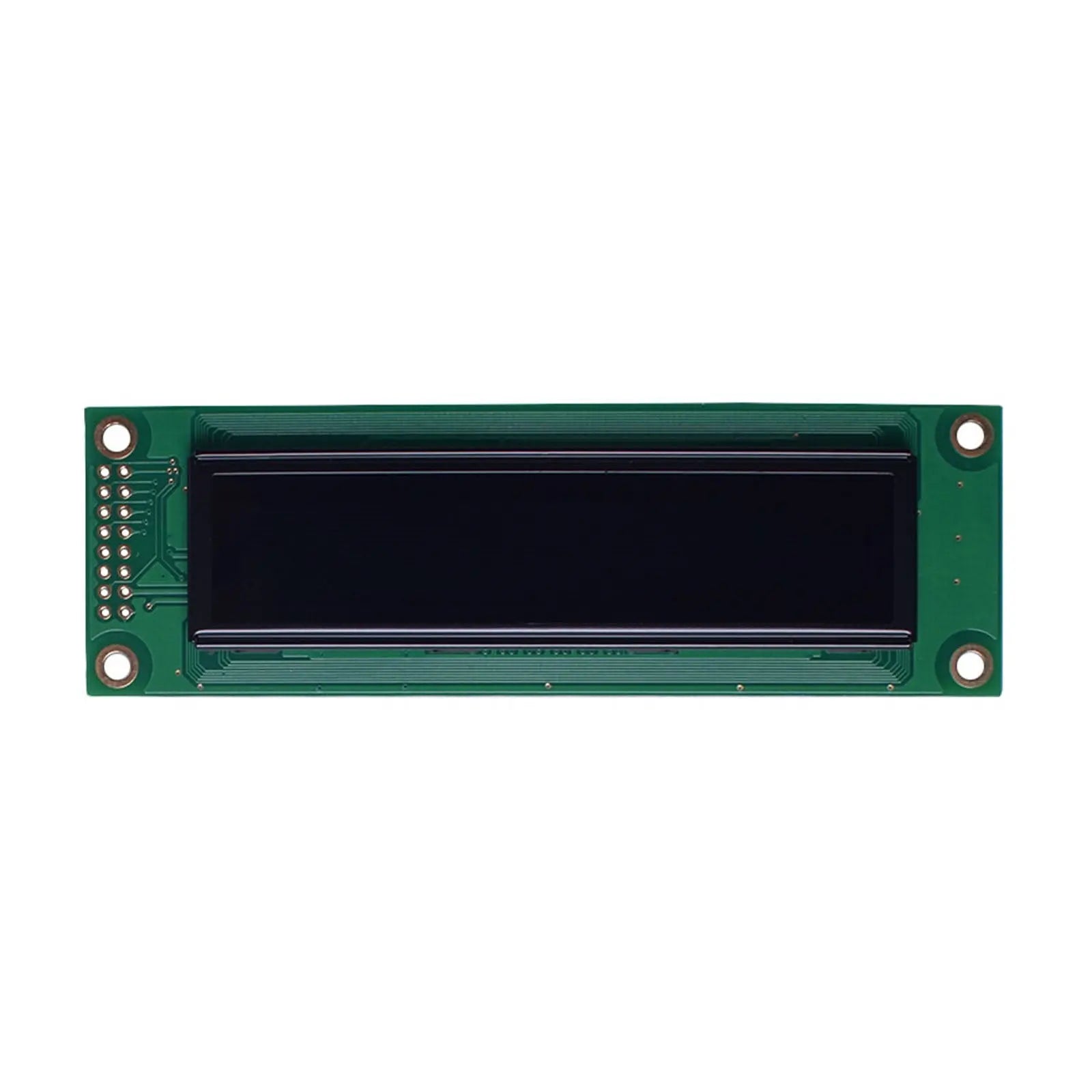
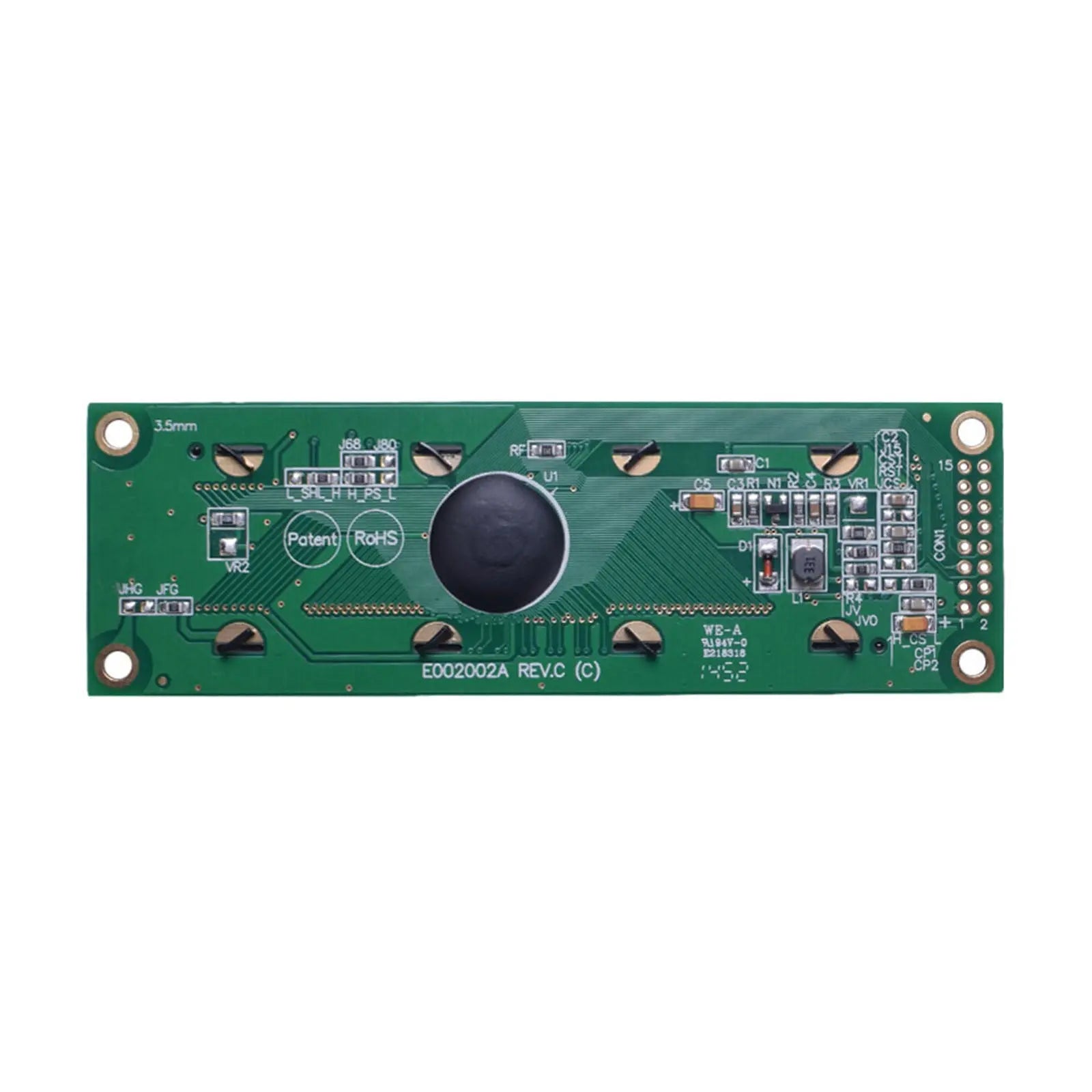
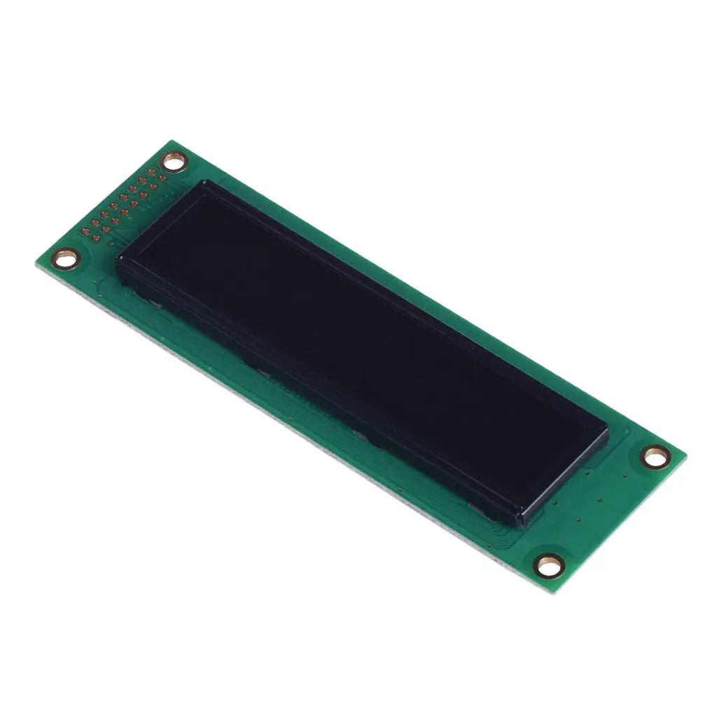
20x2 Character OLED Monochrome - MCU, SPI, I2C
- 💹 Enjoy a 20% discount for orders over 500
- 📉 A 15% discount is available for orders ranging from 200 to 499
- 🎁 A 10% discount is available for orders ranging from 50 to 199
- 🎁 A 5% discount is available when ordering 10-49
Interested in customizing this product? Get in touch with us.
Order samples, immediate delivery.
Factory bulk lead time: 3 weeks.
20x2 Character OLED Monochrome - MCU, SPI, I2C
- 💹 Enjoy a 20% discount for orders over 500
- 📉 A 15% discount is available for orders ranging from 200 to 499
- 🎁 A 10% discount is available for orders ranging from 50 to 199
- 🎁 A 5% discount is available when ordering 10-49
Resources & Downloads
20×2 Green Character OLED Module with WS0010 Controller
DM-OLED2002-608 is a passive-matrix character OLED module with 20 characters per line and two display lines. The product datasheet specifies green emission, a WS0010 controller, a 1/16 duty drive, and a parallel or serial MPU interface.
The product datasheet identifies the 6800-series parallel interface as the default jumper configuration. The documented alternatives are 8080-series parallel operation and a 3-line serial interface selected through the module jumper settings.

Verified Technical Specifications
The values below are taken from the DM-OLED2002-608 product datasheet and the supplied WS0010 controller specification. They support component selection, mechanical layout, interface review, and sample evaluation.
| Parameter | Verified Specification |
|---|---|
| Product Model | DM-OLED2002-608 |
| Display Type | Passive-matrix character OLED module |
| Display Format | 20 characters × 2 lines |
| Emitting Color | Green |
| Controller IC | WS0010 |
| Documented Interfaces | 6800-series parallel, 8080-series parallel, or 3-line serial MPU interface |
| Default Interface Setting | 6800-series parallel MPU interface |
| Parallel Data Width | 4-bit or 8-bit MPU data transfer |
| Supply Voltage | The product overview lists 3.0 V or 5.0 V operation. The electrical-characteristics table specifies VDD at 3.0 V min., 5.0 V typ., and 5.3 V max. Confirm the intended supply configuration and host logic levels before PCB design. |
| 50% Operation Current | 30 mA min., 33 mA typ., 40 mA max. |
| Module Outline | 116.0 ± 0.5 × 37.0 ± 0.5 mm, with 9.8 mm maximum depth |
| Viewing Area | 85.00 × 18.60 mm |
| Active Area | 77.30 × 11.85 mm |
| Drive Duty | 1/16 duty |
| Weight | 30.7 g |
| Viewing Angle | 160° min. horizontal and 160° min. vertical |
| Response Time | 20 µs typ. at 25°C |
| Contrast Ratio | 2000:1 min. |
| Brightness | 70 cd/m² min., 80 cd/m² typ. under the specified 50% checkerboard condition |
| Operating Lifetime | 80,000 hours min., 100,000 hours typ. under the datasheet lifetime definition |
| Operating Temperature | -40°C to +80°C absolute maximum range; project performance should be validated under the intended operating conditions |
| Storage Temperature | -40°C to +80°C absolute maximum range |
Optical Performance and Lifetime Reference
These optical values provide measurable reference points for readability, response, and lifetime planning during module qualification.
Interface Configuration and 16-Pin Assignment
Select the interface mode before final PCB and firmware design. The product datasheet identifies the 6800-series parallel setting as the default jumper configuration.
Available Interface Modes
Pin Functions by Mode
The supplied technical documents specify 6800 parallel, 8080 parallel, and a 3-line serial interface. Native I2C is not specified. The serial documentation should be reviewed directly before labeling the host connection as standard SPI.
WS0010 Controller Functions Relevant to Integration
The controller specification documents the interface, memory, font, and display-control functions used when developing firmware for the module.
MPU Communication
4-bit or 8-bit MPU communication, 6800-series or 8080-series parallel operation, and serial operation are documented. The controller specifies a 2 MHz high-speed MPU interface at VDD = 5 V.
Display Memory
The WS0010 includes 128 × 8-bit display RAM and 64 × 8-bit character-generator RAM for custom character patterns.
Character Fonts
Four selectable CGROM sets are documented: English/Japanese, Western European I, English/Russian, and Western European II. At controller level, WS0010 supports 5 × 8 and 5 × 10 dot fonts. The controller specification assigns the two-line, 1/16-duty configuration to the 5 × 8 dot font, while the 5 × 10 dot font is documented for a one-line, 1/11-duty configuration.
Display Control
Documented commands include display clear, cursor home, display on/off, cursor on/off, blinking, cursor shift, display shift, DDRAM access, and CGRAM access.
Mechanical Integration Reference
Use the official mechanical drawing for final enclosure, PCB, mounting-hole, and header-clearance decisions.
Reliability Test Conditions in the Product Datasheet
These conditions help engineering teams review environmental tolerance before sample evaluation and finished-product qualification.
Engineering Notes Before Ordering
Review the complete integration path
Confirm the module revision, electrical interface, jumper state, connector footprint, firmware initialization, and mechanical clearance before PCB release or volume procurement.
Potential Application Areas for Engineering Evaluation
The module can be evaluated for products that require a compact two-line character interface. Final electrical, mechanical, environmental, and regulatory suitability remains project-specific.
Industrial Equipment
Control panels, automation equipment, process displays, and monitoring interfaces that use concise text-based information.
Medical Instrument Interfaces
Text display evaluation for instruments and diagnostic equipment. Regulatory and system-level validation must be completed by the equipment manufacturer.
Appliances and Electronics
Audio equipment, appliances, and embedded devices that need two rows of readable character data.
Common Questions Before Sample Evaluation
Does DM-OLED2002-608 have a native I2C interface?
Native I2C is not listed in the supplied module or WS0010 documentation. The documented module options are 6800 parallel, 8080 parallel, and a 3-line serial interface. Confirm any adapter-based I2C requirement before ordering.
Is the documented serial interface standard SPI?
The product datasheet calls it a 3-line serial interface and assigns SCL, SDO, SDI, and /CS signals. Review the serial timing diagrams and host implementation before describing the connection as standard SPI.
Can the module operate with a 4-bit parallel bus?
Yes. The WS0010 and module documentation describe 4-bit and 8-bit MPU transfer. In 4-bit mode, DB4 through DB7 are used and each complete data transfer requires two 4-bit operations.
What does the stated OLED lifetime mean?
The product datasheet defines lifetime as the time at which luminance has decayed below 50% of its initial value. It lists 80,000 hours minimum and 100,000 hours typical and notes that screen-saving operation can extend OLED lifetime.
What should be checked before PCB layout?
Review the 16-pin footprint, module outline, viewing and active areas, four mounting positions, selected interface mode, jumper configuration, supply voltage, host logic levels, initialization sequence, and timing requirements.
Should the current production revision be reconfirmed?
Yes. Confirm the current module revision, available emitting color, interface configuration, sample status, and order requirements with DisplayModule before final design release or volume procurement.
Technical Resources
Download the available engineering resources for mechanical dimensions, pin assignments, electrical characteristics, interface timing, controller commands, character tables, initialization guidance, and Arduino development.