Connector planning
The 50-pin assignment groups the logic rails, interface-select pins, data bus, serial signals and LED connections. Match the FPC orientation to the mechanical drawing.


Popular Products
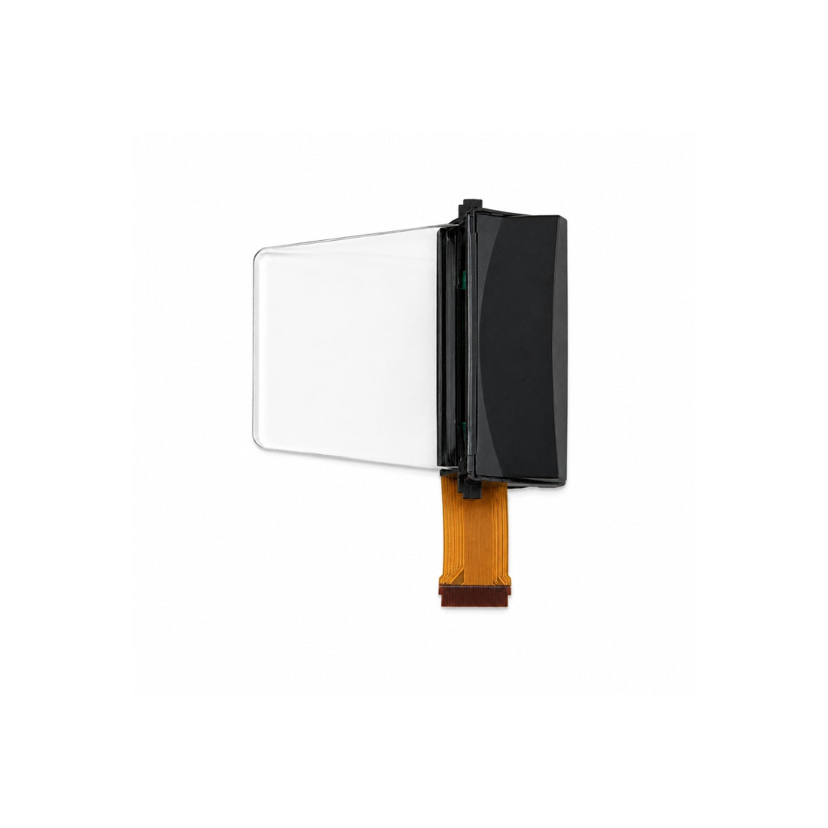
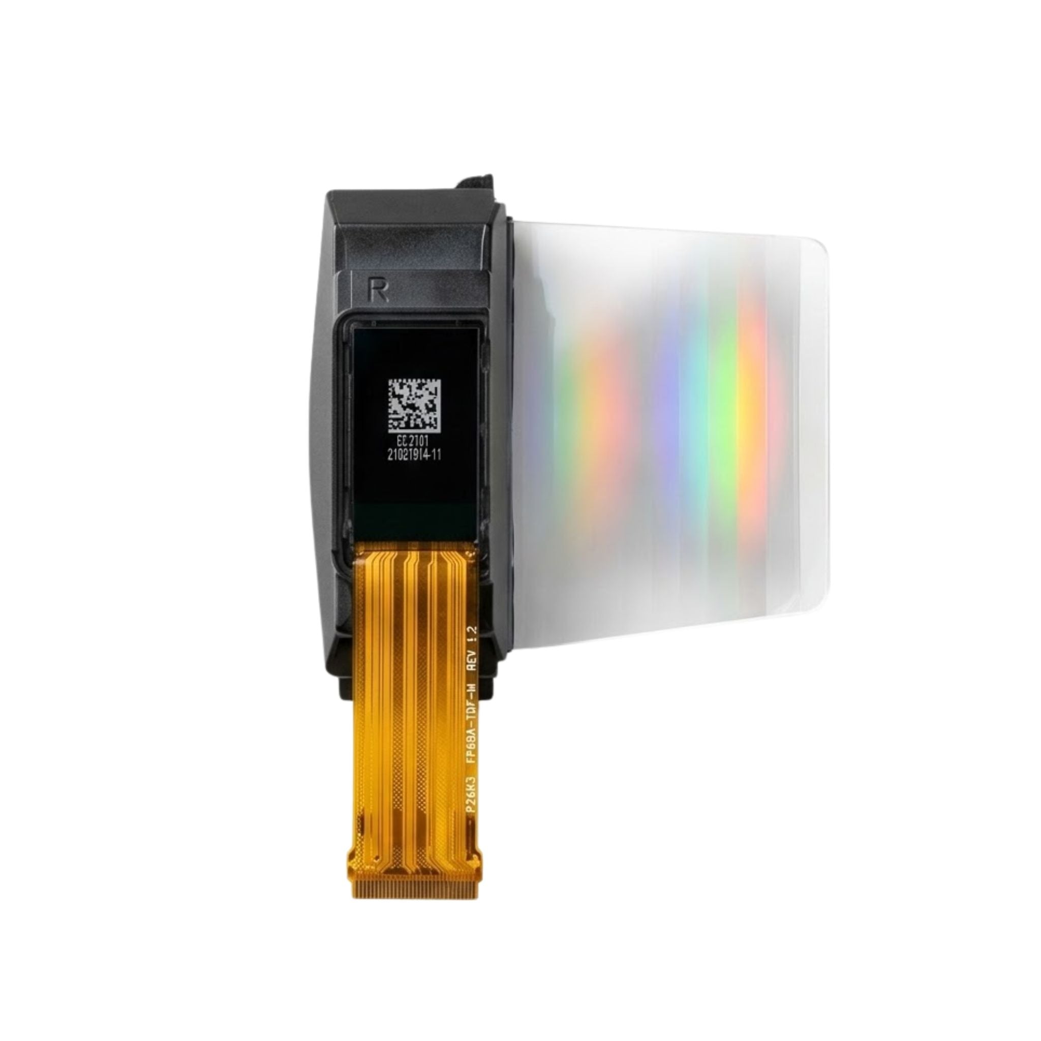


DM-TFT35-431
DM-TFT35-431 is a 3.5-inch portrait IPS display with a 320 × 480 pixel matrix and an ST7796S controller. Its 48.96 × 73.44 mm active area fits within a 54.58 × 83.57 × 2.18 mm module. The interface options include MCU parallel, 3- or 4-line SPI, and SPI control with a 16- or 18-bit RGB pixel bus.
 Click to enlarge
| Parameter | Specification |
|---|---|
| Product model | DM-TFT35-431 |
| Diagonal | 3.5 inch |
| Module dimensions | 54.58 × 83.57 × 2.18 mm |
| Active area | 48.96 × 73.44 mm |
| Display colors | 65K / 262K |
| Display mode | Transmissive; normally black |
| Viewing direction | All directions |
| Weight | 20 g |
| Operating temperature | −20 to +70 °C |
| Storage temperature | −30 to +80 °C |
The ST7796S supports multiple host interfaces. The chosen mode determines the interface-select states, connected signal set and transfer format; these should be reviewed together.
Provide the specified LED drive independently of the panel logic supply. Include both paths in the power budget.
Functional connection overview for DM-TFT35-431. Use the module pin assignment for the circuit and connector design.
Module outline · schematic view, not to scale
Use the dimensioned engineering drawing to position the cover opening and connection space. The illustration separates the image matrix from the physical module envelope.
Open the DM-TFT35-431 engineering drawing →The 320 × 480 portrait format can be evaluated for vertically arranged status information, menus or instrument graphics. This SKU is specified without integrated touch; plan any input device separately.
IM2 / IM1 / IM0: 000
Signals: DB17–DB0
IM2 / IM1 / IM0: 001
Signals: DB8–DB0
IM2 / IM1 / IM0: 010
Signals: DB15–DB0
IM2 / IM1 / IM0: 011
Signals: DB7–DB0
IM2 / IM1 / IM0: 101
Signals: SDA, SCL, CS; 9-bit serial data
IM2 / IM1 / IM0: 111
Signals: SDA, SCL, CS, RS; 8-bit serial data
The module also supports SPI + 16/18-bit RGB operation. For that path, use the RGB timing inputs VSYNC, HSYNC, PCLK and DE together with the controller configuration. Check the complete mode requirements in the module and ST7796S datasheets.
550 cd/m² minimum / 600 cd/m² typical
2.5 V min / 2.8 V typ / 3.3 V max
1.65 V min / 1.8 V typ / 3.3 V max
14 mA typical / 28 mA maximum
120 mA minimum / 160 mA typical
3.2 V typical
800:1 minimum / 1000:1 typical
30 ms typical / 40 ms maximum
70° minimum / 80° typical, each direction
The edge-lighting backlight uses eight white LED chips. The connector exposes LEDA and LEDK1–LEDK8; match the driver circuit to this backlight arrangement. Include the LED current separately from the panel electronics when calculating system power.
The 50-pin assignment groups the logic rails, interface-select pins, data bus, serial signals and LED connections. Match the FPC orientation to the mechanical drawing.
Apply the specified reset timing and initialize the selected controller mode before transferring the first frame. Use the module timing tables for MCU, SPI or RGB operation.
Allow for the full 54.58 × 83.57 mm outline and the FPC route. Base the visible opening on the dimensioned active area and the drawing’s aperture guidance.
No. IM2/IM1/IM0 select the interface, and the active data/control signals depend on that mode. The mode selector above lists the module’s MCU and serial assignments.
XR, YD, XL and YU are marked NC in this module’s pin table. Their names do not establish an integrated touch function for DM-TFT35-431.
Normal display current is 14 mA typical, while the LED specification lists 160 mA typical forward current and 3.2 V typical forward voltage. The connector exposes LEDA and LEDK1–LEDK8 for the eight-chip backlight. Logic rails are specified separately: VCI 2.5–3.3 V and IOVCC 1.65–3.3 V.
DisplayModule provides documentation and engineering assistance for display integration. For DM-TFT35-431, include your interface-select settings, logic voltage levels and backlight circuit when contacting the team.
Use technical support for wiring or documentation questions. Include the model number, connection details and a description of the behavior you observe.
Standard models are available for sample evaluation. For volume orders or proposed modifications, request a quote with your quantity and requirements. Confirm the model-specific MOQ, schedule and customization feasibility with the team.
About DisplayModule · Contact details and service information
Use the DM-TFT35-431 module datasheet for dimensions, connection details and product-specific electrical and optical limits. The controller documents provide the related interface and command reference.