









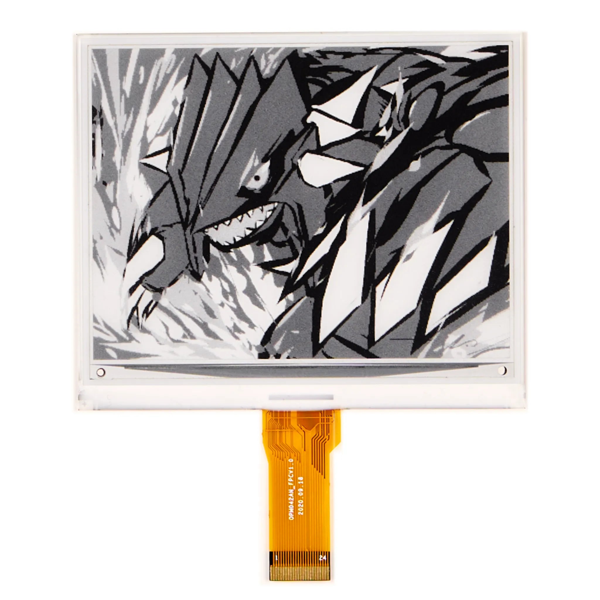
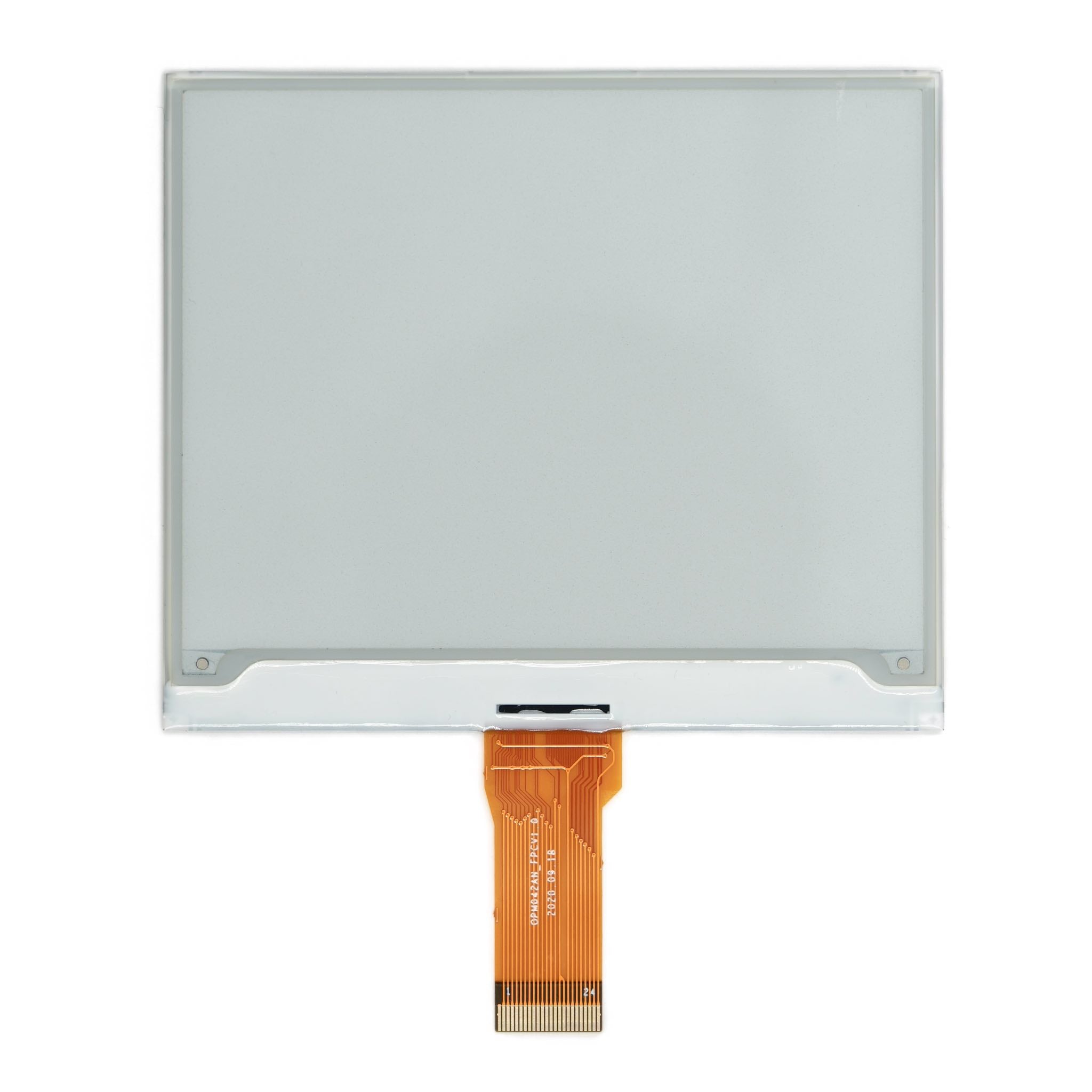
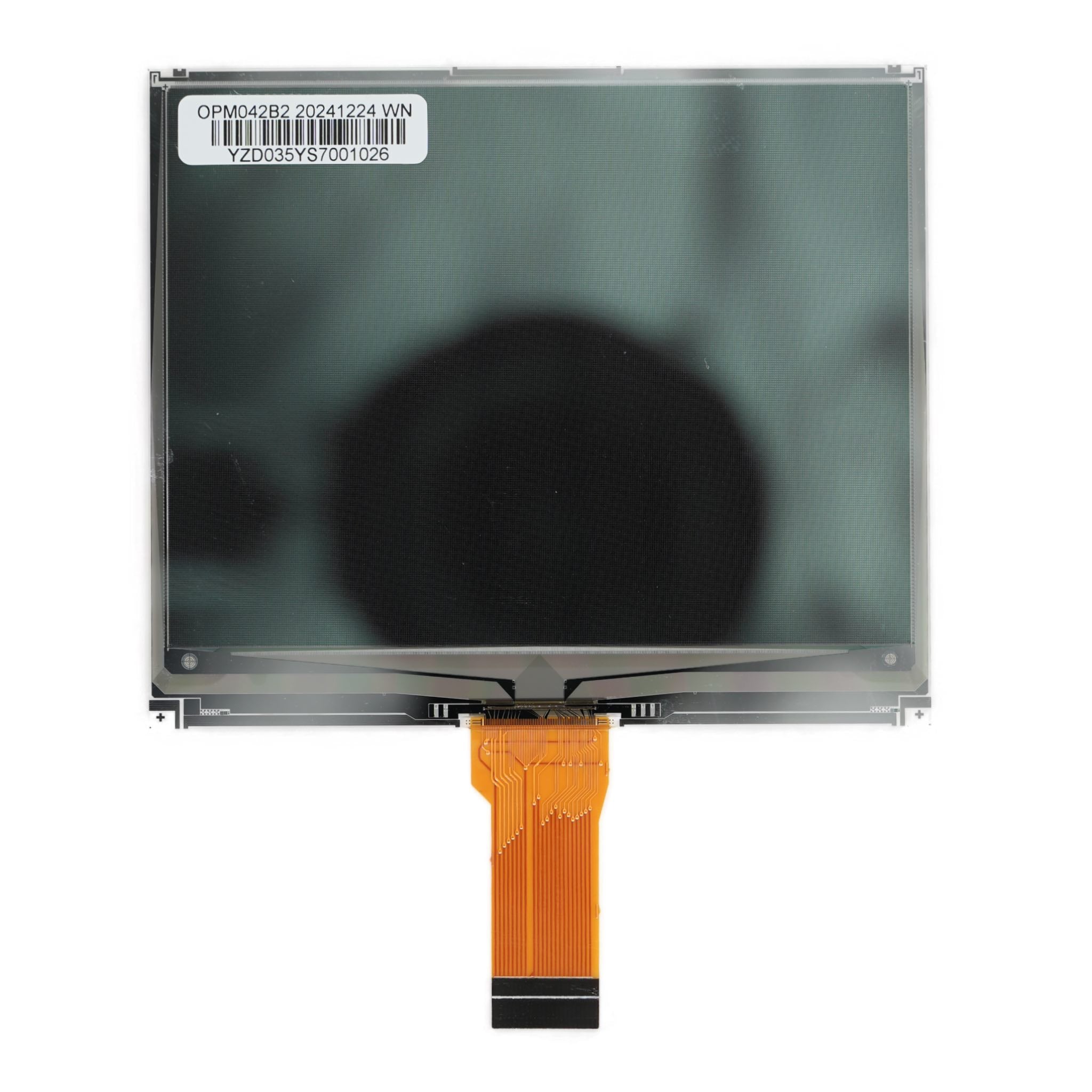
4.2" ePaper Display 400×300 - SPI I2C
- 💹 Enjoy a 20% discount for orders over 500
- 📉 A 15% discount is available for orders ranging from 200 to 499
- 🎁 A 10% discount is available for orders ranging from 50 to 199
- 🎁 A 5% discount is available when ordering 10-49
Interested in customizing this product? Get in touch with us.
Order samples, immediate delivery.
Factory bulk lead time: 3 weeks.
4.2" ePaper Display 400×300 - SPI I2C
- 💹 Enjoy a 20% discount for orders over 500
- 📉 A 15% discount is available for orders ranging from 200 to 499
- 🎁 A 10% discount is available for orders ranging from 50 to 199
- 🎁 A 5% discount is available when ordering 10-49
Resources & Downloads
4.2-inch 400×300 SPI ePaper Display Module
DMAYE04201LNA is a 4.2-inch active-matrix electrophoretic display with a 400×300 pixel matrix. The module supports pure reflective and bi-stable operation, on-chip display RAM, and hardware-selectable 4-wire or 3-wire SPI.
Integrated functions listed in the datasheet include gate and source buffers, an MCU interface, timing-control logic, an oscillator, DC-DC converter control, SRAM, LUT, and VCOM circuitry. TSCL and TSDA provide an I²C master interface for an external digital temperature sensor; display commands and image data are written through SPI.
Specification source: Technical values and interface definitions on this page are based on the DMAYE04201LNA Product Specification, version V1.0.0, dated July 1, 2025. Use the official datasheet and mechanical drawing for final design verification.

Datasheet Specifications
The following values are listed in the official DMAYE04201LNA datasheet. The document does not identify a separate controller IC model, mating connector part number, touch panel or touch controller, or quantified service-life value.
| Parameter | Specification |
|---|---|
| Product Model | DMAYE04201LNA |
| Display Technology | Active Matrix Electrophoretic Display (AM EPD), TFT-array driven |
| Screen Size | 4.2 inch |
| Resolution | 400 (H)×300 (V) pixels |
| Pixel Configuration | Square |
| Active Area | 84.80×63.60 mm |
| Pixel Pitch | 0.212×0.212 mm |
| Module Outline | 91.0 (H)×77.0 (V)×1.02 (D) mm |
| Weight | 15.0 g |
| Host Display Interface | Selectable 4-wire SPI or 3-wire 9-bit SPI through the BS pin |
| Temperature-Sensor Interface | I²C master interface on TSCL and TSDA for an external digital temperature sensor |
| Logic Supply Voltage | 2.4 V minimum, 3.0 V typical, 3.6 V maximum |
| Typical Panel Power | 45 mW typical, 240 mW maximum under the datasheet measurement condition |
| Typical Operating Current | 15 mA typical, 80 mA maximum at VDD = 3.0 V |
| Sleep Current | 35 µA typical, 50 µA maximum with RAM data retained |
| Deep-Sleep Current | 1 µA at VDD = 3.0 V with DC-DC off, no clock, no output load, and RAM data not retained |
| Operating Temperature | 0°C to 50°C |
| Storage Temperature | -25°C to 60°C |
| Operating Humidity | Up to 70% RH as specified |
| Storage Humidity | 30% RH to 60% RH as specified |
| Specified Operating Illuminance | Indoor only, 2000 lux |
| Published Application | Electronic Shelf Label system |
| Orientation | Landscape and portrait modes are listed as supported features |
Optical and Refresh Performance
The datasheet specifies panel-surface reflectivity and contrast values. Refresh values are listed at 25°C and require the waveform provided by OED.
Waveform Requirements
The listed electrical and optical characteristics are guaranteed only with the controller and waveform provided by OED. The datasheet states that full refresh flickers several times, while partial refresh does not flicker.
Use the module-specific waveform when evaluating the published refresh and optical values.
SPI, Temperature Sensor, and Pin Assignment
The display supports 4-wire SPI and 3-wire 9-bit SPI for host communication. Both modes are write-only. TSCL and TSDA are dedicated to an external digital temperature sensor and are not a host display-control interface.
Bus Selection Through BS
Select the bus mode through the BS pin. In both serial modes, only write operations are supported; do not send commands while BUSYN is high.
| Pin | Name and Function |
|---|---|
| 1 | NC. Do not connect with other NC pins. |
| 2 | GDR: N-channel MOSFET gate-drive control output. |
| 3 | RESE: current-sense input for the control loop. |
| 4 | NC. Do not connect with other NC pins. |
| 5 | VDHR: positive source-driving voltage capacitor node. |
| 6 | TSCL: I²C clock output to an external digital temperature sensor. |
| 7 | TSDA: I²C bidirectional data pin for an external digital temperature sensor. |
| 8 | BS: bus-interface selection input. |
| 9 | BUSYN: busy-state output. |
| 10 | RSTN: active-low reset input. |
| 11 | D/C: data/command input used in 4-wire SPI mode. |
| 12 | CSB: active-low MCU chip-select input. |
| 13 | SCL: SPI serial-clock input. |
| 14 | SDA: SPI serial-data input. |
| 15 | VDD: power supply for interface logic pins. |
| 16 | VDD: power supply for the chip. |
| 17 | VSS: ground. |
| 18 | VDDD: core-logic power pin. Connect a capacitor between VDDD and VSS under all circumstances. |
| 19 | VPP: power supply for OTP programming. |
| 20 | VSH: positive source-driving voltage 2 capacitor node. |
| 21 | VGH: positive gate-driving voltage capacitor node. |
| 22 | VSL: negative source-driving voltage capacitor node. |
| 23 | VGL: negative gate-driving voltage capacitor node. |
| 24 | VCOM: VCOM-driving voltage capacitor node. |
Electrical Levels and Serial Timing
Electrical operation must remain within the DC-characteristic limits rather than the absolute maximum ratings. The timing values below apply at VDD-VSS = 2.4 V to 3.3 V, 25°C, and a 20 pF load unless otherwise stated.
Logic and Power Conditions
SPI Timing Limits
Mechanical Integration
The mechanical drawing provides the module outline, active area, thickness, FPC location, contact details, and dimensional tolerances. Use the complete drawing when defining the enclosure opening and PCB connector position.
Connector note: The datasheet provides the 24-pin assignment and FPC geometry but does not specify a mating connector manufacturer or part number. Select a connector using the FPC dimensions and contact layout shown in the mechanical drawing.
Reference SPI Application Circuit
The module integrates the oscillator, booster and regulator control, SRAM, LUT, and VCOM functions. The published SPI reference circuit also includes external capacitors, diodes, resistors, an NMOS, and a 47 µH inductor.
Use the Published Component Network
The values below are reference component selections from the datasheet. Use the stated component type, rating, tolerance, and electrical limits.
Environmental Limits and Published Reliability Tests
The datasheet lists operating and storage limits together with ten environmental, electrostatic, and packaged-shipment tests. These are published test conditions; the document does not provide a quantified service-life value.
Use Conditions
Operation: 0°C to 50°C, up to 70% RH, with an indoor-only illuminance condition of 2000 lux.
Storage: -25°C to 60°C and 30% RH to 60% RH. The handling section recommends controlled warehouse storage at 15°C to 35°C, 30% RH to 60% RH, without sunlight or condensation.
Long exposure to high temperature, high humidity, sunlight, or fluorescent light may degrade panel performance. Protect the display surface from pressure, bending, twisting, moisture, scratching, and chemical cleaning agents.
High-temperature operation: 50°C, 30% RH, 240 hours; IEC 60068-2-2Bp.
Low-temperature operation: 0°C, 240 hours; IEC 60068-2-2Ab.
High-temperature storage: 70°C, 23% RH, 240 hours; IEC 60068-2-2Bp.
Low-temperature storage: -25°C, 240 hours; IEC 60068-2-1Ab.
High-temperature, high-humidity operation: 40°C, 90% RH, 168 hours; IEC 60068-2-3CA.
High-temperature, high-humidity storage: 60°C, 80% RH, 240 hours; IEC 60068-2-3CA.
Thermal shock: -25°C for 30 minutes → 70°C for 30 minutes, 100 cycles; IEC 60068-2-14.
Package vibration: 1.04 G, 10-500 Hz, X/Y/Z, one hour in each direction, fully packed for shipment.
Package drop: 122 cm onto concrete, one corner, three edges, and six faces, fully packed for shipment.
Non-operating electrostatic test: machine model ±250 V, 0 Ω, 200 pF; IEC 62179 and IEC 62180.
Integration Checklist
Review these datasheet-controlled items before PCB layout, enclosure design, firmware integration, or sample evaluation.
Documentation and Selection
Use the DMAYE04201LNA datasheet and mechanical drawing for dimensions, pin assignment, electrical limits, timing, optical performance, and the reference application circuit.
Confirm any requirement that is not quantified in the datasheet before product selection.
Interface: Select 4-wire or 3-wire SPI through the BS pin and account for host voltage levels, BUSYN handling, and write-only serial communication.
Waveform and LUT: Use the waveform specified for the module when targeting the published full-refresh and partial-refresh performance.
Temperature sensing: TSCL and TSDA connect to an external digital temperature sensor. The datasheet does not specify a sensor part number.
Mechanical fit: Use the complete drawing for dimensions, tolerances, FPC orientation, housing opening, and connector position.
Application environment: Keep operation and storage within the documented temperature, humidity, indoor illuminance, condensation, and light-exposure limits.
Compliance: The certification table marks RoHS with a check. CE, FCC, and Other are marked with crosses.
Common Questions Before Ordering
Can the display be controlled through I²C?
No host-display I²C mode is specified. Display commands and image data use 4-wire SPI or 3-wire 9-bit SPI. TSCL and TSDA provide the I²C master interface for an external digital temperature sensor.
Does the module retain an image without continuous refresh power?
The datasheet identifies the display as bi-stable. Power is required for communication and image updates; the datasheet does not provide a separate image-retention duration.
Is partial refresh supported?
Yes. The datasheet lists a typical partial-refresh time of 250 ms at 25°C and requires the waveform provided by OED.
Is the module intended for outdoor sunlight exposure?
The datasheet specifies indoor-only operation at up to 2000 lux and warns that prolonged sunlight or fluorescent-light exposure may degrade panel performance. It does not identify the module as outdoor-rated.
Are external drive components required?
Yes. The reference SPI circuit includes capacitors, three diodes, two specified resistors, an NMOS, and a 47 µH inductor. Use the published circuit and component-selection table.
Is a touch panel included?
No touch panel or touch-controller specification is provided in the datasheet.
Download Official Datasheet
Use the official DMAYE04201LNA datasheet to verify dimensions, pin assignment, SPI modes, electrical limits, optical values, reliability test conditions, and the reference application circuit.