









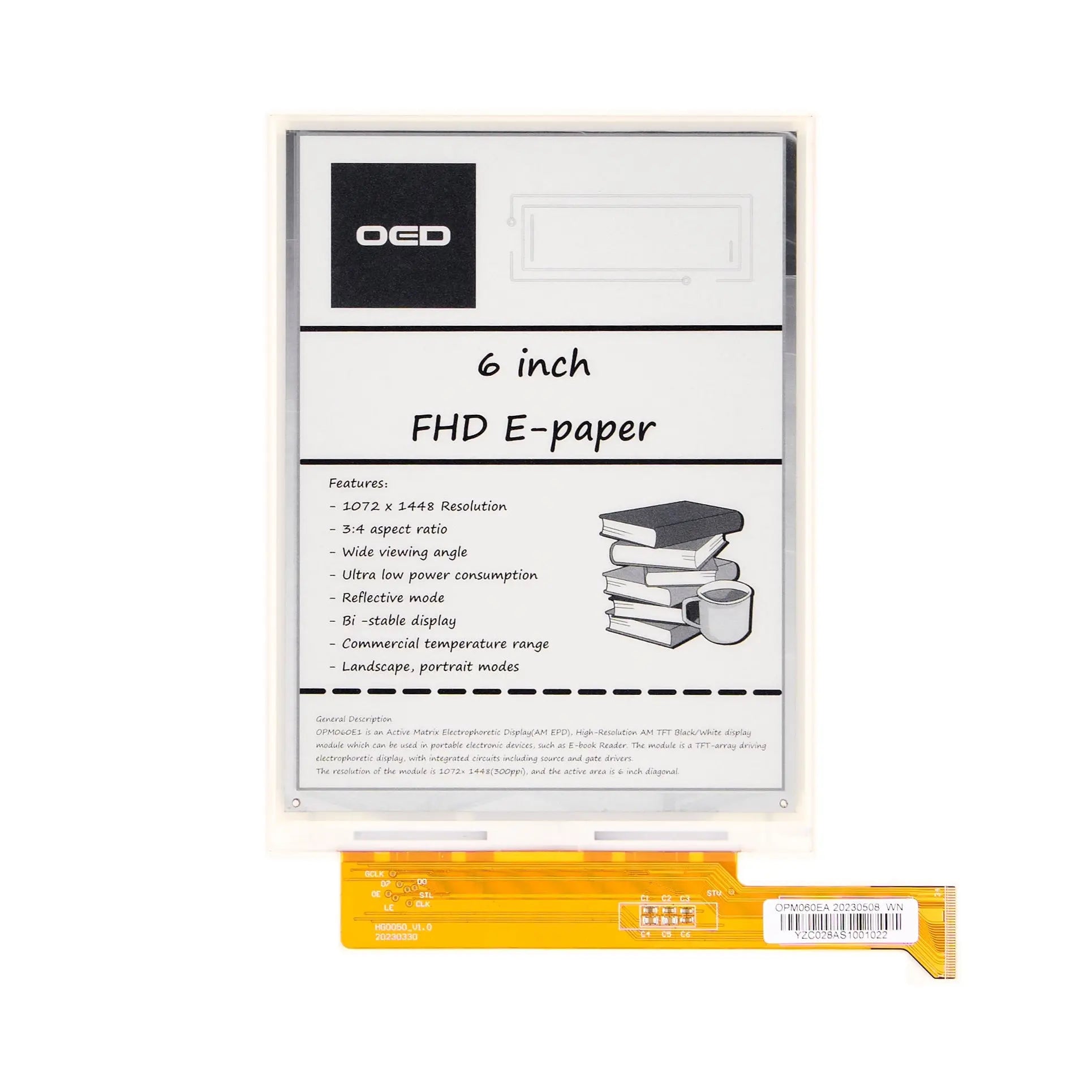
6.0" ePaper 1072x1448 - MCU
- 💹 Enjoy a 20% discount for orders over 500
- 📉 A 15% discount is available for orders ranging from 200 to 499
- 🎁 A 10% discount is available for orders ranging from 50 to 199
- 🎁 A 5% discount is available when ordering 10-49
Interested in customizing this product? Get in touch with us.
Order samples, immediate delivery.
Factory bulk lead time: 3 weeks.
6.0" ePaper 1072x1448 - MCU
- 💹 Enjoy a 20% discount for orders over 500
- 📉 A 15% discount is available for orders ranging from 200 to 499
- 🎁 A 10% discount is available for orders ranging from 50 to 199
- 🎁 A 5% discount is available when ordering 10-49
Resources & Downloads
6.0-Inch 1072 × 1448 Black/White ePaper Display - MCU
DMAYE0600X7NA is a 6.0-inch active matrix electrophoretic display with a 1072 × 1448 pixel matrix, 300 PPI density and an MCU parallel interface. The module uses a high-resolution AM TFT black/white structure with integrated source and gate drivers.
The datasheet identifies reflective operation, bi-stable display behavior, wide viewing angle, portrait and landscape orientation, and a commercial operating temperature range. It also lists portable electronic devices such as e-book readers as an example application.
Document reference: Product specification V1.0.0, dated March 8, 2025. Review the current datasheet and mechanical drawing together before PCB, enclosure or connector release.

Verified Technical Specifications
The values below are based on the supplied product specification and mechanical drawing. Values marked as TBD in the datasheet are not converted into estimated or guaranteed figures.
| Parameter | Specification |
|---|---|
| Model / SKU | DMAYE0600X7NA |
| Datasheet Version | V1.0.0, dated March 8, 2025 |
| Display Technology | Active Matrix Electrophoretic Display (AM EPD) |
| Display Structure | High-resolution AM TFT black/white display module with integrated source and gate drivers |
| Screen Size | 6.0 inches diagonal |
| Active Area | 90.584 mm (H) × 122.356 mm (V) |
| Resolution | 1072 (H) × 1448 (V) pixels |
| Pixel Configuration | Rectangular pixels |
| Pixel Pitch | 84.5 µm (H) × 84.5 µm (V) |
| Pixel Density | 300 PPI |
| Aspect Ratio | 3:4 |
| Display Mode | Reflective |
| Image Retention Type | Bi-stable electrophoretic display |
| Supported Orientation | Landscape and portrait modes |
| Interface | MCU parallel interface |
| Data Bus | 8-bit source-driver data bus through D0 to D7 |
| FPC Connection | 34-pin connection shown in the mechanical drawing and pin-definition table |
| Module Dimensions | 101.8 mm (H) × 138.4 mm (V) × 0.82 mm (D) |
| Weight | 24 g |
| Logic Supply Voltage | VDD: 3.0 V minimum, 3.3 V typical, 3.6 V maximum |
| Logic Supply Current | IVDD: 2.0 mA typical at VDD = 3.3 V. This value is not the total module update power. |
| Gate Positive Supply | VGH: 24 V minimum, 25 V typical, 26 V maximum |
| Gate Positive Supply Current | IVGH: 0.6 mA typical at VGH = 25 V |
| Gate Negative Supply | VGL: -21 V minimum, -20 V typical, -19 V maximum |
| Gate Negative Supply Current | IVGL: -3.0 mA typical at VGL = -20 V |
| Source Positive Supply | VPOS: 14.6 V minimum, 15 V typical, 15.4 V maximum |
| Source Negative Supply | VNEG: -15.4 V minimum, -15 V typical, -14.6 V maximum |
| Source Supply Asymmetry | VASYM, defined as VPOS + VNEG: -800 mV minimum to +800 mV maximum |
| Common Voltage | VCOM is adjustable within the datasheet range of -2.5 V to -0.9 V |
| Source and Common Supply Currents | IPOS, INEG and ICOM are listed as TBD in the supplied datasheet |
| Standby Module Power | TBD in the supplied datasheet |
| Typical Module Power | TBD in the supplied datasheet |
| Typical Image Update Time | 450 ms at 25°C |
| White Reflectivity | 42% minimum and 45% typical under the datasheet measurement conditions |
| Contrast Ratio | 10:1 minimum and 15:1 typical under the datasheet measurement conditions |
| Operating Temperature | 0°C to +50°C |
| Operating Relative Humidity | 0% to 70% RH |
| Storage Temperature | -20°C to +70°C |
| Storage Relative Humidity | 30% to 60% RH |
| Material Compliance | RoHS is marked as supported in the supplied datasheet. The mechanical drawing also states that the material conforms to the RoHS standard. |
| CE and FCC Status | CE and FCC are marked as not supported in the supplied product specification |
| Controller IC | No separate controller IC model is identified. The datasheet states that source and gate drivers are integrated. |
| Touch Configuration | No touch panel or touch-controller specification is provided. Confirm any separate touch requirement before ordering. |
Interface and 34-Pin Signal Structure
The module uses separate source-driver, gate-driver and power connections. Review the complete pin table before selecting a mating connector or releasing the host PCB.
Panel-Level MCU Interface
The datasheet defines an 8-bit data path, dedicated source and gate timing signals, several high-voltage display rails and a border connection.
No mating connector part number is specified. Confirm connector compatibility, FPC orientation and contact alignment before PCB release.
Power Sequence and Interface Timing
The datasheet states that the specified power-on and power-off sequence must be followed to prevent latch-up damage.
Power-On Sequence
Power-Off Sequence
The 200 kHz value applies specifically to the CPV gate shift clock. It should not be presented as a general maximum clock rate for the complete MCU interface.
Optical and Environmental Conditions
Optical results are defined under the measurement setup stated in the official specification rather than as unconditional values for every enclosure or lighting environment.
White Reflectivity
42%-45%42% minimum and 45% typical.
Contrast Ratio
10:1-15:110:1 minimum and 15:1 typical.
Measurement Setup
25°Cfv = 85 Hz, Eye-One Pro spectrophotometer, 45-degree illumination and perpendicular detection.
Reliability Conditions Listed in the Datasheet
These are documented evaluation conditions for the module and its shipment packaging. They should not be described as separate product certifications or as guarantees for the customer’s finished device.
Temperature Operation
High temperature: +50°C, 30% RH for 240 hours.
Low temperature: 0°C for 240 hours.
Temperature Storage
High temperature: +70°C, 23% RH for 240 hours.
Low temperature test: -25°C for 24 hours.
Humidity Conditions
Operation: +40°C, 90% RH for 240 hours.
Storage: +60°C, 80% RH for 240 hours.
Thermal Shock
One cycle consists of -25°C for 30 minutes followed by +70°C for 30 minutes.
The datasheet lists 100 cycles.
Shipment Package Tests
Vibration: 1.04 G, 10-500 Hz, X/Y/Z directions, one hour per direction.
Drop: 122 cm onto concrete, covering one corner, three edges and six faces.
Non-Operating and Surface Tests
Electrostatic effect: machine model, ±250 V, 0 Ω, 200 pF.
Stylus tapping: polyacetal pen, R0.8 mm tip, 200 gf, 30 times per minute, 13,500 total taps.
The reliability table lists a -25°C low-temperature storage test condition, while the general storage range is stated as -20°C to +70°C. Both values are retained in their separate datasheet contexts.
Engineering Review Before Ordering
Use these checks to confirm that the panel, power architecture, timing and mechanical connection fit the intended system.
Power architecture: Confirm generation and sequencing of VDD, VGL, VGH, VPOS, VNEG and VCOM.
Interface timing: Validate D0-D7, CLK, LE, OE, SPH, CPV, STV and MODE1 against the complete timing diagrams.
Mechanical fit: Review the 101.8 × 138.4 mm outline, 0.82 mm thickness, active area and FPC clearance.
Total power: Do not use the 2.0 mA IVDD value as the complete panel update-current figure.
Touch requirement: Treat touch as unconfirmed unless a separate touch drawing and controller specification are supplied.
Compliance: Review the available RoHS evidence and do not assume CE or FCC coverage for this module.
Common Questions Before Ordering
Answers below are limited to information supported by the supplied product page, datasheet and mechanical drawing.
Is this a black-and-white ePaper display?
Yes. The general description identifies DMAYE0600X7NA as a high-resolution AM TFT black/white electrophoretic display module.
Does the module include a touch panel?
No touch panel, touch-controller IC or touch-interface specification is provided. Confirm any separate touch requirement before ordering.
Does 2.0 mA represent the total display power?
No. The 2.0 mA value is the typical IVDD logic-supply current at VDD = 3.3 V. The datasheet lists typical and standby module power as TBD.
What does the 450 ms update time mean?
It is the typical image update time stated at 25°C. Actual system behavior may also depend on the driving waveform, power circuit and host implementation.
Is a controller or driver board included?
The supplied specification describes the display module, integrated source and gate drivers, panel-level power rails and MCU signals. It does not confirm that an external controller board or power board is included. Confirm the order scope before purchase.
Is the module CE or FCC certified?
The datasheet marks RoHS as supported and marks CE and FCC as not supported. Do not treat the finished customer product as certified based only on the module datasheet.
Is firmware or example code available?
The supplied datasheet refers to a GitHub link but does not provide a verified downloadable URL in the material used for this page. Confirm current firmware or example-code availability before ordering.
Can I request samples or customization?
Confirm current sample availability, lead time, supported modifications, documentation and order scope directly with DisplayModule before purchase.
Download Official Datasheet
Review the official file for the complete electrical tables, 34-pin definitions, power sequencing, timing diagrams, optical conditions, reliability conditions and mechanical dimensions.
Use the current datasheet and approved mechanical drawing as the primary references before sample approval, PCB layout or enclosure release.