







내용으로 건너뛰기

장바구니

장바구니가 비어있습니다

쇼핑 계속하기

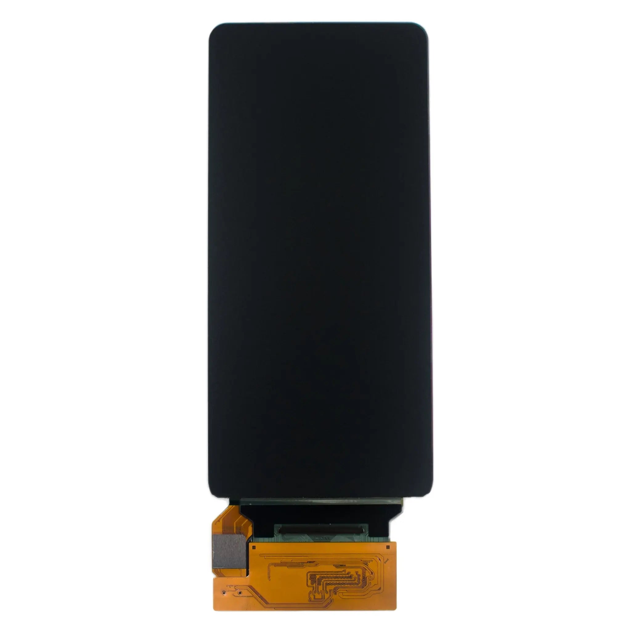
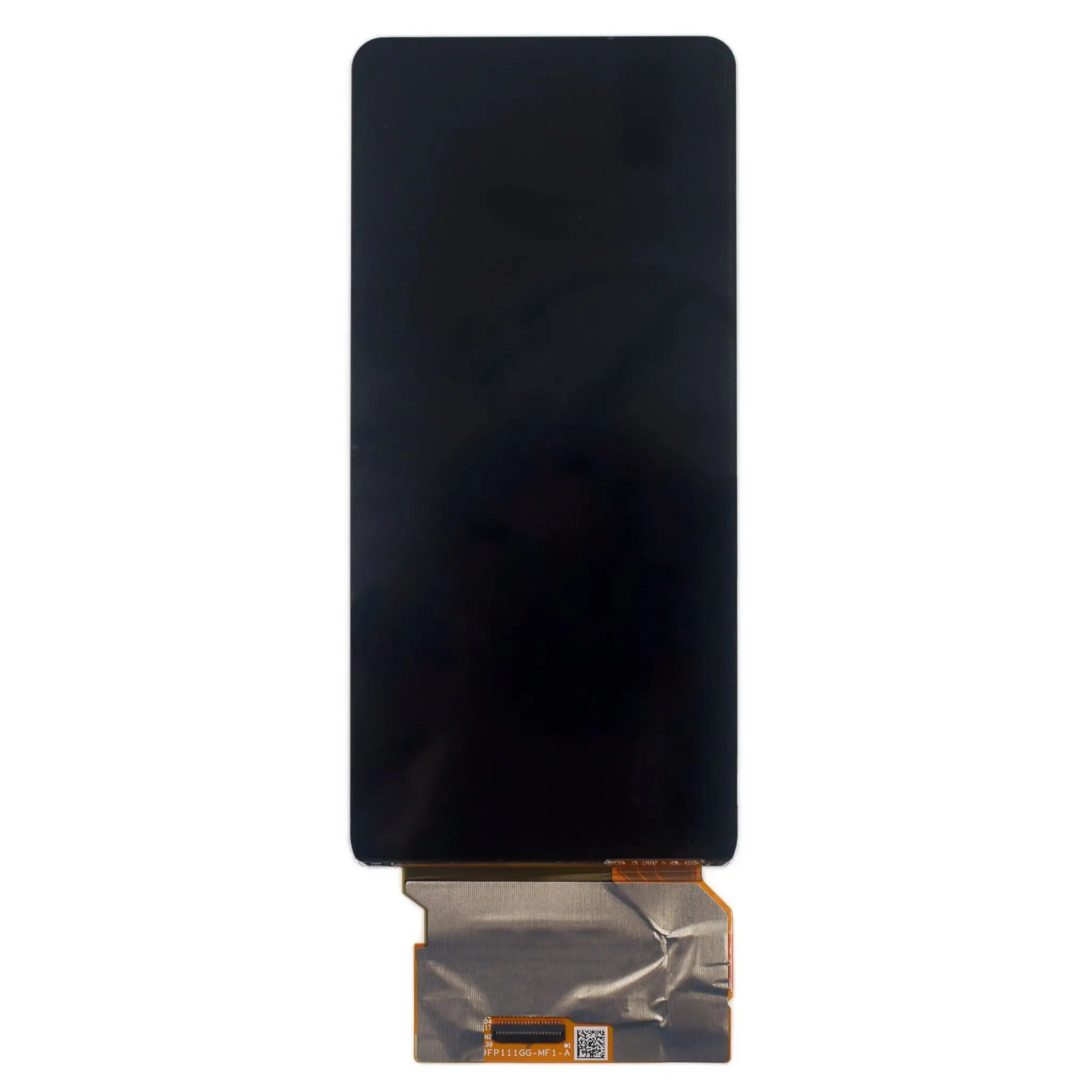
6.39" AMOLED Display 1080×2340 High-Resolution Screen – MIPI Interface

SKU: DMKDO06401CCA
할인 가격$99.00
  • 💹 Enjoy a 20% discount for orders over 500
  • 📉 A 15% discount is available for orders ranging from 200 to 499
  • 🎁 A 10% discount is available for orders ranging from 50 to 199
  • 🎁 A 5% discount is available when ordering 10-49

Interested in customizing this product? Get in touch with us.

Order samples, immediate delivery.

Factory bulk lead time: 3 weeks.


공유
6.39" AMOLED Display 1080×2340 High-Resolution Screen – MIPI Interface DisplayModule
6.39" AMOLED Display 1080×2340 High-Resolution Screen – MIPI Interface 할인 가격$99.00

Resources & Downloads

SKU: DMKDO06401CCA

6.39-Inch AMOLED Display Module — 1080 × 2340, 4-Lane MIPI

Color active-matrix AMOLED module using Low Temperature Poly-silicon Thin Film Transistors as active switching devices. The display has a 6.39-inch diagonal active area, a 1080 × 2340 pixel array and support for 16.7 million colors.

The product specification identifies an SD5207 display controller, an FT3519 on-cell touch controller and a 4-lane MIPI display interface.

The values below are based on product specification V1.0.0 dated July 1, 2025. TBD, incomplete and internally inconsistent source entries are identified instead of being estimated.

DMKDO06401CCA 6.39-inch AMOLED display module mechanical outline

1080 × 2340

Pixel array

500 cd/m² Typical

450 cd/m² minimum

69.84 × 150.42 mm

Module width × height

9 g

Specified module weight

Technical Specifications

Parameter Specification
Display Mode AMOLED
Driver Element TFT active matrix using LTPS switching devices
Diagonal Size 6.39 inches
Active Area 68.04 × 147.42 mm
Pixel Array 1080 × 2340 pixels
Pixel Pitch 0.063 × 0.063 mm
Display Colors 16.7 million colors
Subpixel Description The source describes red and green dots or blue and green dots, with two pixels sharing red or blue dots in a vertical stripe arrangement.
Viewing Direction All o'clock
Display Controller SD5207
Touch Controller FT3519 on-cell
Display Interface 4-lane MIPI
Module Dimensions 69.84 × 150.42 × 0.798 mm
Weight 9 g
Operating Temperature −20°C to +70°C
Storage Temperature −40°C to +80°C

Optical Performance Data

500 cd/m²

Typical white-mode luminance

450 cd/m²

Specified minimum luminance

30,000 Hours Listed

The table does not state the luminance endpoint, image pattern, duty cycle or test temperature.

All O'Clock

Viewing direction listed in the specification

Typical CIE 1931 Coordinates

Color Typical x / y
White 0.297 / 0.327
Red 0.673 / 0.326
Green 0.227 / 0.684
Blue 0.139 / 0.045

Contrast Ratio

TBD in the source specification. No numeric contrast value is claimed here.

NTSC Color Gamut

TBD in the source specification. No NTSC percentage is claimed here.

Response Time

The datasheet includes a response-time definition but does not provide a numeric value.

Optical Measurement Conditions

Dark room, 25 ± 2°C ambient temperature and 15-minute warm-up. The source names FPM520 equipment, SR-3 for chromaticity and BM-5A for other optical characteristics.

Display, Touch and Connector Data

The connector table identifies four MIPI differential data pairs, one MIPI differential clock pair and separate touch-panel control and power signals. Confirm signal direction against current controller documentation because several I/O entries in the source table require clarification.

MIPI Data Pairs

D0P/D0N, D1P/D1N, D2P/D2N and D3P/D3N.

MIPI Clock Pair

CLKP and CLKN.

Touch Signals

TSP_INT, TSP_RESET, TSP_SCL and TSP_SDA.

Control Signals

TE, REST, AVDD_EN, SWIRE and MTP_PWR.

39-Pin Function Summary

Pins 1–16 cover MIPI and ground; pins 17–22 cover touch control and touch power; pins 23–29 cover AVDD, PMIC control, TE, reset, VDDIO and ground; pins 30–36 cover ELVSS, ground and ELVDD; pins 37–39 are MTP_PWR, VCI and DVDD.

Electrical Characteristics and Power Timing

Rail Source DC Table
VDDIO 1.65 V minimum / 1.80 V typical / 3.3 V maximum
VCI 2.5 V minimum / 3.0 V typical / 3.6 V maximum
AVDD 4.5 V minimum / 7.0 V typical / 8.0 V maximum
ELVDD 4.55 V minimum / 4.60 V typical / 4.65 V maximum
ELVSS The source places −1 V, −3 V and −4 V under minimum, typical and maximum. The numeric order is internally inconsistent and must be confirmed before circuit design.

Power-On Interval

Ton between VDDIO and VCI power-on is listed as Ton ≥ 0 ms.

Reset Timing

Wait 5 ms after releasing RSTB before sending commands.

Sleep Out Timing

The source states that the Sleep Out command cannot be sent for 120 ms.

Power Stability

VDDIO, VCI and AVDD current should each remain below 150 mA, and supplies should remain stable while the display is on.

Verify the complete power-on diagram, power-off diagram, absolute maximum ratings and supplier-validated ELVSS values before schematic release.

Touch Power and Mechanical Integration

FT3519 Touch Connections

Touch control pins are TSP_INT, TSP_RESET, TSP_SCL and TSP_SDA. Touch power pins are TSP_AVDD and TSP_VDDIO.

Confirm signal direction, I²C configuration, reset timing and firmware requirements with current controller documentation.

Touch Absolute-Rating Table

TSP_AVDD: 2.7 V to 3.6 V.

TSP_VDDIO: 1.7 V to 3.6 V.

Absolute ratings are not complete recommended operating conditions.

Source-Table Clarification

The FT3519 DC table labels the TSP_VDDIO row as normal-mode operating current, but the values are 1.7, 1.8 and 3.6 with unit V. Confirm the intended row label and operating requirement.

69.84 mm

Module width

150.42 mm

Module height

0.798 mm

Module depth

9 g

Module weight

Mechanical Review

Active area is 68.04 × 147.42 mm and pixel pitch is 0.063 × 0.063 mm. Use the current outline drawing to confirm FPC position, connector orientation, component keep-out, tolerances, adhesive area, glass clearance and enclosure pressure.

Quality Inspection and Reference Reliability Conditions

Unlit Inspection

Cold-white fluorescent lamp at 1000 ± 200 lux.

Lit Inspection

Lighting source not higher than 200 lux with a black background.

Observation

30 cm ± 5 cm; 45° product angle with rotation in four directions.

Time and Environment

Source wording: at least 10–12 seconds unlit and 1–3 seconds per lit image; 15°C to 35°C and 20% to 75% RH.

Inspection Tools Named in the Source

ND filter, point gauge, digital caliper with 0.01 mm resolution and optical projection or microscopy equipment.

The specification lists the conditions below as reference reliability items. Request the applicable reliability result for the supplied product and production lot when formal qualification evidence is required.

Operating Tests

70°C for 96 hours; −20°C for 96 hours.

Storage Tests

80°C for 96 hours; −40°C for 96 hours.

Humidity and Thermal Shock

60°C, 90% RH for 96 hours; −40°C for 30 minutes to +80°C for 30 minutes, 5-minute change time, 20 cycles.

Handling, Storage and Pre-Production Checks

Glass and Polarizer

Do not drop the module, apply excessive pressure or scratch the polarizer.

ESD Control

Ground personnel and assembly tools. Avoid excessively dry assembly conditions.

Surface Cleaning

Use air and a soft dry cloth. If needed, the source allows ethyl alcohol.

Long-Term Storage

0°C to 40°C and relative humidity not exceeding 80%.

Do not apply input signals while logic power is off. Do not use water, ketone or aromatic solvents on the polarizer. Store away from direct sunlight, fluorescent-light exposure, acid, alkali and harmful gas. Protect the module from impact, excessive pressure, water, damp and sunlight during transport.

Confirm the exact SKU, revision and approved sample.

Verify MIPI timing, voltage levels and initialization commands.

Verify FPC orientation, pin numbering and mating connector.

Confirm supplier-validated ELVSS values.

Confirm FT3519 signal direction and operating requirements.

Complete sample validation before production approval.

Download Datasheet and Confirm Integration Details

Use the official DMKDO06401CCA datasheet to review the mechanical outline, 39-pin assignment, MIPI interface, electrical characteristics, reset timing, power sequence, touch data, inspection criteria and handling requirements.

Confirm the latest revision, supplier-validated ELVSS values, host compatibility, FPC orientation, initialization commands and current compliance documents before approving samples or production quantities.

Download Official Datasheet

DMKDO06401CCA · Specification V1.0.0 · July 1, 2025

Reviews from our customers