


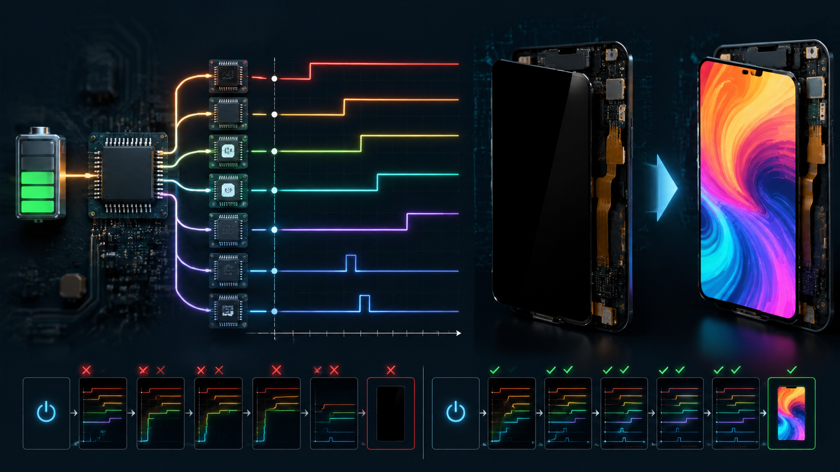
An AMOLED panel can stay completely black even when the OLED pixels and glass are not damaged. The display driver IC may be powered only partly, held in reset, left in Sleep In mode, blocked by an invalid interface state, or prevented from enabling its gate, source, and emission circuits. In each case, the visible result is the same: no light reaches the user.
Incorrect startup timing causes this failure because the DDIC, PMIC, host processor, and panel do not become ready at the same instant. A voltage may appear at the regulator output while remaining too low at the panel connector. Reset may be released before power-on reset and OTP loading finish. Commands may be sent before the interface accepts them. Emission power may start before the scan and source circuits are stable. The correct sequence is therefore a set of device-specific dependencies, not one fixed order for every AMOLED module.
The values in this guide are real published examples and one measured 7-inch module case. They show the size of the timing and voltage differences engineers may encounter, but they are not universal limits. Final limits must come from the exact panel specification, DDIC datasheet, PMIC datasheet, schematic, host-interface requirements, and approved initialization table used in the product.
Why timing creates a black screen: the panel only emits light after power, reset, internal startup, interface setup, initialization commands, image data, and emission control have all reached valid states. A failure at any earlier stage stops every later stage.
| Failure point | Electrical state | Why the screen stays black | Best proof |
|---|---|---|---|
| Input power | VCI, VDDI, or another required input is below its valid range | POR may not complete and internal regulators or references may not start | Connector-side voltage and input-current waveform |
| Reset | Reset releases before valid power or does not meet its pulse width | Registers, mode straps, and OTP-loaded values may not enter a known state | Reset waveform aligned with all required rails |
| Bias power | AVDD, AVEE, VGH, or VGL is missing or unstable | Source and gate circuits cannot write or scan the pixel array | Positive and negative bias waveforms plus PMIC fault state |
| Interface | MIPI DSI or SPI starts in the wrong state or at the wrong I/O voltage | The DDIC rejects or never receives initialization commands and frame data | Protocol trace, lane state, logic level, and command result |
| Commands | Sleep Out, vendor setup, or Display On is sent too early or omitted | The DDIC remains blanked, asleep, or incompletely configured | Timestamped command log and readable status registers |
| Emission power | ELVDD and ELVSS are absent, current-limited, or enabled at the wrong stage | Pixel current cannot flow even if scan and image data are correct | ELVDD-to-ELVSS differential and current under a known image |

Power Sequence
Power Rail Roles
Begin by drawing a power-domain map. Do not infer a rail's function from its name alone. In one display driver IC, VDDI may power the digital I/O pads while VCI powers analog and mixed-signal circuits. In another design, VCI may feed an internal regulator that generates additional core and panel-bias voltages. Some modules expose ELVDD and ELVSS directly at the connector, while other modules generate the emission supplies internally. VGH and VGL may be produced by an external PMIC, an integrated charge pump, or a chip-on-film power device.
The map should show the source of each rail, its load, its enable pin, its power-good or fault output, its expected operating window, and every signal that can inject current into that domain while the rail is off. Include the host processor's GPIO and interface pins because a high logic signal can back-power an unpowered DDIC through input protection structures. Also include load switches, FPC resistance, connector contacts, ferrite beads, current-sense resistors, and any shared supply used by touch, bridge, or timing-controller circuitry.
| Rail or signal name | Possible function in an AMOLED design | What must be verified | Possible failure evidence |
|---|---|---|---|
| VDDI or VDDIO | Digital I/O supply for MIPI, SPI, QSPI, DBI, reset, or GPIO pads | Valid input range, rise and fall limits, off-state voltage, logic thresholds, and back-power conditions | No command response, abnormal current before power-up, interface pins clamped, repeated reset |
| VCI | Analog, mixed-signal, boost-input, or internal regulator supply depending on the DDIC | Minimum operating voltage at the panel connector, load current, ramp requirement, and dependency on other rails | POR not completed, OTP not loaded, internal references unstable, black screen |
| AVDD or VSP | Positive analog or source-driver bias | Voltage window, ripple, soft-start, current limit, and tracking relative to negative bias | Incorrect grayscale, source-driver malfunction, line artifacts, startup fault |
| AVEE, VSN, or negative analog rail | Negative source-driver or analog bias | Negative regulation, discharge path, sequence, and absolute differential limits | Black or distorted display, stress during partial power, residual negative voltage |
| VGH and VGL | Gate-on and gate-off levels for panel scan circuitry | Actual DDIC or panel range, positive/negative tracking, startup overshoot, and load stability | Missing rows, horizontal bands, unstable scan, abnormal gate current |
| ELVDD and ELVSS | Positive and negative emission supplies for the OLED pixel current path | Voltage difference, current capacity, regulation under image load, enable order, and discharge requirement | No emission, dim image, brightness pumping, current limit, thermal shutdown |
| RESET or RESX | External hardware reset input, usually but not always active low | Polarity, pulse width, valid-supply relationship, release delay, and input voltage when VDDI is off | Undefined register state, intermittent boot, failure after rapid restart |
| PMIC enable and power-good | Controls rail startup and reports regulation status | Thresholds, propagation delay, deglitch time, default state, and firmware handling | Rail enabled too early, false-ready condition, incomplete shutdown |
A published 1.78-inch AMOLED module illustrates why a universal voltage table is unsafe. That module specifies a typical ELVDD of 4.6 V, a typical ELVSS of -2.0 V, a typical VDDIO of 1.8 V, and a typical VCI of 2.8 V. Its permitted ranges are not the same as the ranges used by every other AMOLED module.
| Published 1.78-inch module parameter | Minimum | Typical | Maximum | Engineering meaning |
|---|---|---|---|---|
| ELVDD | 3.0 V | 4.6 V | 5.0 V | Example positive AMOLED emission supply |
| ELVSS | -4.0 V | -2.0 V | 0 V | Example negative AMOLED emission supply |
| VDDIO | 1.65 V | 1.8 V | 3.3 V | External I/O supply for the module |
| VCI | 2.7 V | 2.8 V | 3.6 V | Analog supply for this specific module and DDIC implementation |
The same module also publishes load data. At 25 °C, 60 Hz, 500 nits, and a 100% white pattern, the typical emission-supply current is 27.9 mA, the typical VCI current is 6 mA, and the typical VDDIO current is 2 mA. In a 15 Hz, 50-nit, 10%-pixel-on idle condition, the published typical values are 2.8 mA for the emission path, 3.5 mA for VCI, and 1.2 mA for VDDIO. In deep standby, its maximum VCI and VDDIO currents are 15 µA and 4 µA, respectively. These numbers are useful as an example of mode-dependent loading, but they must not be copied into a different panel design.
Rail Dependencies
A black screen is an end symptom, not a diagnosis. The display may be black because no OLED current flows, because the DDIC remains in Sleep In mode, because initialization data was rejected, because the gate or source bias is missing, because the host never sends valid image data, or because the module repeatedly resets. The first task is therefore to identify the last startup stage that completed successfully.
A modern AMOLED DDIC may perform several internal operations after its external supplies enter range. These can include power-on reset, bandgap and oscillator startup, internal regulator startup, charge-pump sequencing, loading calibration or initialization values from OTP memory, establishing gate and source references, selecting interface mode, and preparing internal GRAM. The host must not assume that a rail crossing a threshold means the device can immediately accept every command.
| Startup stage | What can fail | What to measure or log | Typical visible result |
|---|---|---|---|
| External input power | Undervoltage, excessive rise time, overshoot, current limit, connector drop | Voltage at regulator output and panel connector, input current, enable timing | Black screen, cycling startup, intermittent boot |
| Internal POR and OTP load | Supply does not reach threshold, reset noise, host commands sent too early | Reset waveform, command start time, current step, readable ID or status register | No response, default configuration, inconsistent startup |
| Panel bias generation | Positive or negative rail absent, tracking error, PMIC fault, short or leakage | AVDD, AVEE, VGH, VGL, fault output, inductor current if accessible | Black screen, bands, rows missing, unstable grayscale |
| Emission power | ELVDD or ELVSS absent, insufficient voltage difference, current limiting | Both rails at panel connector under a controlled image pattern | No light, low brightness, brightness collapse on white image |
| Host interface | Wrong MIPI lane state, bad SPI timing, wrong I/O voltage, incorrect mode pin | LP and HS transitions, command packets, chip-select timing, logic levels | Black screen despite correct power, corrupted or frozen image |
| Command and display state | Vendor unlock omitted, Sleep Out delay violated, Display On not sent, bad table | Timestamped command log, readback, TE output, frame activity | Panel remains blank or only displays after a second reset |
Sequence faults often appear only under certain power conditions. A slow laboratory supply may hide a defect that appears with a fast battery load switch. A cold start may fail because converter startup is slower at low temperature. A rapid restart may fail because VCI, VDDI, or an internal rail has not discharged below the DDIC's reset threshold. A brownout can leave the host alive while the panel loses only one supply, creating an unsupported partial-power state.
Back-powering is another important mechanism. Suppose VDDIO is off but the host holds RESET, chip select, SPI data, or a MIPI-related control pin high. Current can flow through an input structure into the unpowered I/O domain. The voltage may be too low for normal operation but high enough to prevent a clean POR. A digital multimeter can miss this because the unwanted current may be small; an oscilloscope capture and current measurement during the off interval are more useful.
Use quantitative margins rather than visual judgment. For a voltage requirement, calculate the low-side margin as measured minimum minus specified minimum, and the high-side margin as specified maximum minus measured maximum. For a timing requirement, calculate measured delay minus the required minimum. A positive result is not automatically sufficient because probe error, temperature, load variation, and component tolerance still consume margin.
Measured Data
During debugging of one 7-inch AMOLED module, the VCI rail was specified to operate at 3.3 V but measured only 1.2 V while higher-voltage panel-bias rails were already active. The panel remained black. After the control logic was changed so that VCI reached its valid range before the dependent bias rails were enabled, the module initialized and displayed normally.
Data to publish for a real case: report the value at the panel connector, the measurement time relative to enable and reset, the image load, the temperature, and the number of repeated cycles. A voltage without these conditions is hard to reproduce.
| Recorded item | Minimum useful detail | Stronger evidence |
|---|---|---|
| Rail voltage | Minimum, nominal, peak, and connector measurement point | Full waveform with regulator output and panel connector on the same time base |
| Timing | Delay from a named threshold, such as 90% of VCI, to reset release or first command | Minimum, maximum, and average over repeated cold and warm starts |
| Load | Image pattern, brightness setting, refresh rate, and measured current | Black, gray, full-white, and switching-pattern results |
| Environment | Ambient temperature and input-supply voltage | Low, room, and high temperature plus input-voltage corners |
| Repeatability | Number of starts and number of failures | Automated cycle log with failed and passed waveform pairs |
| Change made | Firmware, resistor, capacitor, PMIC, or routing change | Before-and-after schematic or timing-state comparison |
| Case-study item | Before correction | After correction | What the evidence supports |
|---|---|---|---|
| VCI at the module | 1.2 V during startup | Reached the specified 3.3 V operating level before dependent rail enable | VCI undervoltage and dependency timing were relevant on this hardware |
| Panel-bias rails | Already active while VCI was invalid | Enabled only after the required VCI condition was met | The original firmware or enable logic violated this module's dependency |
| Display result | Black screen | Normal initialization and display | The corrective change resolved the observed failure |
This case supports a product-specific conclusion: on that 7-inch design, the bias rails must not be enabled while VCI is at 1.2 V. It does not support the universal statement that VCI must always be the first rail on every AMOLED module. A different DDIC may allow VCI and VDDI to rise in either order, may internally generate several bias rails, or may require a different dependency.
For example, the published SH8601A DDIC power diagram identifies VCI and VDDI as supplies that may be applied in either order. The same document states that its internal POR is generated within 1 ms after VDDI and VCI rise to 90% of their typical values, followed by a 5 ms wait before commands so that OTP loading can complete. Its power-on diagram also shows an internal power-on period greater than 80 ms. These values describe that DDIC implementation; they are evidence against treating one fixed generic delay as an AMOLED-wide rule.
A Texas Instruments AMOLED supply reference design gives another example of architecture-specific sequencing. In one configuration that uses AVDD, the design keeps the control signal low for about 5 ms while the preregulator and AVDD reach regulation, then starts ELVDD and ELVSS. The negative converter begins approximately 10 ms after the control signal rises. In the documented shutdown path, AVDD takes about 11 ms to power down before ELVDD and ELVSS are disabled. This example directly contradicts any claim that the emission rails must always be the first rails turned off.
To make the 7-inch case publication-grade, add the exact panel model, DDIC, PMIC, board revision, firmware revision, oscilloscope model, probe type, measurement points, ambient temperature, power source, image pattern, and number of repeated startup cycles. If product confidentiality prevents disclosure, state what information is withheld and avoid presenting unpublished limits as universal values.
Reset Timing
Safe Pin States
Before the first rail is enabled, every panel-related signal must have a known state. Review reset, PMIC enable, panel enable, mode-selection pins, SPI or QSPI chip select, data pins, MIPI lane state, tearing-effect connections, brightness control, and touch-controller pins. A signal should not float simply because the processor firmware has not configured its GPIO yet.
Check where each pull-up or pull-down resistor is powered. A pull-up to an always-on processor rail can drive a panel input before VDDIO exists. A pull-down that is too weak can allow noise to create a false edge on PMIC enable. A processor pin may briefly use its boot-ROM default function before application firmware runs. For each signal, document the hardware default, bootloader state, operating state, suspend state, shutdown state, and behavior during a processor reset.
| Signal | Pre-power requirement to document | Validation method |
|---|---|---|
| Hardware reset | Active polarity, guaranteed default, minimum pulse, release condition, and valid I/O domain | Trigger on first input rail and capture reset from power-off through first command |
| PMIC enable | Default level, threshold, delay, deglitch behavior, and whether firmware or hardware controls it | Capture enable, input supply, all generated rails, and power-good or fault |
| SPI or QSPI chip select | Inactive state before VDDIO, no unintended clocks or data transitions | Logic-analyzer capture beginning before rail startup |
| MIPI DSI lanes | Required low-power state during startup and reset, plus transition timing before HS transfer | Use a suitable D-PHY measurement solution or verified controller trace |
| Mode straps | Stable logic level during the DDIC's sampling interval | Measure the pin and compare against the supply ramp and reset release |
| Touch or bridge signals | No shared-rail back-powering or reset conflict | Measure off-state voltage and current with one subsystem powered at a time |
Reset timing must come from the exact device documentation. In the published 1.78-inch module example, RESETB is active low and the minimum low pulse width is 20 µs over its stated VDDIO and temperature conditions. In the SH8601A example, commands should wait 5 ms after internal POR to allow OTP loading. These two numbers apply to related published examples, not to all AMOLED products.
A robust firmware state machine should advance only when measurable conditions are satisfied. Avoid a single fixed delay that assumes every rail is healthy. Where hardware provides power-good or fault signals, read them. Where it does not, use delays derived from worst-case datasheet values and verified startup measurements, then include margin for temperature and component tolerance.
| Firmware state | Entry condition | Required check before advancing | Failure action |
|---|---|---|---|
| DISPLAY_OFF | System boot or requested shutdown | All panel enables inactive; host pins in specified state | Log unexpected off-state voltage or current |
| INPUT_POWER | Power request accepted | Input rails valid or required delay completed | Disable rails and report timeout |
| RESET_HOLD | Input rails starting | Reset pulse and supply relationship satisfy datasheet | Repeat controlled discharge before retry |
| BIAS_START | Specified dependencies met | Bias rails regulate without fault, overshoot, or current limit | Shut down in documented safe order |
| DDIC_READY | POR, reset, and internal delay complete | Optional ID or status read succeeds | Hardware reset once, then full power cycle if needed |
| INITIALIZE | Interface ready | All required commands transmitted successfully | Capture failed command index and bus status |
| DISPLAY_ON | Sleep Out delay and data preparation complete | Frame or TE activity detected; current consistent with image pattern | Keep emission disabled or execute controlled shutdown |
Rail Timing
A digital enable edge is not proof that a rail is valid. Measure the voltage at the panel connector, not only at the PMIC output pin. The connector measurement includes voltage loss across load switches, inductors, ferrite beads, current-sense resistors, PCB traces, connectors, FPC conductors, and ground-return paths.
For each rail, record turn-on delay, 10%-to-90% rise time, monotonicity, peak overshoot, minimum undershoot, steady-state ripple, settling time, load droop, shutdown fall time, and residual voltage before the next startup. For paired positive and negative rails, also record the differential voltage and any tracking requirement. A rail can individually remain within its absolute limits while the differential between two rails exceeds the DDIC or PMIC limit.
Published timing examples: the table below places several real values side by side. The large differences show why a generic 10 ms, 20 ms, or 50 ms delay cannot be treated as an AMOLED-wide rule.
| Device or document | Published value | What it controls | How to use it |
|---|---|---|---|
| SH8601A DDIC | Internal POR generated within 1 ms after VCI and VDDI reach 90% of their typical values | Beginning of the DDIC internal reset process | Use only with the stated SH8601A supply conditions |
| SH8601A DDIC | Wait 5 ms after POR before sending commands | Allows OTP data to load into internal registers | Do not replace a different DDIC command-ready time with this value |
| SH8601A DDIC | Internal power-on period shown as greater than 80 ms | Internal analog and display startup interval | Keep separate from the shorter POR and command-accept times |
| FLS-AMO-178-R585-A module | RESETB low pulse width at least 20 microseconds | External hardware-reset requirement | Verify voltage and temperature conditions in the module specification |
| FLS-AMO-178-R585-A module | TLPX at least 50 ns | MIPI DSI low-power timing parameter | This is interface timing, not the panel power-on delay |
| FLS-AMO-178-R585-A module | Clock settle 95 to 300 ns | MIPI DSI clock-lane transition timing | Check host D-PHY settings against this range |
| FLS-AMO-178-R585-A module | THS-EXIT at least 100 ns | MIPI DSI high-speed exit timing | Use for lane timing only |
| TI AMOLED supply reference design | Hold CTRL low about 5 ms while preregulator and AVDD regulate | Precondition before starting ELVDD and ELVSS in that design | Use only for the documented TPS65635-based architecture |
| TI AMOLED supply reference design | Negative converter begins about 10 ms after CTRL rises | ELVSS startup in that design | Confirm with the selected PMIC and component values |
| TI AMOLED supply reference design | AVDD takes about 11 ms to power down before ELVDD and ELVSS are disabled | Documented shutdown dependency | Evidence that one fixed universal shutdown order is unsafe |
| Metric | How to calculate or measure it | Why it matters |
|---|---|---|
| Connector voltage drop | PMIC output voltage minus panel-connector voltage at the same instant | Reveals path resistance and switching losses hidden by regulator-side measurement |
| Effective path resistance | Voltage drop divided by load current | Helps locate excessive connector, switch, trace, or FPC resistance |
| Overshoot percentage | 100 × (peak voltage minus nominal voltage) divided by nominal voltage | Quantifies stress instead of describing the waveform as merely fast |
| Low-side voltage margin | Measured minimum voltage minus specified minimum voltage | Shows remaining margin under load and temperature variation |
| Timing margin | Measured delay minus required minimum delay | Shows whether firmware and hardware tolerate worst-case startup spread |
| Residual off-state voltage | Voltage measured immediately before the next enable event | Indicates whether a rapid restart begins from a true power-off state |
For example, if a PMIC output is 4.62 V but the panel connector measures 4.50 V at 300 mA, the path drop is 0.12 V and the effective series resistance is 0.4 ohm. The corresponding path dissipation is 36 mW. That calculation does not identify the exact component, but it converts a vague observation into a measurable hardware problem that can be divided among the switch, connector, FPC, and ground path.
If a nominal 4.6 V rail peaks at 5.0 V, the overshoot is approximately 8.7%. Whether that is acceptable depends on the panel's maximum operating and absolute-maximum ratings, probe accuracy, and duration. Never approve a waveform only because the peak is brief; compare it with the device's transient limits if such limits are published.
Use a probe suitable for the voltage and edge rate. Minimize the ground loop on single-ended measurements. Use differential probing when the measurement reference is not safely at system ground or when checking the voltage directly between ELVDD and ELVSS. Verify probe attenuation and offset before capturing negative rails. If bandwidth limiting is used to evaluate ripple, save a second full-bandwidth capture so that startup spikes are not hidden.
Load condition matters. Capture at least a black image, a controlled mid-gray image, a full-white image, and a high-contrast switching pattern if the panel can display them safely. For an AMOLED panel, average current can change substantially with pixel content, brightness, refresh rate, and compensation mode. A rail that appears stable on a black image may collapse when a white pattern is displayed.
One published AMOLED PMIC example, the TPS65138, has a fixed 4.62 V positive output and a programmable negative output from -2.2 V to -6.2 V, with a stated 300 mA output capability. These numbers demonstrate that a compact mobile AMOLED power device can use much lower rail magnitudes than a large-panel design. They should be used only when the selected PMIC and panel require those values.
Command Timing
Power rails and hardware reset establish the conditions for communication, but they do not necessarily place the panel in normal display mode. The host may need to send a vendor-specific initialization table that configures interface mode, pixel format, scan direction, address mapping, gamma or compensation parameters, source and gate behavior, brightness control, current limits, refresh mode, and power-related registers.
A practical command flow often contains five distinct phases: hardware reset, a delay until commands are accepted, vendor-specific register initialization, Sleep Out, and Display On. Image data may be written before or after certain commands depending on the DDIC. Some controllers require one or more frame intervals after Sleep Out. Others load part of their configuration from OTP and require only a shorter host table. The exact command order must come from the approved vendor initialization sequence.
| Command-log field | What to record | Why it helps |
|---|---|---|
| Timestamp | Time from first rail enable or reset release | Allows direct comparison with oscilloscope waveforms |
| Command and parameters | Exact byte sequence, packet type, and payload length | Finds missing, duplicated, or corrupted initialization entries |
| Transport result | Controller status, timeout, ECC or CRC indication where available | Separates DDIC state problems from host-interface failures |
| Readback | Panel ID, power mode, display status, error flags, or vendor status | Shows whether the DDIC accepted commands and entered the expected mode |
| Power state | Power-good, reset level, measured rail state, and active image pattern | Connects software events with physical power behavior |
Do not describe MIPI DSI startup as a generic rule that a continuous reference clock must lock before reset. MIPI DSI normally uses defined low-power and high-speed lane states. The controller and panel specification determine the required startup state and when high-speed clock and data bursts begin. A published module example lists a minimum low-power period TLPX of 50 ns, a clock-settle interval of 95 to 300 ns, and a minimum high-speed exit time of 100 ns. Those are burst-interface timing parameters for that module, not a substitute for its millisecond-scale power and reset sequence.
During development, use failure injection to verify that firmware handles incomplete startup safely. Delay one PMIC enable, force one rail below its valid window, hold reset longer, omit one initialization command, or shorten the Sleep Out delay on a controlled bench setup. The goal is not to operate the panel outside its ratings, but to confirm that the system detects a failed condition, stops the startup sequence, records useful data, and performs a controlled retry instead of leaving partial power applied indefinitely.
Use a bounded retry strategy. A single hardware-reset retry may be appropriate when power rails and the interface are known to be valid. If that fails, execute a complete shutdown, wait until the required off-state voltages are reached, and then restart. Repeating rapid resets without discharging the power domains can hide the root cause and may create an unsupported state.
Black Screen Tests
Capture Waveforms
Begin black-screen diagnosis with synchronized waveforms rather than separate multimeter readings. A multimeter can confirm a steady voltage, but it cannot show whether a rail briefly overshoots, collapses during reset release, reaches regulation after the first command, or remains partially charged during a rapid restart.
Use enough oscilloscope channels to capture the main input supply, at least one critical DDIC supply, one bias or emission rail, reset, PMIC enable or power-good, and an interface activity indicator. If channel count is limited, keep one timing reference common across multiple acquisitions. Trigger on the first enable edge, reset transition, rail threshold, PMIC fault, or current spike depending on the suspected failure.
Minimum test coverage: collect both passing and failing traces. A single successful room-temperature startup does not establish timing margin.
| Test condition | Purpose | Recommended recorded data |
|---|---|---|
| Cold start after full discharge | Establish baseline startup from a known off state | All rail ramps, reset, first command, time to first valid frame, peak current |
| Warm restart | Check restart while the board and panel remain warm | Residual voltages, converter startup delay, command acceptance |
| Rapid off-on cycle | Expose incomplete discharge and POR problems | Off time, minimum rail voltage, reset behavior, startup success rate |
| Input-voltage minimum and maximum | Check PMIC headroom, current limit, and line transient response | Input current, all output margins, ripple, temperature |
| Low and high operating temperature | Expose delay, leakage, capacitor, and converter variation | Startup time distribution, minimum rail values, failure count |
| Black, gray, white, and switching patterns | Check load-dependent rail stability | Average and peak current, droop, ripple, brightness behavior |
| Brownout and host reset | Check partial-power recovery | Which domains remain powered, reset order, error flags, recovery path |
For engineering screening, repeat each important startup condition enough times to reveal intermittent behavior. One hundred cycles per condition is a practical development target when time permits, but it is not a universal qualification standard. Record the number of successful starts, failed starts, recovered starts, and failures requiring a complete power cycle. For low-rate intermittent defects, automated cycling with timestamped logs is far more informative than manual testing.
Use the same definitions across test runs. Define startup success as more than “the screen looked on.” A stronger criterion may require correct panel ID, no PMIC fault, valid TE activity, first frame within a defined time, stable current for a defined image, and no visible line or color defect. Define the measurement point and threshold for every reported voltage.
When a failure occurs, save the complete waveform and software log before retrying. A retry can erase the evidence. Also save one successful capture under the same condition. Comparing successful and failed traces often reveals a small delay or voltage difference that is difficult to notice in isolation.
Match Symptoms
Visual symptoms are useful for prioritizing measurements, but they are not reliable enough to identify one rail by themselves. A black screen does not prove the OLED layer is damaged, and a reddish or dim image does not prove one named rail is undervoltage. The symptom must be connected to electrical measurements, interface logs, and command state.
| Observed symptom | High-priority hypotheses | First measurements |
|---|---|---|
| Completely black with normal system operation | Emission supplies absent, DDIC in Sleep In, initialization rejected, no frame data, reset fault | ELVDD and ELVSS, reset, command log, panel ID or status, interface activity |
| Black only on some starts | Timing margin, floating enable, incomplete discharge, POR or OTP timing, intermittent connector | Failed-versus-passed startup waveforms, off-state voltage, success-rate statistics |
| Dim image or brightness collapse | Emission rail droop, current limit, brightness register, thermal protection, path resistance | Rail differential under white pattern, input current, PMIC temperature, brightness command |
| Horizontal or vertical lines | Gate/source bias instability, data integrity, FPC contact, panel damage | VGH, VGL, AVDD or AVEE, interface error, connector inspection |
| Flicker or periodic brightness modulation | Rail ripple, current limiting, repeated reset, frame synchronization, unstable refresh mode | Rail ripple synchronized to frame, TE signal, reset, PMIC fault, input supply |
| Color shift or incorrect grayscale | Gamma or compensation table, source bias, pixel format, data-lane error, panel temperature | Initialization table, readback, source-related rails, test-pattern comparison |
| Works after second reset | First reset too early, OTP or internal startup incomplete, command table begins too soon | Time from rail threshold to reset and first command, POR-related status |
A useful isolation sequence is: verify off-state voltage, verify external input supplies, verify reset, verify generated bias and emission rails, verify the host interface, read identification or status if possible, compare the command log, then test with a known pattern. This order prevents firmware and hardware teams from repeatedly changing unrelated parameters without evidence.
Current is often a valuable diagnostic channel. A nearly zero increase after Display On may indicate that emission power never enabled or the panel remained blank. Excessive current with no image may indicate a short, wrong bias, PMIC fault, or unintended all-pixel state. However, current must be interpreted using panel size, image pattern, brightness, refresh rate, and temperature. The published 1.78-inch module's 27.9 mA full-white example cannot be used as a pass/fail limit for a 7-inch module.
Do not tune voltages until the sequence and command state are known. Increasing a rail to make a marginal panel light can exceed the valid range and conceal a timing or connector problem. Use the nominal value and limits from the exact documentation, then solve the reason the measured value is outside that range.
Safe Shutdown
Power-off is not simply the reverse of a guessed power-on order. The correct shutdown depends on the DDIC, PMIC, and panel. Some designs require Display Off followed by Sleep In and a specified number of frames before external power is removed. Some PMIC architectures require one bias rail to fall before the emission rails. Other designs permit selected input rails to fall in either order after the internal display state has been changed.
Build the shutdown flow from four separate requirements: the command-state requirement, the host-interface state, the PMIC rail order, and the discharge threshold before restart. Do not merge them into one generic statement such as “always disable VCC first.”
- Send Display Off if required and confirm the command was transmitted.
- Wait the specified frame or command-processing interval.
- Send Sleep In if required and wait the specified interval.
- Place the host interface and GPIO pins in the documented inactive state.
- Disable external rails in the order specified by the panel and PMIC documents.
- Monitor the rails until they fall below the required off-state or POR threshold.
- Do not permit a new startup until the minimum off time and discharge conditions are met.
The published SH8601A example permits VCI and VDDI to be removed in either order after its documented display-off and sleep-in process. Its diagram includes frame-based waits before external power-off. The published Osptek module using that DDIC specifies that VDDI and VCI should be below 0.05 V when power is off. These details demonstrate why residual voltage must be measured rather than assumed.
Discharge time is determined by capacitance, load, active-discharge circuitry, leakage, and any current injected from other domains. When a rail approximately follows an RC discharge, voltage falls according to V(t) = V0 × e^(-t/RC). Real display rails may not follow a simple exponential because PMIC active discharge, converter body paths, panel load, and GPIO injection alter the curve. Use the equation only as an estimate, then verify the actual waveform.
Test abnormal events deliberately within safe limits: sudden battery removal, processor reset while panel power remains on, PMIC fault, brownout, watchdog reset, and rapid user power cycling. The system should either maintain a valid display state or execute a controlled recovery. It should not leave high-voltage bias active indefinitely while the DDIC input supplies or host interface are invalid.
| Abnormal event | Risk | Design response to verify |
|---|---|---|
| Host processor resets while PMIC remains enabled | Panel receives invalid or floating interface signals | Hardware defaults keep reset and enables safe until firmware recovers |
| Battery or input supply collapses | Rails fall in an uncontrolled order | PMIC undervoltage lockout and discharge produce a documented safe state |
| Rapid off-on request | POR does not retrigger because one rail remains charged | Firmware waits for measured or guaranteed discharge before restart |
| One generated rail faults | Partial power remains applied | Fault handling disables dependent rails and records the failing domain |
| Connector intermittently opens | One rail or signal disappears before others | System limits repeated retries and prevents sustained abnormal bias |
Final engineering checklist:
- Identify the exact panel, DDIC, PMIC, board revision, and firmware initialization table.
- Create a rail-and-signal dependency map rather than copying a generic sequence.
- Measure at the panel connector under realistic image load.
- Capture reset, enables, power-good, rail voltages, command timing, and interface activity on a common time base.
- Calculate voltage, timing, overshoot, path-resistance, and discharge margins.
- Validate cold start, warm start, rapid restart, voltage corners, temperature corners, and abnormal power loss.
- Use a bounded retry and full-discharge recovery strategy.
- Publish real test conditions and do not present one module's values as universal AMOLED limits.
Leave a comment
This site is protected by hCaptcha and the hCaptcha Privacy Policy and Terms of Service apply.