


Best Display for Battery Devices | E-Paper, PMOLED & Low Power LCDs
E-paper is the preferred choice for battery-powered devices, with its static display power consumption as low as 0W, consuming power only during screen refreshes.
If high-contrast luminescence is required, the backlight-free PMOLED operates at a power consumption of only about 15 milliwatts.
Low-power Memory LCDs have a static power consumption of around 10 microwatts, combining high refresh rates with sunlight readability. These three technologies perfectly cater to different battery life requirements.
E-Paper
Taking a 2.9-inch screen as an example, it generates an instantaneous operating current of 3 to 5mA only during the 0.3 to 1.5 seconds of image refreshing.
Under direct outdoor sunlight of 100,000 lux, thanks to a reflectance of over 40%, the contrast ratio remains stable at around 15:1.
If powered by a single 230mAh CR2450 coin cell battery, based on 5 partial refreshes per day without turning on the front light, the theoretical battery life of the device is 5 to 7 years.
Power Consumption & Battery Life
The physical foundation of e-paper displays is the movement of charged particles within microcapsules. Once the electric field disappears, these particles, about 100 microns in diameter, are fixed in place by van der Waals forces. This physical characteristic results in a measured power consumption of 0.00uA for the display module itself when the image is not being refreshed.
Unlike LCDs or self-emissive OLEDs that require continuous charge refreshing, e-paper only draws current during the 250 to 1500 milliseconds it takes to change the pixel arrangement. In a typical 2.13-inch electronic shelf label system, the standby current is primarily determined by the deep sleep mode of the Microcontroller Unit (MCU), usually maintained between 1.5µA and 3µA.
| Power Consumption Component | Typical Current Value | Duration |
|---|---|---|
| Deep Sleep | 1.8 µA | 99.9% of the usage cycle |
| SPI Communication Data Update | 2.5 mA | 50 - 100 ms |
| Internal Charge Pump | 6.0 mA | 100 - 300 ms |
| Screen Refresh Drive | 8.0 mA | 600 - 1200 ms |
Driving e-paper requires boosting the battery voltage (typically 3V) via an internal charge pump to a high voltage of around +15V or -15V to propel the particles. The energy conversion efficiency during this step-up process is approximately 80% to 85%, and this energy loss becomes noticeable in frequently refreshed devices.
Take a 220mAh CR2032 coin cell battery as an example. Assuming the system performs 4 global (full) refreshes a day, a single refresh consumes about 0.003mAh of power. Combined with a 2µA static leakage current, this battery is sufficient to power the device for more than 5 years, with the power primarily consumed by the battery's natural self-discharge rather than the screen display.
| Refresh Mode Comparison | Peak Current | Energy Consumed (Per Frame) | Applicable Scenarios |
|---|---|---|---|
| Black/White Global Refresh | 12 mA | 15.0 mJ | Initial screen load |
| Four-Color Partial Refresh | 18 mA | 45.0 mJ | Price/status fine-tuning |
| Fast Partial Refresh | 5 mA | 3.5 mJ | Digital clock update |
The proportion of energy distribution varies hugely across different applications. In a sensor terminal that refreshes once every 10 minutes, the display module accounts for 15% of the total energy budget. If the refresh frequency is reduced to once a day, the display's share drops to about 0.2%, at which point the battery's self-discharge rate becomes the limiting factor for battery life.
This low-frequency interaction characteristic gives e-paper a significant advantage in the logistics label sector. Using a 1000MHz SPI bus to transmit a 200x200 pixel bitmap takes only 20 milliseconds, meaning most of the electrical energy is spent waiting for the mechanical process of particles moving into position.
-
Driving Voltage: Driving Integrated Circuits (ICs) typically require a 2.4V to 3.7V input, internally converted to bipolar high voltages.
-
Temperature Fluctuations: In a 0℃ environment, fluid viscosity increases, extending the refresh time from 1.2s to 4.5s, and concurrently tripling power consumption.
-
Self-Discharge Coefficient: Standard lithium batteries self-discharge at about 1%-2% per year. The ultra-low power nature of e-paper devices makes this natural leakage a significant factor.
-
Front Light Gain: If an LED front light is turned on at 50% brightness, the instantaneous current jumps to 20mA - 30mA, slashing a multi-month battery life to under 100 hours.
-
Communication Overhead: Instantaneous peaks during Bluetooth Low Energy (BLE) connections can reach 15mA. When updating screens wirelessly, the radio components often consume more power than the screen refresh itself.
On a 6-inch e-reader equipped with a 1500mAh lithium-polymer battery, approximately 8,000 to 12,000 page turns can be completed with Wi-Fi and front light turned off. Assuming a reading speed of one page per minute, continuous reading time can reach 150 to 200 hours, over 10 times higher than the 10-15 hours of screen-on time for a smartphone.
-
1.54-inch Price Tag: Uses 2 CR2450 batteries, targeting a 10-year lifespan, with total refreshes limited to under 30,000 times.
-
13.3-inch Signage: Employs solar panels paired with a 5000mAh battery, relying on 100,000 lux of natural light for charging current, theoretically achieving infinite battery life.
-
Smart Wearable Strap: Paired with an MCU featuring low-power SRAM built into the pixels, bringing the standby current down to 0.9µA.
The refresh algorithm of e-paper directly affects power consumption. Because microcapsules are extremely sensitive to voltage, precisely controlling the width of voltage pulses through Waveform files can reduce unnecessary charge flow by 40%, thereby extending battery life without modifying the hardware.
Compared to PMOLEDs, which consume milliwatts of energy every second, e-paper behaves more like real paper when static. It finds an extremely narrow balance between spatial footprint and power demands, especially in off-grid devices where a single battery cycle needs to cover over 3,000 display updates. This advantage amplifies exponentially as the usage life cycle lengthens.
Impact of Ambient Light
The physical basis of e-paper display relies on reflecting external light sources. Its surface polymer film refracts light into the microcapsules. White particles coated with titanium dioxide (TiO2) float to the top layer under a positive electric field, reflecting 40% to 45% of incident light back to the observer. In contrast, LCD panels in pure reflective mode have their reflectance suppressed to between 5% and 8% after light passes through multiple polarizer layers.
Outdoors in California at noon, ambient illuminance typically surges to 100,000 Lux. Light Emitting Diode (OLED) screens often suffer color washout under identical sunlight, whereas the black-and-white contrast ratio of e-paper climbs to a physical peak of 15:1. As the number of incident photons increases, the diffuse reflected beams scattered by the white microcapsules intensify, significantly reducing visual aliasing on text edges.
When light hits the micro-frosted anti-glare glass, uniform Lambertian scattering occurs. Even at extreme viewing angles up to 178 degrees from the central normal, the screen brightness decays by less than 10%. Conversely, OLED panels exhibit a 30% brightness drop and noticeable blue shifts when viewing angles exceed 60 degrees.
-
Office Fluorescent Lights: At 500 Lux illuminance, black-and-white e-paper reflection brightness is about 200 nits, equivalent to 70-gram standard printing paper.
-
Overcast Outdoor Environment: At 10,000 Lux ambient light, there is no specular reflection on the screen surface, and the contrast ratio is maintained around 12:1.
-
Under Low-Illuminance Streetlights: In a 30 Lux environment without an external light source, the naked eye can only distinguish bold headlines larger than 24pt.
When external illuminance drops below 50 Lux, reading on a physical reflective screen causes visual fatigue. The space beneath the e-paper substrate is packed with dense Thin-Film Transistor (TFT) circuit layers, making it impossible to install a backlight module. Instead, engineers overlay a 0.5mm thick acrylic Light Guide Film on the outermost layer of the screen.
5 to 7 Surface-Mounted Device (SMD) LEDs attached to the bottom bezel emit light sideways. Once the light enters the Light Guide Film, total internal reflection is disrupted by surface-etched nano-scale dots, projecting the light downwards evenly at a 45-degree angle onto the microcapsule layer, which then reflects it back to the human eye.
Turning on the front light completely alters the device's power consumption profile. Setting the front light to 50% brightness—with internal optical losses in the light guide plate at about 20%—the continuous operating current of the LEDs reaches 18mA to 25mA. For a system with a static drain of 0µA, the overall battery life would plummet from 8 weeks down to under 30 hours.
Color e-paper (such as Kaleido technology) layers a Red, Green, and Blue (RGB) Color Filter Array (CFA) over the monochrome microcapsules. Ambient light suffers about a 60% attenuation during the round trip of penetrating the color filter to reach the white particles and reflecting back. Under the same 1000 Lux indoor lighting, the visual brightness of a color panel is 1.5 stops darker than a pure black-and-white panel.
To compensate for the 30% loss in color saturation, the system relies on the front light for brightness compensation. The device tweaks the color temperature of the white LEDs from a standard 4000K up to a cold white 6500K, boosting the transmission in specific wavelength bands of the RGB filters.
-
White State Reflectance: After adding the CFA layer, the absolute reflectance of pure white areas drops from 45% to 15% - 20%.
-
Color Gamut Performance: Under direct outdoor sunlight, NTSC color gamut coverage maxes out at 10% - 15%.
-
Front Light Compensation Value: Turning on 100% front light at night causes the color filter to scatter and diffuse about 20% of the light.
Exposure to high-intensity Ultraviolet (UV) rays disrupts the chemical fluid stability inside the microcapsules. Long-term exposure to UV rays with wavelengths below 380 nm causes the transparent capsule shells to yellow. Industrial-grade outdoor signage requires an outermost 0.2mm anti-UV protective film to block UV penetration to below 1%.
Sun exposure brings not only high illuminance but also raises the panel's surface temperature. When localized screen temperatures exceed 50°C, the viscosity of the internal electrophoretic fluid plummets, causing black and white particles to mix easily. This rapidly degrades the 15:1 contrast ratio down to 7:1.
42-inch traffic signs deployed along Texas highways integrate infrared temperature sensors and fans internally. When the surface temperature sensor detects values exceeding 45°C, the fans activate to circulate heat, preventing the combination of high temperatures and intense light from causing irreversible phase changes in the electrophoretic fluid.
The roughness parameter (Ra) of the Anti-Glare (AG) coating is strictly controlled between 0.15 and 0.2 microns. Too high a value decreases the refractive index, turning white backgrounds gray. Too low a value causes specular reflection, creating glaring hotspots under 500 nits of indoor spotlights. Engineers must strike an optical compromise between clarity and anti-reflection.
Refresh Rate & Temperature
E-paper pixels are composed of charged microparticles suspended in a transparent hydrocarbon solvent. When a 15V voltage is applied, 1-micron diameter titanium dioxide white particles move through the viscous fluid; this entire physical displacement takes 250 to 500 milliseconds. LCD liquid crystal molecules deflect in just 5 milliseconds. The electrophoretic physical structure hard-locks the upper limit of the refresh rate between 2Hz and 4Hz.
High-frequency localized data updates can trigger ghosting (image retention), as particles cannot fully return to their initial physical state under multiple rapid voltage pulses. A Waveform Look-Up Table (LUT) built into the controller outputs reverse voltages, utilizing a 1200-millisecond global black-and-white flash to force all charges back into place. Engineers configure the factory standard for 6-inch e-readers to perform a 1.5-second global clean every 5 page turns to erase the 5% grayscale artifacts left by previous pages.
-
Black & White Global Update: Takes 900 to 1200 ms, showing alternating black and white flashes to thoroughly clear ghosting.
-
Monochrome Partial Update: Takes 250 to 300 ms, for fast changes within a specific area, suitable for following text input.
-
A2 Fast Mode: Takes 120 to 150 ms, completely abandoning grayscale gradations to retain only pure black and pure white.
-
Multi-Color Panel Drive: Takes 12 to 15 seconds, repeatedly pulling red and yellow particles into position using high and low-frequency voltages.
Particle movement speed is tightly bound to the solvent's physical viscosity, making ambient temperature the primary variable interfering with charge efficiency. Standard e-paper panels are rated for an operating temperature range of 0℃ to 50℃. In a standard 25℃ laboratory, an MCU outputting a 300-millisecond waveform pulse enables the panel to reach its nominal 15:1 black-and-white contrast ratio.
When winter temperatures in Oslo, Norway, plunge to -5℃, the viscosity of the hydrocarbon solvent increases logarithmically. What was a 0.5-second page turn slows to 4.5 seconds, and white backgrounds turn 30% gray because particles cannot move into position. To counter the cold, bus stop signs deployed outdoors in Northern Europe attach 12V Polyimide (PI) heating films to the back of the panels.
If a temperature sensor (like the LM75A) detects panel back temperatures dropping below 0℃, the system injects a continuous 2A current into the heating film for 3 seconds before a display change. Only after the localized temperature is forcibly raised to 10℃ does the MCU issue the 15V drive pulse for image redrawing. The power consumed by a single heated refresh in freezing conditions is 40 times that of normal operation at 20℃.
-
-15℃ Extreme Cold Zones: Internal solvents freeze completely; the system prohibits power delivery to prevent high voltages from breaching the Thin-Film Transistors.
-
0℃ to 10℃ Range: Specific low-temperature waveform files must be invoked, doubling the duration of applied voltage.
-
10℃ to 30℃ Range: The panel's optimal operating temperature zone, offering the highest reflective contrast and dropping drive power consumption to its lowest point.
-
50℃ to 60℃ Range: Extreme high-temperature state where microparticles are highly susceptible to irreversible physical agglomeration.
Summer surface temperatures in the Nevada desert regularly breach 45℃, causing the electrophoretic fluid to thin out too much. Particles drift further than predefined under the same voltage, causing areas that should display light gray to appear much darker due to the over-ascent of black particles. The Drive IC invokes a high-temperature LUT waveform table, truncating the 15V pulse width from 250 ms to 150 ms to prevent image overexposure from excessive response.
Three-color (black, white, red) e-paper is even less forgiving of temperature fluctuations. Red particles differ drastically in volume and mass from black and white particles, and their separation process requires an extremely complex combination of voltage frequency bands, taking up to 15 seconds. In environments below 10℃, particles of different masses easily interfere with each other in the viscous fluid, causing red areas to darken and turn 20% to 40% gray.
Texas highway speed limit signs, heavily deploying 32-inch monochrome e-panels, are equipped with double-layer insulated glass and 5000 RPM industrial-grade micro-cooling fans within their aluminum housings. When infrared thermal cameras register surface temperatures hitting 48℃, the fans spin up within 2 seconds to force air convection, rigidly suppressing the temperature gradient on the panel's front face safely within operational limits.
-
Built-in Thermal Probes: The driver board samples absolute ambient air temperature data at high frequency every 1 second.
-
Multiple Preset Parameter Tables: Over 100 sets of highly precise drive pulse tables from -5℃ to 50℃ are baked into memory.
-
Peak Dynamic Tweaking: Based on returned temperature difference data, peak voltage outputs are dynamically scaled up or down between 10V and 15V.
Tailored for the harsh environments of extremely cold regions, material engineers developed dedicated Wide Temp panels. By adjusting the chemical solute ratio of the hydrocarbon solvent inside the microcapsules, the fluid's physical freezing point is pushed down to -25℃. In unmanned weather stations in Alaska, wide-temp panels can independently redraw barometric data within 3 seconds during a -20℃ blizzard, without any external electric heating.
PMOLED
PMOLED lacks a TFT panel layer, making manufacturing costs 30%-40% lower than conventional mobile phone screens.
It illuminates pixels by intersecting row and column electrodes, with an emission response time in the 10-microsecond range.
For battery-powered devices, power consumption is dictated by the proportion of illuminated pixels.
When pure black backgrounds account for 70%, the operating current of a 0.96-inch monochrome screen is a mere 1-2mA.
Because the current required by the passive scanning mechanism rises linearly with size, it is typically restricted to micro devices under 3 inches.
On-Pixel Ratio
A monochrome panel with a 128x64 resolution contains 8,192 independent organic light-emitting diodes. When the main control chip issues a command to turn off the entire dot matrix, the panel enters sleep mode, and the power drain for the whole screen is just 0.5 microamps. Applying a 3.3V drive voltage to a single pixel to hit a brightness of 100 nits consumes about 0.2 microamps of current. Rendering a standard 16x16 pixel battery icon requires 150 pixels; illuminating this icon alone draws around 30 microamps of operating current.
The bright area has a specific mathematical correlation with the battery system load:
-
10mAh coin cell system: Interface high-brightness areas are capped below 5%.
-
100mAh polymer lithium battery: Maintaining 14 days of standby requires keeping the emission ratio around 25%.
-
SPI communication bus: Transmitting 8-bit pure black data frames reduces pin toggle power consumption on the main controller.
-
Boost converter efficiency: If the illuminated area exceeds 50%, DC-DC conversion efficiency plummets to 60%.
Software engineers purposely design dark user interfaces based on hardware specs. A weather station display panel uses 24-pixel-high fonts to show temperature readings, occupying 12% of the screen's physical area. The remaining 88% black area completely avoids drawing current, with the emissive layer remaining physically switched off.
Drastically increasing the proportion of active pixels yields an exponential spike in power consumption. When the emission ratio is dialed up from 10% to 50%, voltage drops occur along the row electrodes inside the panel. The built-in charge pump chip must run at full load to maintain a 9V output voltage, causing the instantaneous power draw of the entire screen to soar to 15 milliamps.
High-load operation translates into thermal energy pooling within minuscule spaces. Running a 1.5-inch panel continuously at an 80% emission rate for 5 minutes generates 0.3 watts of heat. Consequently, the panel surface temperature climbs by 4 degrees Celsius. Accumulated heat forces the display driver to automatically scale down the global contrast from 0xFF to 0x7F by modifying the 0x81 register.
Development teams usually employ specific coding strategies to suppress full-screen emission rates:
-
Use hollow outline fonts instead of solid bold fonts.
-
Set progress bar widths to 1-pixel lines.
-
Implement checkerboard dithering algorithms instead of solid background color fills.
-
Forcefully dim the brightness of inactive UI elements down to 10 nits.
-
Utilize the 0xAE command to shut down non-essential zones during idle periods.
The internal resistance of a CR2032 coin cell is as high as roughly 15 ohms. An all-white screen (100% emission rate) will instantaneously pull a peak current of 30 milliamps. Heavy current discharge drops battery voltage from 3.0V to 2.4V, triggering the Surface-Mounted Device (SMD) microcontroller's brown-out reset threshold and rebooting the device.
Screen refresh rates weigh heavily in the energy consumption model for illuminated areas. Updating frames at 60 fps with a 20% emission rate demands the MCU to constantly write to Video RAM (VRAM) via data lines. Dropping the refresh rate to 10 fps shortens the controller's wake time, relying on the display's internal RAM to hold a static image output and sustain a steady 2 milliamp current.
A specific dive computer houses a 2.08-inch display module. In environments 50 meters underwater, the screen outputs real-time depth and tank pressure data using a 15% active emission area. The device's internal 400mAh battery supports up to 48 hours of continuous screen-on operation.
The Bill of Materials (BOM) for peripheral circuitry is equally bottlenecked by the expected maximum emission area:
-
Charge pump capacitor capacity: Normally provisioned between 1μF and 4.7μF.
-
FPC ribbon cable copper trace width: Requires at least 0.1 mm trace width to handle 50mA peaks.
-
Blue material longevity: At high emission rates, blue pixels decay 20% faster than green ones.
-
EMI shielding design: Switching noise under heavy loads necessitates adding 0.05 mm thick shielding tape.
10,000 Lux of glaring outdoor light requires the panel to pump out 500 nits of brightness. Under a 500-nit operating profile, the emission rate must be strictly clamped below 5% to avoid breaching the panel's 50 milliamp physical current ceiling. Ambient light sensors hooked into the hardware circuit rewrite contrast register data on the fly based on illuminance.
Driver chips supporting 4-bit grayscale displays offer 16 levels of brightness adjustment. Using Pulse Width Modulation (PWM) to pin a single pixel's brightness to level 8 (50% duty cycle) halves average power draw. Broadly employing grayscale gradient backgrounds over pure white fills saves approximately 40% in energy reserves.
The long-term physical aging trajectory of panels is directly proportional to emission rates. Emitting light continuously for 5,000 hours at an emission rate above 60% incurs a 30% irreversible decay in the brightness of emissive materials. Pixels parked in a pure black state suffer zero physical wear. Low-level software runs pixel-shifting routines, nudging image coordinates by 1 pixel on the X or Y axis every 60 seconds to diffuse localized material aging strain.
Hardware Parameter Comparison
PMOLED panels strip away the liquid crystal layer and polarizer structures, generally compressing thickness down to between 1.2 mm and 1.5 mm. Conventional low-power LCD modules outfitted with glass substrates run up to 2.8 mm thick. Eradicating the need for auxiliary LED backlight beads and light guide plates drops the weight of a bare 0.96-inch screen to a mere 1.5 grams.
Inside the confined spaces of a 35 mm diameter smart band dial, a 1.5 mm thickness discrepancy gives engineers room to wedge an extra 40mAh polymer lithium battery onto the rear of the PCB.
Hardware tier streamlining drastically alters pixel state switching mechanics. Lacking the mechanical twisting phase of liquid crystal molecules, the electro-optical conversion response time of organic light-emitting diodes universally falls under 10 microseconds. When bistable e-paper executes a full-screen refresh of a 200x200 image, the electrophoretic maneuvering of ink capsules eats up 1.5 to 3 seconds.
-
60Hz Framerate: The master chip pushes data over the SPI bus at an 8MHz clock frequency, yielding image transitions free of visual ghosting.
-
1Hz Refresh: Low-power LCDs cling to images using 1-bit SRAM built into the pixels, netting a measured static current of 5 microamps.
-
0Hz Power Draw: When e-paper is severed from 3.3V logic power, 120x120 pixel coordinate data physically persists indefinitely.
Temperature swings inject interference into the physical viscosity of different display mediums. On a ski speedometer at minus 20 degrees Celsius, LCD panel response latency stretches violently from 10 milliseconds to well past 300 milliseconds. Sub-zero e-paper demands an internal heater drawing 50 milliamps to thaw electrophoretic fluid vitality.
Under brutal -40°C extreme cold, PMOLED's internal carrier mobility only slips by 5%; a 0.5-second countdown timer on screen robustly clings to its 60 fps physical refresh rate.
Variances in luminescent mechanisms birth radically divergent optical contrast parameters. Because underlying pixels shut down on a physical level to display black, the panel's contrast test scores smash through 10,000:1. Low-power reflective LCDs depend entirely on external ambient light penetrating and refracting, pinning their contrast ratios fluctuating between 15:1 and 30:1.
-
Emission Brightness: By tweaking the controller's 0x81 register, monochrome panel peak brightness maxes out from 100 nits to 150 nits.
-
Viewing Angles: Self-emissive properties afford viewing angles exceeding 160 degrees across all four directions without color shift.
-
Ambient Light Immunity: Under 10,000 Lux outdoor sunshine, un-treated glass surfaces lacking anti-glare coatings kick back 60% reflections.
To sustain high-brightness outputs, driver circuit voltage settings adhere to strict physical boundaries. The internal charge pump fused into the SSD1306 control chip must step up 3.3V logic inputs to between 7V and 9V to energize base pixels. This DC-DC boost conversion bleeds off about 15% to 20% of energy as heat loss.
Sharp MIP screens uniformly peg logic levels and drive levels at 3.0V, physically sidestepping the dozens of microamps in standby power leakage spawned by boost circuits.
Continuous high-voltage driving accelerates the aging of organic materials. Rated at 100 nits, the half-life of blue pixels (time until brightness dims to 50% of the initial value) hovers around 10,000 hours. Green emissive materials exhibit superior physical longevity, eclipsing 30,000 hours of continuous uptime.
-
Temperature Accelerated Aging: Baking inside an 80°C oven for 240 continuous hours induces an irreversible 15% drop in panel brightness.
-
Localized Burn-in: Static pixels fired up for 500 continuous hours will foster a physical brightness disparity of 10 nits against neighboring dormant pixels.
-
UV Degradation: Left unprotected without a UV coating outdoors for 30 days drops the color saturation of emissive materials by 8%.
Hardware routing engineers evaluate data interface bandwidth redundancies. On a 1.3-inch 128x64 screen, a single frame of pure monochrome graphics hogs 1,024 bytes of VRAM. Running an I2C bus at 400kHz devours roughly 25 milliseconds of clock cycles to pipe through one frame.
Shifting the hardware interface to a 4-wire SPI protocol cranks the clock pin toggle frequency up to 10MHz, squashing the 1,024-byte write time per frame under 1 millisecond.
Swift bus transfers let the MCU retreat to sleep mode faster. In low-power beacons juiced by 20mAh coin cells, the master chip plunges into a 0.3-microamp deep sleep instantly after shoving data. An oscillator buried inside the panel maintains a 105Hz hardware scan rate, autonomously preserving the display output.
Electrostatic discharge (ESD) survivability is a mandatory testing box to check for outdoor wearable hardware. Conventional bare-die panels only muster a Human Body Model (HBM) ESD tolerance of 2000V. Hardware schematics dictate parallel-wiring a 0.1 microfarad X5R ceramic capacitor between the VCC and GND pins of the FPC ribbon cable.
This 0402 package capacitor intercepts and absorbs voltage spikes from 8000V contact discharges, shielding the controller from being fried by 30-ampere split-second discharge currents. Absent physical protection, static arcs shred the column drivers' shift registers in under 5 nanoseconds, scarring the screen with a permanent 1-pixel wide vertical bright line.
Low Power LCDs
Low-power LCDs include MIP (Memory-in-Pixel) and transflective panels.
MIP technology embeds a 1-bit SRAM in each pixel, maintaining a static image power consumption of only 1 to 5 microwatts, which is 0.5% of a transmissive TFT-LCD.
It provides a 30Hz to 60Hz refresh rate, with no visual ghosting during image transitions.
Transflective LCDs feature an ambient light reflectance of 20%, making them clearly readable under 100,000 lux of direct sunlight.
In devices equipped with a 200mAh battery, these panels support 20 to 30 days of always-on display.
Display panel power consumption
Based on the 1.2-inch to 1.3-inch display panel size benchmark for wearable devices, there are order-of-magnitude differences in the physical and electrical parameters among different display architectures. Transmissive TFT-LCDs require continuously driving the LED backlight module, and the overall operating current of the panel usually ranges from 8mA to 10mA. Transflective LCDs can turn off the backlight when external illuminance exceeds 5,000 lux, relying on natural light reflection to maintain the display, dropping the operating current to 1.5mA to 2mA. MIP panels have a 1-bit SRAM circuit built into each pixel; the current required to maintain a single static frame is merely 2µA to 5µA.
| Parameter Dimension | 1.28" MIP Panel (Monochrome) | 1.2" Transflective LCD | 1.3" Transmissive TFT-LCD |
|---|---|---|---|
| Static Drive Current | 2µA | 1.5mA (Backlight Off) | 8.5mA |
| Dynamic Current (60Hz) | 45µA | 1.8mA (Backlight Off) | 9.2mA |
| Typical Logic Voltage | 3.0V / 3.3V | 2.8V / 3.3V | 1.8V / 2.8V |
| Ambient Light Reflectance | 28% | 18% | < 2% |
| Typical Contrast Ratio | 25:1 | 40:1 | 800:1 |
| Black/White Response Time | 10ms (25°C) | 15ms (25°C) | 25ms (25°C) |
The electrical energy consumption of the panel increases linearly with the screen refresh rate. Mass-produced by Sharp, the LS013B7DH03 1.28-inch MIP screen has an overall power consumption of 5 microwatts while holding a static image. When the device drives the panel to update the second hand's position at a 1Hz frequency, power consumption rises to 15 microwatts. When the system refreshes at full 60Hz for UI scrolling operations, the panel's power consumption increases to 135 microwatts.
MIP and transflective panels achieve ambient light utilization by depositing an aluminum or silver-based reflective film layer at the bottom of the liquid crystal layer. The extreme physical reflectance of a monochrome MIP panel can reach 32%. Under 100,000 lux of direct sunlight at noon, the screen's surface brightness is equivalent to a 3,000-nit self-luminous body. The reflective film of a transflective panel is covered with light-transmitting micropores, with the transmission-to-reflection area ratio typically set at 3:7 or 4:6, placing the ambient light reflectance in the 15% to 20% range.
Natural light suffers optical energy loss when passing through polarizers, glass substrates, and color filters. Color MIP panels rely on RGB sub-pixel filters to synthesize colors, increasing the light transmission path and causing the overall reflectance to drop to around 12%. The color depth of color MIP screens is limited to 3-bit (8 colors) or 6-bit (64 colors). Their NTSC color gamut coverage is below 10%, making it impossible to reproduce highly saturated pure colors.
The contrast ratio parameters of low-power LCDs are constrained by their reflective operating principles. Transmissive TFT-LCDs achieve an 800:1 contrast ratio with the help of high-brightness direct-lit backlights. For monochrome MIP screens, because the reflective film cannot completely absorb stray light, the black in the dark state appears as a dark gray with a reflectance of about 1% to 2%. The maximum measured physical contrast ratio of such panels is 25:1, while the contrast ratio of color transflective panels fluctuates between 15:1 and 20:1 when the backlight is turned off.
The physical response time of the screen is controlled by the deflection speed of liquid crystal molecules. At a standard room temperature of 25°C, JDI's 1.2-inch MIP panel takes 8 to 10 milliseconds to complete a single black-and-white state switch. When the device plays animations at 60 frames per second, the duration of a single frame is 16.6 milliseconds, and the panel's response speed is sufficient to avoid visual ghosting. In contrast, E-ink screens require 300 to 450 milliseconds to complete a full-screen electrophoretic particle flip.
Drastic changes in ambient temperature will alter the viscosity coefficient of liquid crystal materials. In outdoor extreme cold working environments of -20°C, the deflection resistance of liquid crystal molecules in low-power LCDs increases. The actual response time extends from 10 milliseconds to 150 or even 200 milliseconds. When users wearing Garmin Enduro watches scroll quickly through pages while skiing, a slight smearing phenomenon will appear on the screen.
There is a mutually restricting physical mechanism between panel pixel density (PPI) and micro-power characteristics. The resolution of a 1.28-inch monochrome MIP panel is set at 176×176, yielding a pixel density of about 194 PPI. To increase the resolution to 454×454 (about 500 PPI) within the same physical dimensions, the number of built-in SRAM memory cells must increase by 6.6 times. The rise in transistor density leads to increased internal leakage current, pushing the panel's static maintenance power consumption past 50 microwatts.
Most industrial-grade and wearable-grade low-power LCDs adopt standard Serial Peripheral Interface (SPI) communication:
-
The communication bandwidth requirement between the main control chip and the screen controller is extremely low; transmitting one frame of 176×176 monochrome image data takes only 3.8KB.
-
At a 2MHz SPI clock frequency, a single full-screen data write takes less than 20 milliseconds.
-
This minimal data throughput allows the device to operate paired with a Cortex-M0 architecture microcontroller (MCU).
The viewing angle without a backlight is affected by the microstructure of the reflective film. High-end transflective panels use a diffuse reflection micro-structured coating, which scatters incident light in multiple directions. When users observe within a cone viewing angle offset by 0 to 45 degrees from the vertical normal, the contrast ratio decay is less than 30%. When the viewing angle offset exceeds 60 degrees, the polarizer produces a physical phase difference, and the panel will exhibit color inversion or grayscale inversion phenomena.
The backlight-free architecture drastically reduces the physical thickness of the display module. Conventional TFT-LCD modules with light guide plates and multi-layer brightness enhancement films have a thickness between 1.8 mm and 2.2 mm. Purely reflective MIP panels remove the underlying optical film components, compressing the overall module thickness to 0.74 mm. The 0.5 mm glass substrate combined with ultra-thin polarizers frees up at least 1 mm of vertical assembly space for the device's battery compartment.
The light transmittance of the outer cover glass interferes with the final visual contrast ratio. Garmin tactical watches use sapphire crystal glass as the screen cover, boasting a Mohs hardness of 9. Sapphire has a high refractive index of 1.76, and the bare glass surface reflects about 15% of ambient light. When an uncoated sapphire cover is superimposed on the LCD's inherently dark gray background, the screen's overall visual contrast ratio plummets to below 10:1.
Visual and Physical Performance
Under 100,000 lux of direct sunlight at noon in summer, the peak reflectance of transflective panels reaches 20% to 25%. For every 10,000 lux increase in ambient illuminance, the absolute visual brightness presented by the screen grows linearly and synchronously. Even when wearing polarized sunglasses with only 15% light transmittance, users can still clearly recognize the size 5 sans-serif fonts on the screen.
A strong light environment amplifies the physical characteristics of the panel's base color. Unlike OLED's pure black background formed by emitting absolutely no light, the dark state background of an MIP reflective screen absorbs about 98% of incident light. The remaining 2% of stray light is reflected out, making the screen's base color visually appear as a dark gray or silver-gray with a metallic texture. At this point, the highest contrast ratio measured on the panel maintains its physical limit of 20:1 to 25:1.
-
Pure white area reflection: The total internal reflection surface of the bright state area provides up to a 32% light return rate.
-
Dark state residual reflection: Black pixels cannot achieve a 0-nit black state via physical power cut-off.
-
Indoor contrast decay: Under 500 lux of indoor lighting, the contrast ratio drops to around 15:1.
-
Material optical interference: The silver-based reflective film produces a faint specular glare at a specific 30-degree angle.
Monochrome panels convey visual information through black, white, and grayscale, whereas color low-power LCDs superimpose a layer of RGB micro color filters on top of this. When external light penetrates this filter coating, which is about 1.5 microns thick, about 60% to 70% of the light energy is physically absorbed. As a result, the final visual reflectance of a color transflective screen plunges to the 10% to 12% range.
Optical energy loss drastically weakens color saturation and lightness. Color MIP panels support 3-bit or 6-bit color depths, and the screen can display a maximum of 8 or 64 basic pure colors simultaneously. Their measured NTSC color gamut coverage is strictly limited to between 8% and 12%. To the human eye, the three primary colors of red, green, and blue appear as if covered by a grayish-white translucent frosted film.
The compromise in color display is traded for physical response characteristics with extremely high frame rates. The deflection of liquid crystal molecules in low-power LCDs is driven by a 3.0V or 3.3V logic voltage. At a standard room temperature of 25 degrees Celsius, it takes only 8 to 10 milliseconds for a pixel to complete the state switch from pure white to pure black. When the system's graphical interface runs fully loaded at a 60Hz refresh rate, the physical dwell time of a single frame is 16.6 milliseconds.
A pixel response time shorter than the frame dwell time physically eliminates visual smearing and ghosting. The second hand on a smartwatch ticks precisely at 1,000-millisecond intervals, and the GPS navigation interface smoothly pans maps at 30 frames per second. The continuity of the motion trajectory is completely identical to that of a standard 60Hz TFT-LCD transmissive screen, without the 400-millisecond global inverted-black refresh action of E-ink screens.
-
Animation frame rate support: Stably outputs continuous image sequences at 30fps to 60fps.
-
Partial refresh duration: Modifying only the altered pixel areas takes less than 5 milliseconds.
-
Flicker-free page turning: Background brightness and contrast remain absolutely static when scrolling through long texts.
-
Low-temperature response delay: In a -10°C environment, liquid crystal deflection time increases to over 80 milliseconds.
The smoothness of dynamic images is interfered with by optical phase differences when observed from an off-center viewing angle. The thickness of the liquid crystal layer inside a transflective panel is typically controlled between 3 and 4 microns. When the angle between the observer's line of sight and the screen's vertical normal exceeds 45 degrees, the optical path of light penetrating the liquid crystal molecules is sharply elongated. The phase delay caused by the polarizer leads to an overall screen brightness attenuation of about 40%.
Observing at a large tilt angle exceeding 60 degrees triggers severe grayscale inversion phenomena. The original light gray background in bright areas darkens, while the dark text areas turn white, causing the overall contrast ratio to drop below 5:1. Some high-end marine instrument panels expand the color-shift-free viewing angle to a 160-degree cone by laminating customized optical compensation films, though this adds about 0.2 mm to the module's thickness.
When external illuminance drops below the 50-lux threshold, the visual usability of a purely reflective physical architecture approaches zero. In outdoor environments late at night without streetlights, MIP panels cannot capture enough photons to reflect into the eye. The system must activate the LED front light guide plate or backlight module integrated into the side edge or bottom of the screen. A single 0.1-watt LED bead provides an ambient compensation illuminance of about 3 to 5 lumens.
Once the backlight is illuminated, the visual performance of the transflective panel switches to transmissive mode. Because 30% to 40% of the micropore area is reserved on the reflective film for the backlight to penetrate, the screen's maximum brightness in a darkroom is usually limited to 50 to 80 nits. This brightness value is about 8% of the peak brightness of a smartphone OLED screen, which is sufficient to meet the visual needs of reading data at night without causing intense pupil constriction.
-
Corning Gorilla Glass: Refractive index of about 1.50, with surface reflectance controlled at 4% to 5%.
-
Sapphire crystal cover: Refractive index up to 1.76, with the bare surface light reflectance approaching 15%.
-
AR anti-reflective coating: Once deposited, it can reduce the stray light reflectance on the glass surface to below 0.5%.
The refractive index of the external watch crystal material further interferes with the optical parameters reaching the eye. Using a sapphire cover with a Mohs hardness of 9 increases specular reflection on the screen surface. Uncoated sapphire drastically lowers the MIP panel's already modest 25:1 contrast ratio. Ambient stray light forms bright spots on the glass surface, severely obscuring the underlying pixel imaging.
Adding a vacuum-evaporated Anti-Reflective (AR) coating has become an engineering method to improve outer optics. A multi-layer metal oxide film roughly a few hundred nanometers thick can effectively create destructive optical interference. The coating slashes the 15% surface reflection to under 1%. The originally whitish sapphire cover becomes highly transparent, allowing the black pixels of the underlying low-power LCD panel to present much deeper grayscale gradations.
Read more

Flexible OLED screens use a polyimide substrate instead of glass, with a thickness of only about 0.03 mm, yet they can withstand over 200,000 repeated folds, and the ultimate bending radius can be ...
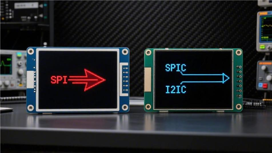
The SPI display interface requires 4 wires and can reach frequencies of 50MHz or higher, making it suitable for driving color TFT screens to smoothly play animations. The I2C interface, on the othe...
Leave a comment
This site is protected by hCaptcha and the hCaptcha Privacy Policy and Terms of Service apply.