









Character OLED Display Technology: In-Depth Analysis of Interface, Controller and Driving Methods
A character OLED module looks like a simple drop-in replacement for a character LCD, but its interface, controller and driving method impose different constraints. The controller handles font rendering and character addressing in hardware; the display itself is a passive matrix, so brightness and lifetime depend on the multiplex ratio. Getting a design right means understanding all three layers, not just the connector pinout.
What the module contains
Four functional blocks sit inside a character OLED module: the OLED glass with its row and column electrodes, a driver that sources and sinks current row by row, a controller with character generator ROM and display RAM, and an interface block that translates the host's writes into controller commands.
Because the character generator lives in ROM, the host sends only character codes and positions — not pixel data. That is the format's core advantage: a 20×4 display needs a few dozen bytes per update, not thousands. The trade is fixed fonts and fixed layouts; anything outside the character set has to be drawn as a custom glyph or abandoned in favour of a graphic module.
Interface options and what they cost
Three interface families appear in character OLED modules. The parallel 6800/8080-style bus is the fastest and the most pin-hungry, and it maps closely onto the legacy character LCD timing that many older designs already have. SPI reduces the pin count to a handful at the cost of bandwidth and a slightly more involved write sequence. I²C is the most economical in pins and is adequate for character displays that update slowly.
The interface choice interacts with the controller's timing requirements rather than with the display's. A parallel bus lets the host push a full-screen update in one burst; SPI and I²C serialise it, so the visible refresh depends on the bus clock. For an interface with a blinking cursor and changing numbers, either works. For scrolling text, the bus becomes the limiting factor.
Driving method decides brightness and life
A character OLED is a passive matrix: the driver selects one row at a time and drives the columns with the current that row's characters require. With N rows, each row is on for one Nth of the frame, so the instantaneous current must be much higher than the average the eye perceives.
Two consequences follow. Brightness is bounded by what the driver can source during a row's time slot, and lifetime is bounded by the peak current the organic material tolerates. A module driven at a high multiplex ratio with high brightness therefore ages faster than the same module run dimmer — a relationship worth remembering when a product needs long service life.
Custom glyphs and the CGRAM budget
Most character controllers reserve a small block of character-generator RAM for user-defined glyphs — typically eight patterns of five by eight pixels. That budget is the difference between a standard interface and one that needs a graphic module: unit symbols, battery icons, arrows, non-Latin characters and branding marks all compete for the same few slots.
Two practical notes. The glyph bitmaps are defined by the host at runtime, which means the interface's visual language can change with firmware rather than with a new part number. And the number of glyphs is fixed by the controller, not by the display, so an interface that needs a dozen custom symbols has to choose between multiplexing glyphs (redrawing them as content changes) and moving to a graphic module.
Power-up sequence and initialisation
An OLED controller needs a defined initialisation sequence before it will display anything: display off, clock and multiplex settings, contrast, segment remap and COM scan direction, then display on. Getting the order wrong produces a blank display or a mirrored image, and because the sequence lives in firmware it is often copied between projects along with the mistakes.
Two settings deserve particular attention. The multiplex ratio must match the panel's row count, or brightness and lifetime are both wrong. And the COM scan direction and segment remap must match the module's physical wiring; a mismatch mirrors the content horizontally or vertically rather than failing outright, which makes it easy to miss during bring-up.
Contrast, dimming and content
OLED contrast comes from switching pixels off rather than blocking a backlight, so the black level is genuinely dark and the perceived contrast holds up in dim rooms. In bright ambient light, however, the reflection from the cover glass dominates, and the perceived contrast falls regardless of the panel's own ratio — the same reflection problem a transmissive display has.
Dimming is handled either by the controller's brightness command, where available, or by reducing the drive current. Reducing current is the more efficient route for battery-powered products, since the display's own consumption falls with it rather than being absorbed elsewhere.
What to check before choosing one
- Character set and font. Confirm the ROM covers the languages and symbols the interface needs; custom glyphs need spare CGRAM.
- Controller and RAM size. A controller with its own display RAM lets the host update only changed characters.
- Multiplex ratio and lifetime. Ask for lifetime at the brightness and duty the product will use.
- Interface timing. Verify the bus clock can deliver the refresh the interface requires.
- Luminance and uniformity figures with their measurement basis, standardised in ISO 9241-307[1].
Character OLED modules are listed in the character OLED collection; graphic formats in the same technology are under graphic OLED displays, and backlit character LCDs as a comparison point under character LCD.

A character OLED module combines a passive-matrix panel with a character controller, which fixes both the update path and the brightness-versus-lifetime trade. Confirm the character set, the controller's RAM, the interface timing and the lifetime at your operating duty cycle before designing one in.
References
- ISO 9241-307:2008 — Ergonomics of human-system interaction — Part 307: Analysis and compliance test methods for electronic visual displays. International Organization for Standardization. https://www.iso.org/standard/40102.html
Read more
2025’s character OLED guides highlight self-emissive tech (1000:1 contrast, μs response), used in industrial dashboards/smart home panels. Select via.
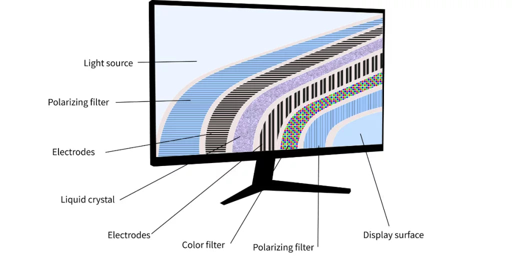
PMOLED uses row-column addressing (no TFTs), driving pixels via AC pulses (~10V). Found in 0.96” 96x64 displays (150cd/m²), powering.
Leave a comment
This site is protected by hCaptcha and the hCaptcha Privacy Policy and Terms of Service apply.