



Custom Micro OLED Display Manufacturer Selection Guide | AR Glasses, EVF, Near-Eye Integration
Select a custom Micro OLED supplier by starting at the eye, not at the panel datasheet. Field of view, pixel density after magnification, luminance after optical losses and thermal derating decide whether a part can do the job; mask ownership, driver support and test evidence decide whether it can do it repeatedly. Shortlist two or three sources and validate with samples before committing to tooling.
Start at the eye
Near-eye systems lose most of their light between the panel and the pupil. A combiner, a birdbath cube, a waveguide or a freeform prism each impose their own throughput, and the number that matters is luminance at the eye.
Build a simple optical budget: panel luminance, multiplied by optical throughput, multiplied by any dimming applied for uniformity or eye safety. If the result is below what the scene requires, no amount of firmware fixes it.
Do the budget at the worst case, which is usually a bright outdoor scene or a lit operating theatre. Indoor demonstrations flatter every panel.
Resolution, field of view and angular density
Angular resolution is pixels per degree, set by the panel's pixel count divided by the field of view it is spread across. Widening the field of view at fixed pixel count lowers angular density, which is why a wide-angle design needs a denser panel than a narrow one.
Choose the field of view from the task before choosing the panel. A camera viewfinder, a surgical overlay and a waveguide heads-up display have very different requirements, and a specification written around a favourite panel usually ends with a compromise on both.
Check the pixel pitch against the optics as well. A panel that out-resolves the lens wastes cost, and optics that out-resolve the panel show individual pixels at the edge of the field.
Brightness and thermal derating
Micro OLED luminance figures are quoted at a duty cycle and a temperature, and both change inside a product. Sealed near-eye enclosures run warm, and OLED efficiency generally falls as temperature rises, so the brightness available at the operating point is below the datasheet peak.
Ask for a derating curve rather than a single number, and ask what happens to lifetime at the brightness you actually need. High brightness and long life pull in opposite directions on the same emitter, and the trade is made in the current density.
Heat is also a comfort issue. A display that warms the brow at high brightness is a product problem even when the panel survives it.
Interface and bandwidth
MIPI DSI is the usual choice for near-eye panels: few lanes, low signal swing, good power efficiency. Embedded DisplayPort suits longer board-to-panel runs and is easier to route through a hinge or a helmet, at some cost in power and electromagnetic-compatibility effort.
Size the link from resolution, refresh rate, colour depth and blanking, then add margin. A link designed exactly at the limit will fail on the first firmware change that adds a few extra blanking lines.
Confirm that the supplier's reference design uses the interface you intend to build. A panel validated only through the supplier's own bridge board is a schedule risk, not a starting point.
Lock the driver early
The driver IC determines gamma, dimming, power sequencing and the shape of the initialization table. Changing it after the optical engine is designed forces a board respin and a fresh calibration, so it belongs in the first design review rather than the third.
Confirm that the driver supports the dimming range you need without visible flicker, that its gamma tables can be rewritten in production, and that register settings are documented rather than delivered as a binary blob.
Ask who writes the initialization code and who owns it. A supplier that provides the code also controls it, which is acceptable until you need to change something under time pressure.
Samples and stress testing
Order enough units to see a distribution, not one good sample. Brightness, colour and uniformity vary across a wafer and across lots, and the outliers are what generate field returns.
Test optically for uniformity and colour shift across the field, electrically for power and standby, environmentally for thermal shock and damp heat, and for life at the brightness you will ship.
A panel that passes at room temperature and fails under heat and humidity usually points at driver firmware or at the seal rather than at the OLED stack. Finding that on samples is cheap; finding it in production is not.

What quality evidence to demand
Ask for test reports that name their conditions: temperature, drive current, duty cycle and the instrument used. A contrast figure measured without those conditions is not comparable between suppliers, and comparability is the whole point of a shortlist; ISO 9241-307 defines one widely used set of measurement conditions for display contrast and luminance[1].
Contrast in particular is easy to overstate, because a dark-room measurement says little about a lens assembly with stray light. Ask how the number was taken and what the effective value is inside the optical engine.
Ask how uniformity is defined, whether dead pixels are counted per panel or per million, and what the acceptance limit is. Those definitions decide whether a shipment is accepted or rejected, and they are much easier to agree before the first order.
Where a third-party laboratory report exists, read its scope. A report on a different die, a different package or a different driver does not transfer to your part.
Lead time and support
Custom microdisplay schedules are dominated by backplane wafer procurement, which does not compress much. Deposition, assembly, calibration and test add the rest. Ask for the schedule split by step so you can see which part is queue and which is engineering.
Support matters as much as the part. A field application engineer who can debug a MIPI link or a gamma table locally saves weeks; one who only forwards email does not.
Agree the change-control process before the first mask. Shape, pad layout and firmware will each change at least once, and the cost of that change should be known in advance rather than discovered on an invoice.
Matching the panel to the product
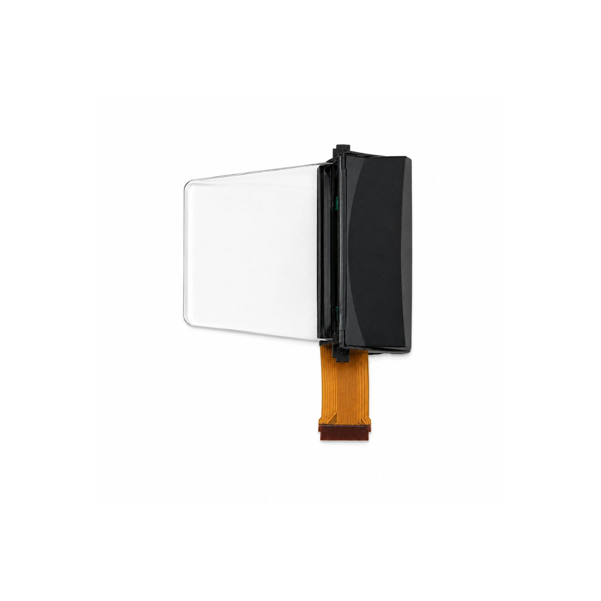
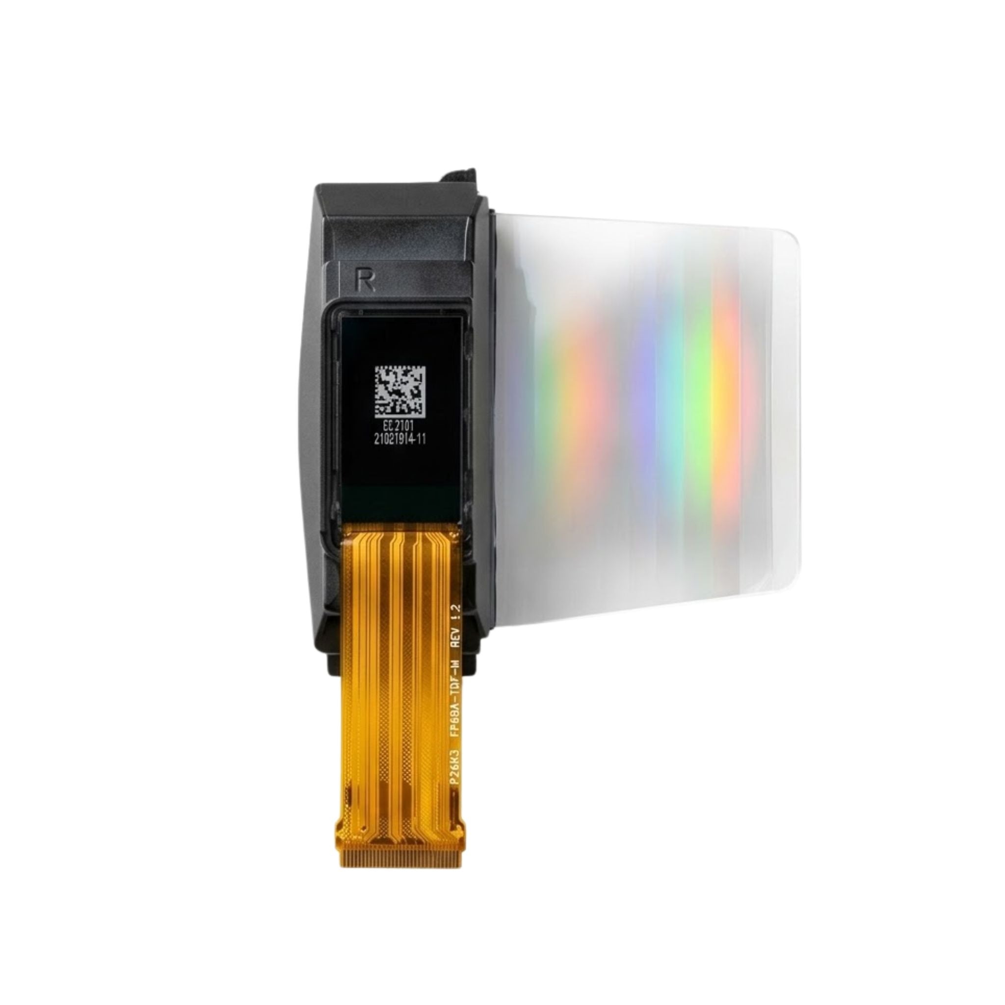
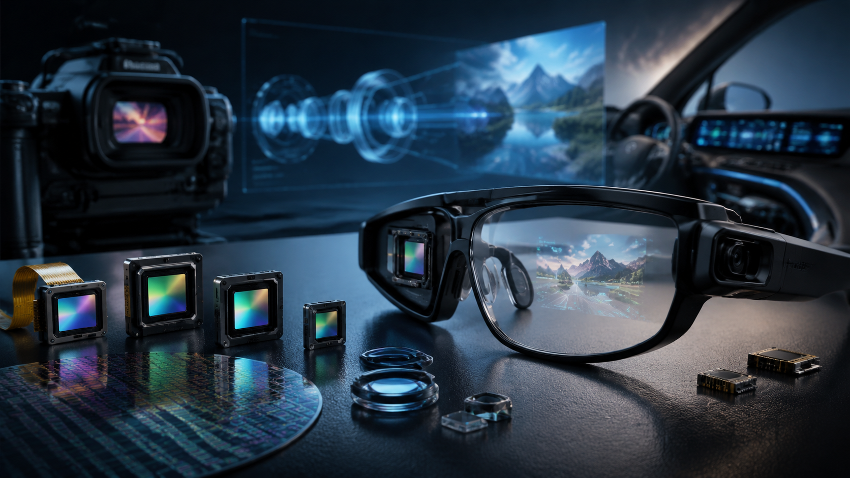
For AR glasses, the constraint is usually volume and power, so the panel, driver and flex are designed as one mechanical stack. For a viewfinder, the constraint is response and optical compatibility with an existing lens. For medical near-eye devices, the constraint is evidence: traceability, cleaning compatibility and a documented lifetime.
State the constraint at the start of the conversation. Suppliers organise their sample programmes around it, and the answers you get back will be far more useful than a generic catalogue.
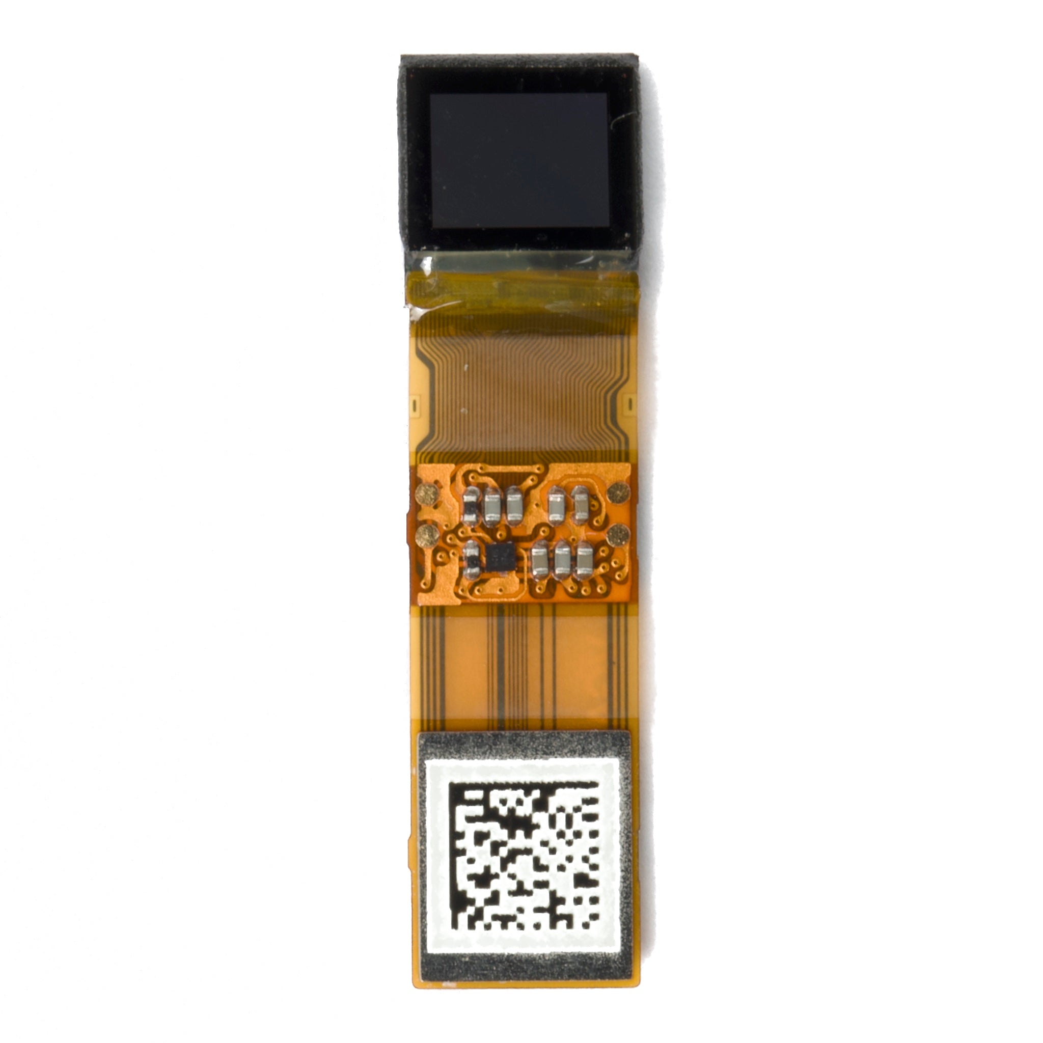
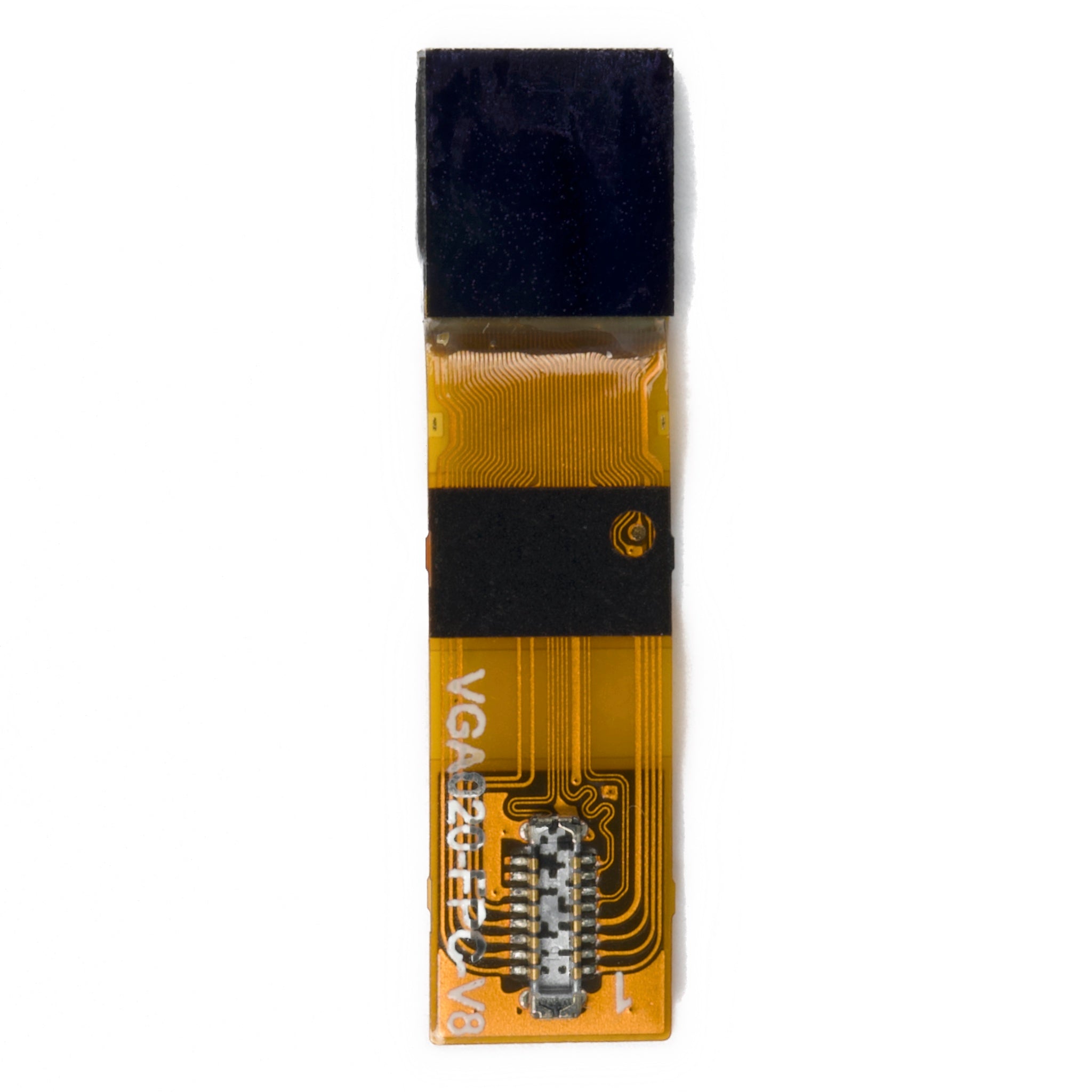
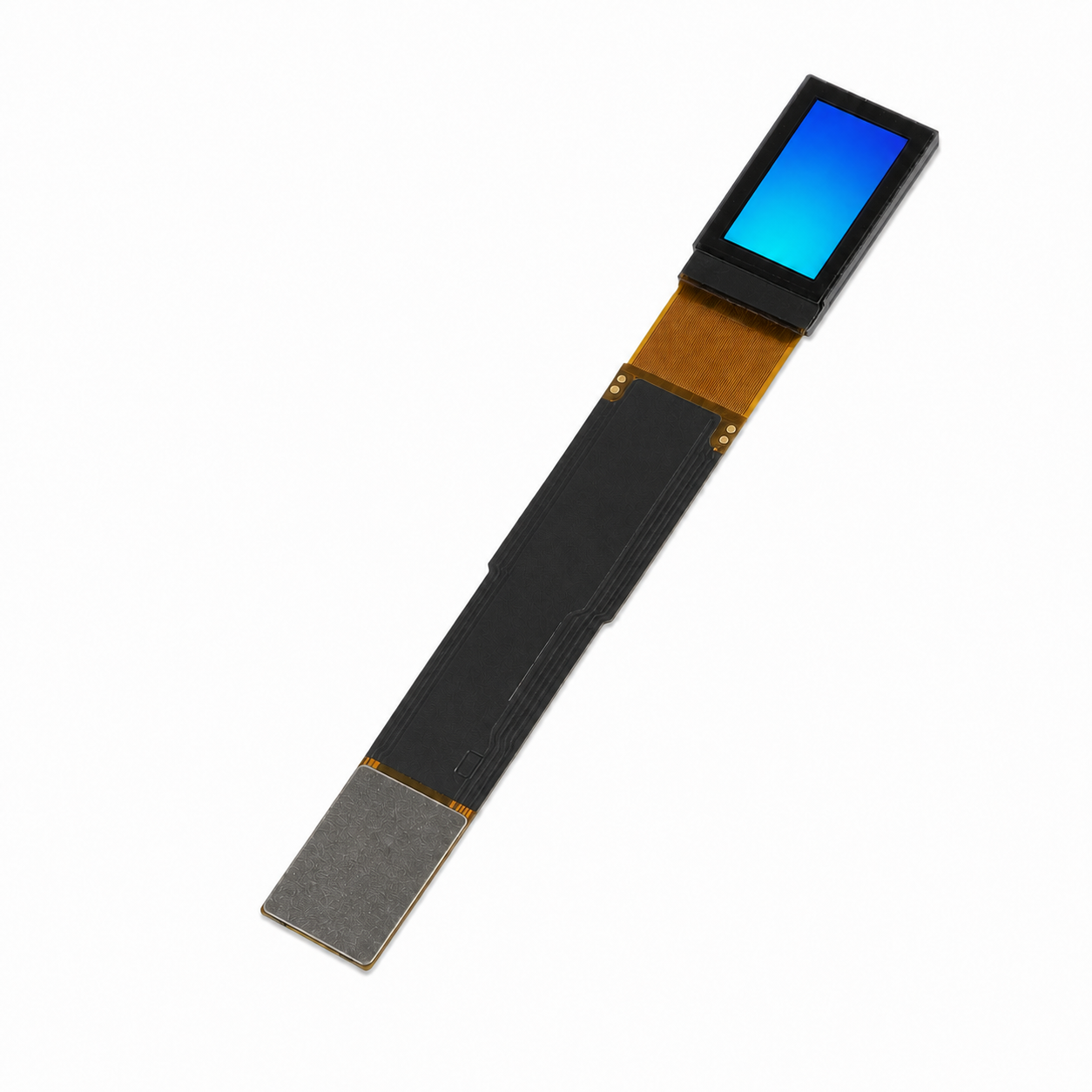
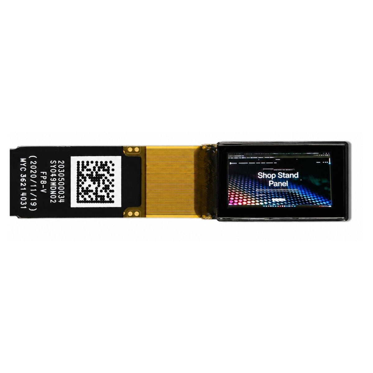
Standard Micro OLED modules are a sensible reference point before a custom run, and the AR and VR display range shows which sizes and interfaces are already available. Comparing those against an OLED module baseline also clarifies where the microdisplay premium actually sits.
Pick the supplier whose panel meets the optical budget at the operating temperature, whose driver you can own, and whose test data names its conditions. Everything else is negotiation.
References
- ISO 9241-307:2008 — Ergonomics of human-system interaction — Part 307: Analysis and compliance test methods for electronic visual displays. International Organization for Standardization. https://www.iso.org/standard/40102.html
Read more
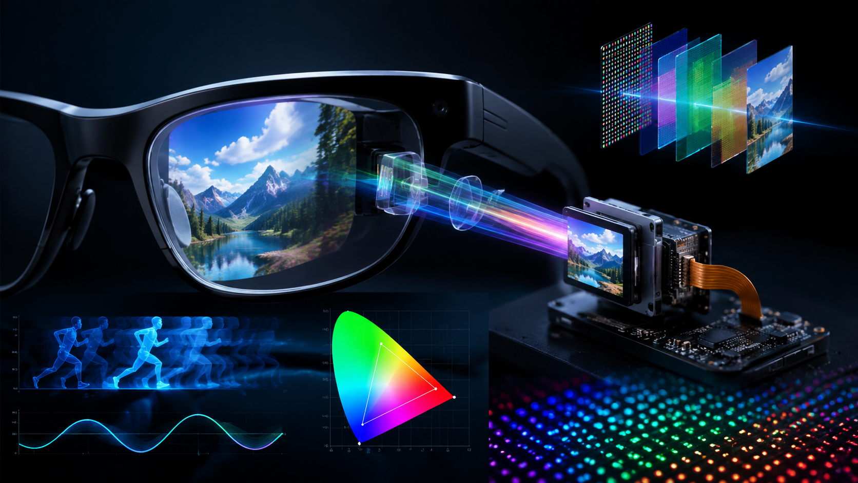
The global microdisplay market reached $1.92 billion in 2024, with Omdia projecting the near-eye display market to surge 200% year-over-year in 2026.
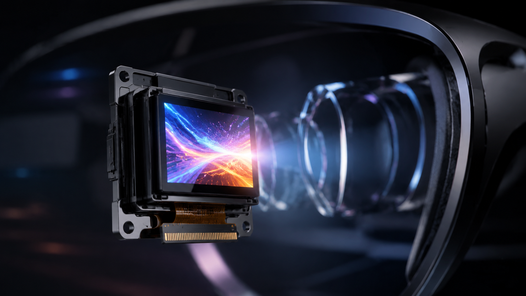
Sony ECX3 50 F pushed peak Micro OLED brightness to 10000 nits in September 2024 — a 0.44-inch module delivering 1920×1200 resolution at 5000ppi pixel.
Leave a comment
This site is protected by hCaptcha and the hCaptcha Privacy Policy and Terms of Service apply.