









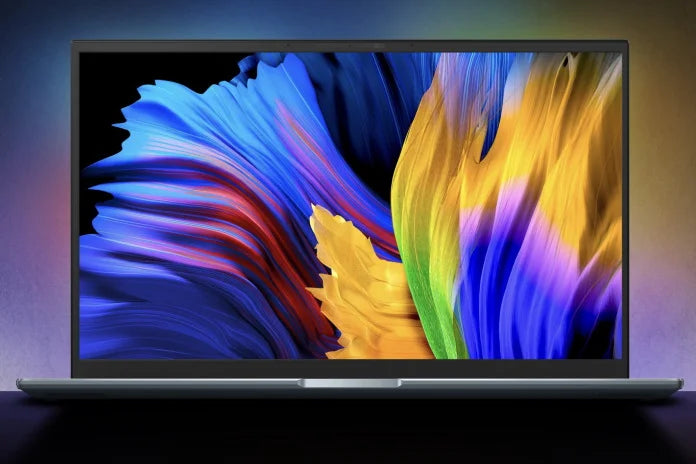
How Bright Should My Graphic OLED Module Be
The right brightness for a graphic OLED module is the lowest value that keeps the display readable in the brightest condition the product will actually meet — and that number is usually far below the module's maximum. Choosing too high costs lifetime and power; choosing too low produces field complaints. The judgment needs both the ambient light level and the content, not just a datasheet maximum.
Start from ambient light, not from the panel
Readability is a contrast problem. The eye needs a certain luminance ratio between the lit elements and the background to distinguish them, and that ratio is degraded by reflected ambient light adding to both. In a dim control room the required display luminance is modest; in an office with windows it is higher; in direct sunlight it becomes dominated by reflection rather than by the panel's output.
A practical sequence: measure the illuminance at the screen position in the brightest realistic condition, then determine whether the reflection or the emission will dominate. If the reflection dominates, raising brightness returns very little — the fix is optical (anti-glare, anti-reflective coating, bonding) rather than electrical.
Content matters as much as the environment
An interface with large, high-contrast elements remains readable at lower luminance than one with thin strokes and anti-aliased text. Two displays with identical brightness can therefore be judged differently by users, depending on what they show.
For an OLED, content also sets power: brightness is delivered per lit pixel, so a dark interface with bright text costs far less than a filled white screen at the same nominal brightness. That asymmetry makes brightness and content a coupled decision rather than independent specifications.
Brightness trades against lifetime
OLED degradation accelerates as drive current rises, and in a passive matrix the current also scales with the multiplex ratio. A module run at maximum brightness all day ages several times faster than the same module run dimmed when the environment allows.
The design implication is to make brightness adaptive rather than fixed. Where the controller exposes a brightness command, drive the display at the level the ambient light requires, and lower it at night or in a dim room. Where it does not, dimming has to come from the drive scheme, which is less flexible but still worthwhile for a product that runs continuously.
What a datasheet brightness figure does and does not tell you
A quoted luminance is usually measured on a test pattern — often all pixels lit — at a stated current and, ideally, a stated temperature. Three cautions follow. The figure applies to that pattern, not to a sparse interface. It is typically a "typical" value with production spread. And it is measured at room temperature, while brightness falls as the panel warms inside an enclosure.
The useful specification is a luminance figure at the intended drive setting, with the test pattern, the temperature and the acceptable minimum stated. That last item is what a design should actually be checked against, because readability depends on the floor rather than the average.
Turning ambient light into a target
Illuminance and display luminance are different quantities, which is why the conversion is not a single multiplication. A screen in an office might see several hundred lux of illumination; the reflected luminance it produces depends on the front surface's reflectance and how much of the environment it reflects. That reflected component is what competes with the display's own output.
A workable approximation for a specification discussion: if the reflected luminance is a meaningful fraction of the display's black level, contrast has already collapsed, and further brightness buys little. This is why the practical test is comparative rather than numerical — photograph the candidate in the real environment at fixed exposure and compare, rather than computing a target from lux.
Where a number is required for a contract, define it end to end: the illuminance condition, the surface treatment, the test pattern, the viewing angle and the acceptance criterion. Without all five, two parties can measure the same module and disagree.
Deciding the number in practice
Three steps settle it on a sample rather than in a spreadsheet. First, take the module into the brightest realistic environment and photograph it at fixed exposure with the intended interface. Second, reduce brightness step by step and find the level where the content stops being comfortably legible. Third, add margin for ageing — since brightness falls over life, the initial setting must be above the readability threshold by roughly the amount the panel will fade.
That margin is the part most often skipped. A setting that is just legible when new becomes illegible a year into service, and the failure appears as a field complaint rather than as a specification error.
What to specify
- Luminance at the intended drive setting or duty cycle, with the test pattern stated.
- Minimum rather than only typical luminance, if readability has a floor.
- Lifetime defined at that brightness, so the trade is explicit.
- Brightness derating with temperature, for sealed enclosures.
- Uniformity figure, with its measurement basis standardised in ISO 9241-307[1].
Graphic OLED modules are listed in the graphic OLED collection; character formats are in the character OLED collection, and where continuous high brightness makes OLED lifetime marginal, graphic LCD modules are the alternative to evaluate.

Set graphic OLED brightness from the brightest ambient condition the product meets, adjusted for content and with margin for ageing. Prefer adaptive dimming over a fixed maximum, and specify luminance with its test pattern, temperature and minimum value — the floor, not the average, is what decides readability.
References
- ISO 9241-307:2008 — Ergonomics of human-system interaction — Part 307: Analysis and compliance test methods for electronic visual displays. International Organization for Standardization. https://www.iso.org/standard/40102.html
Read more
For standard display modules, common sizes range from 1.3 to 2.8 inches diagonally , with popular options like 1.3-inch (128x64 pixels), 1.54-inch.
Yes, TFT LCD modules generally support touch easily: over 70% of modern TFT panels integrate pre-designed touch layers (resistive or capacitive), adding.
Leave a comment
This site is protected by hCaptcha and the hCaptcha Privacy Policy and Terms of Service apply.