

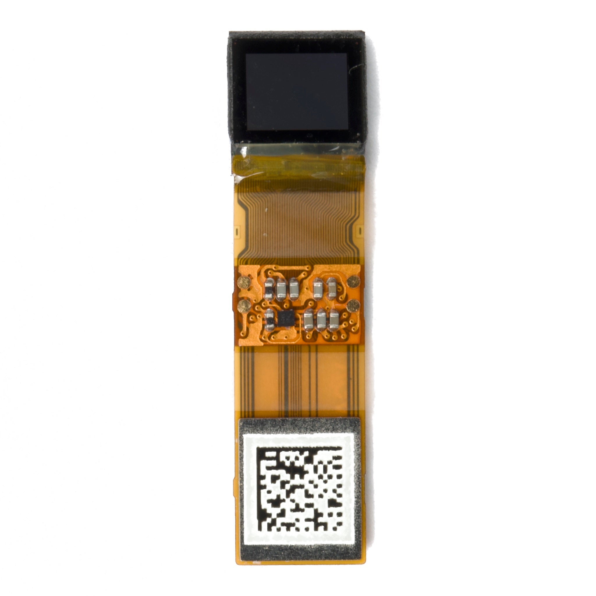
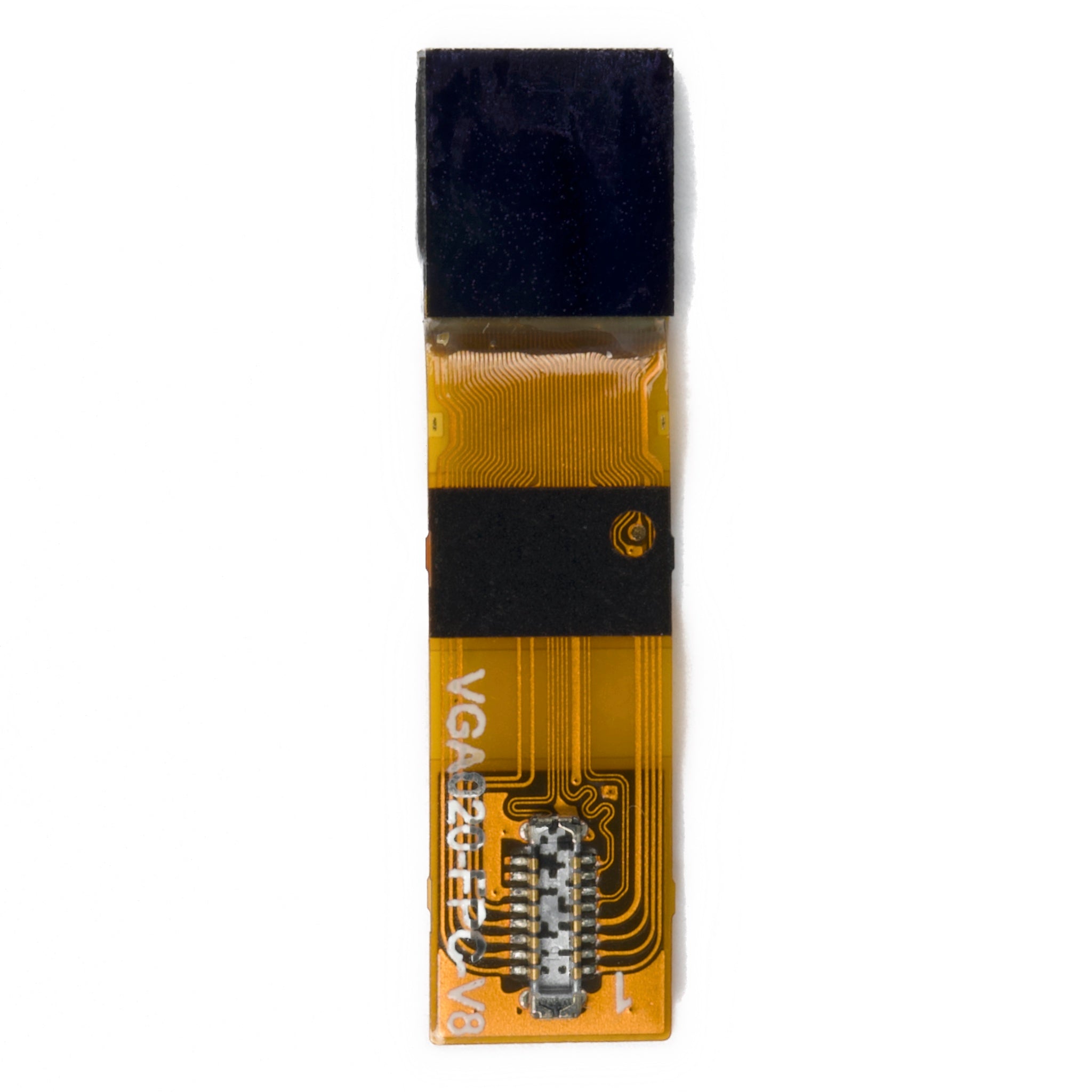
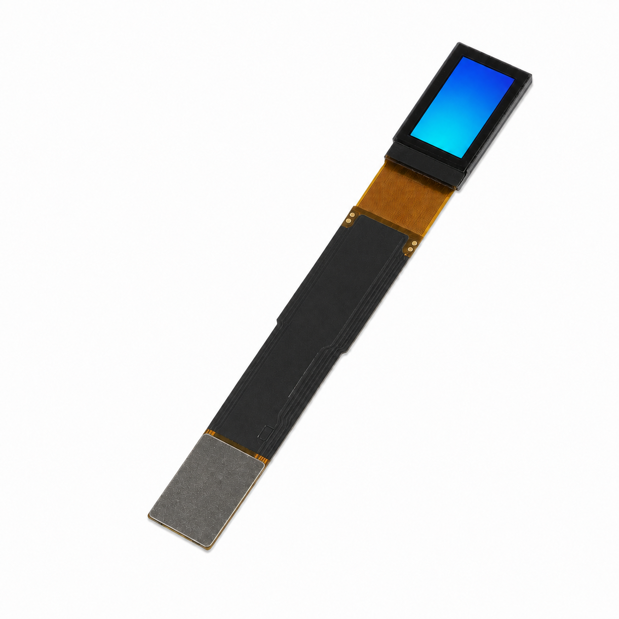
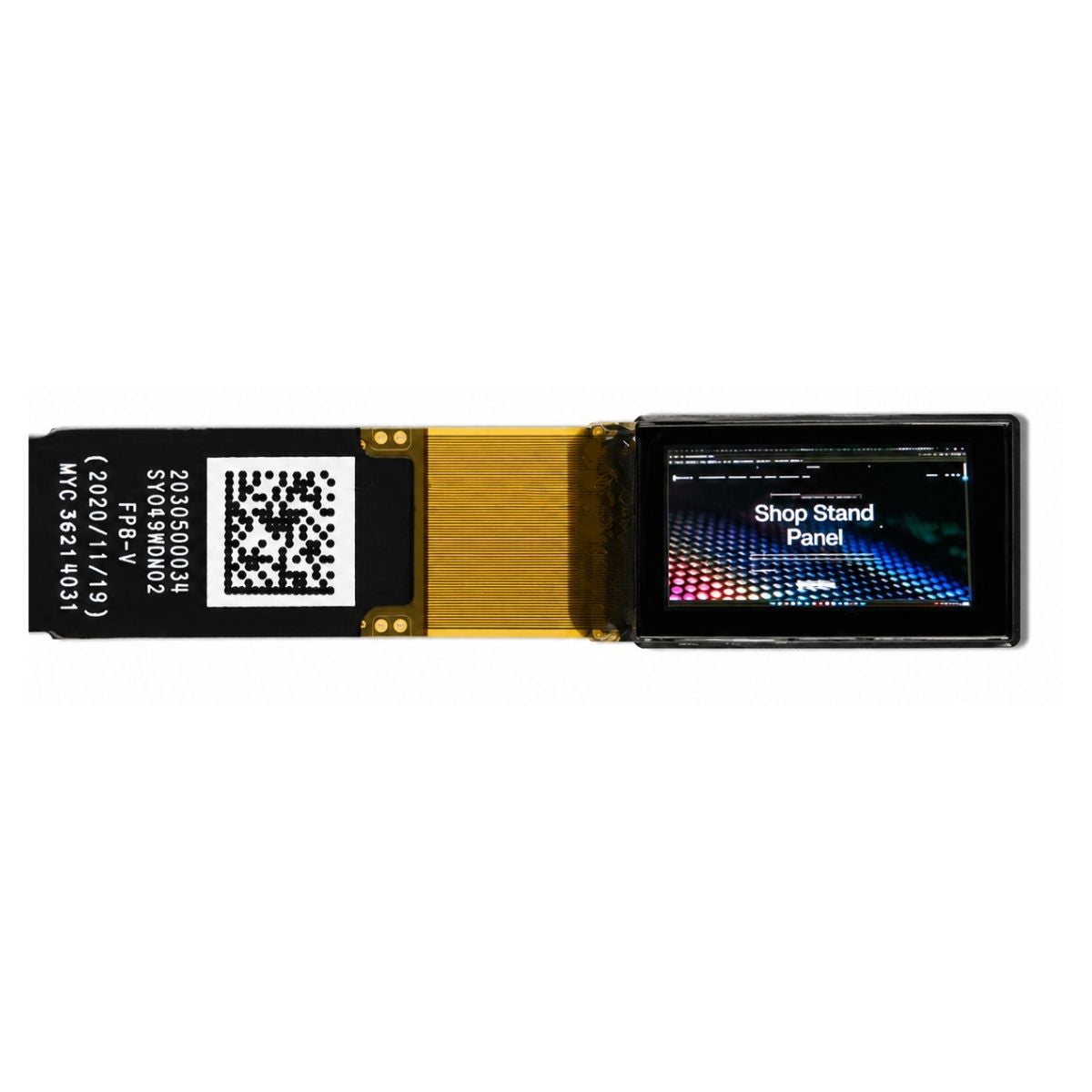
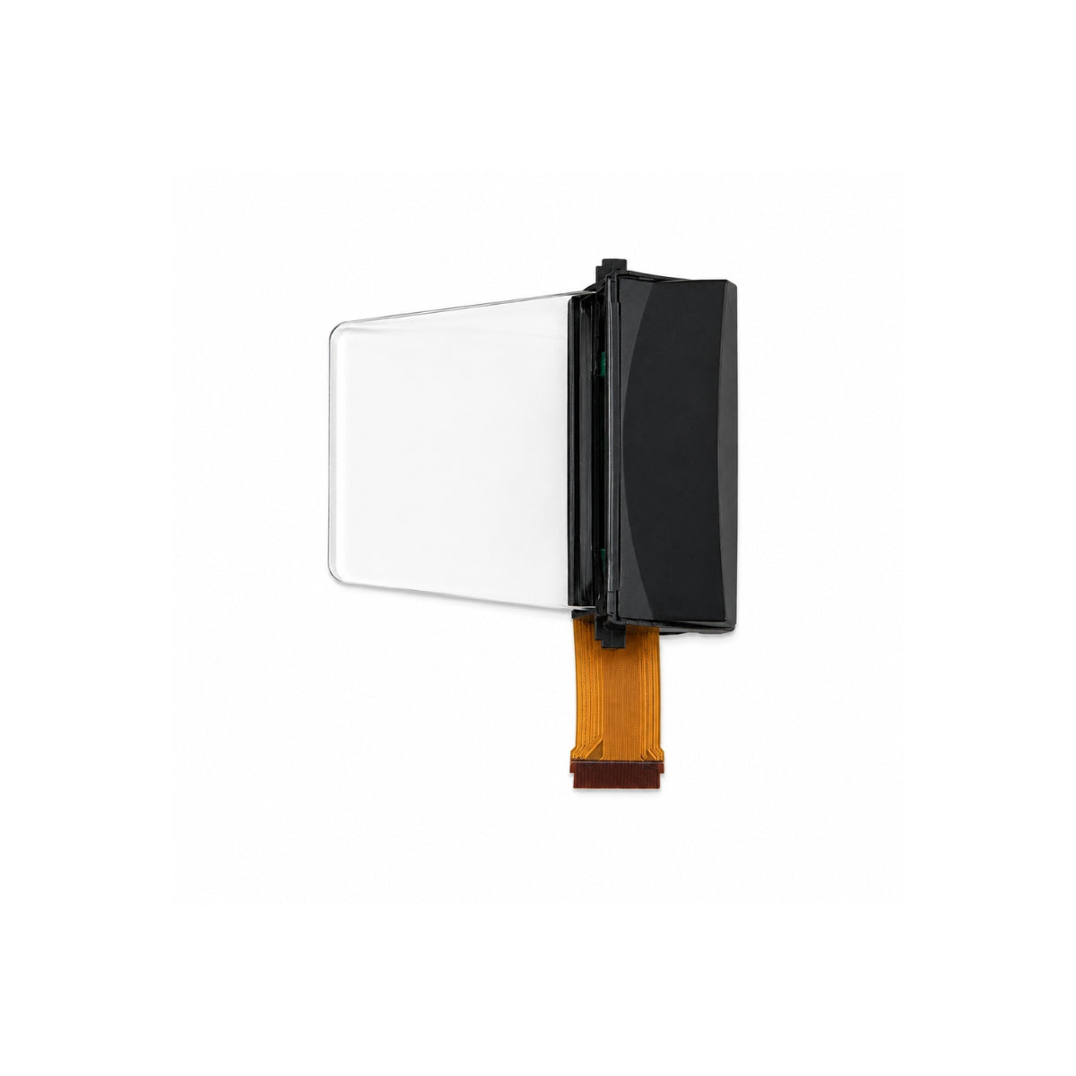
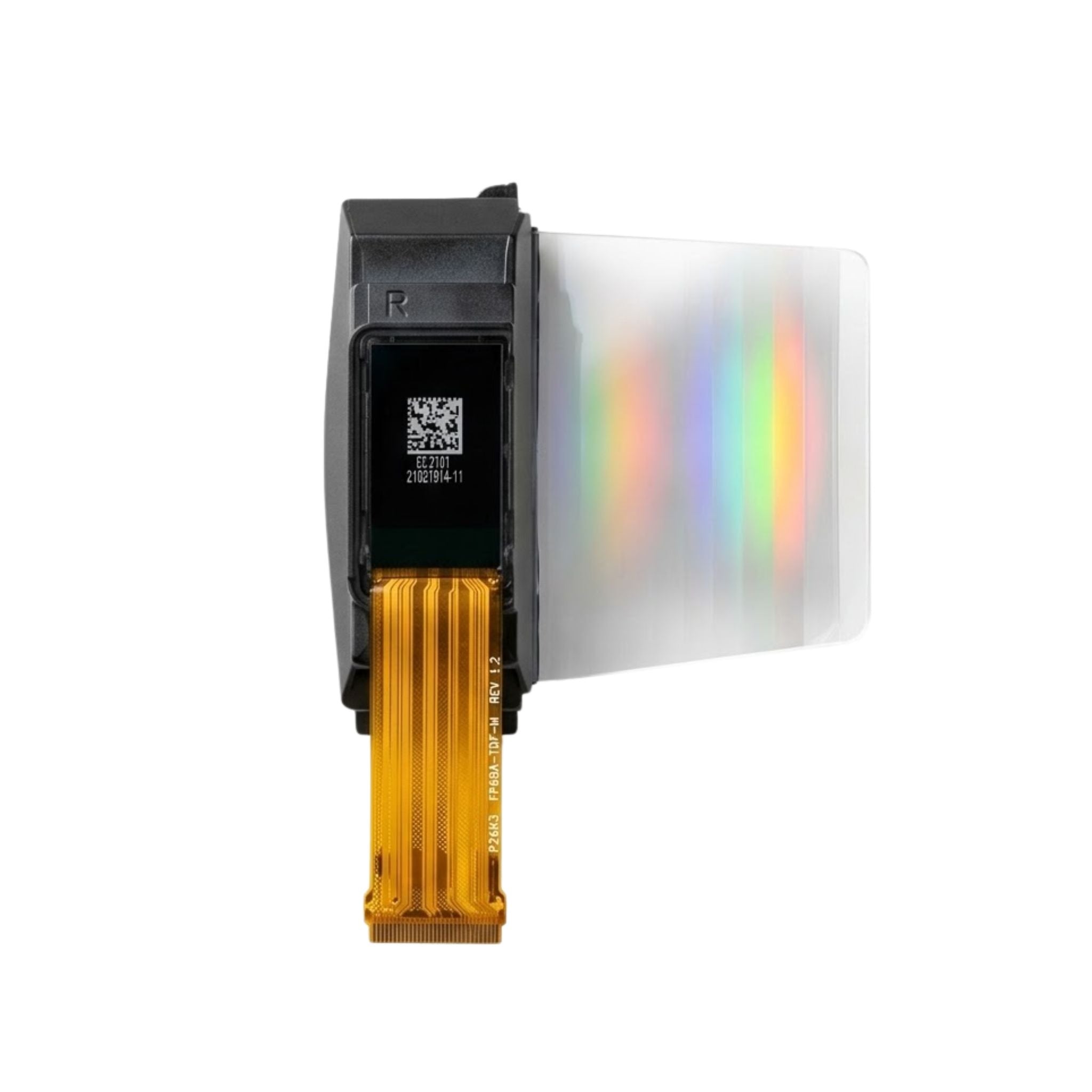


Sony Micro OLED modules are strong candidates for viewfinders and compact near-eye displays when dark-scene contrast, fine detail, and fast pixel response matter. Sony identifies camera electronic viewfinders (EVFs) as a main application and offers high-luminance models for AR and VR. Those strengths justify a shortlist, not a claim that Sony wins every comparison [1].
They are less suitable for large direct-view screens or products that cannot manage OLED aging. Outdoor see-through AR needs a model-specific brightness check, not an automatic rejection. Choose only after the complete module meets your visibility, power, temperature, interface, and lifetime requirements.
A Sony panel specification is not a finished-module guarantee. Confirm the exact panel, driver board, optics, and operating conditions before comparing numbers.
Where Sony Micro OLED Is Strong
Dark-Scene Contrast
Self-emissive pixels do not need a backlight behind dark areas. Sony lists 100,000:1 contrast among its OLED microdisplay technology characteristics [1]. This makes the technology relevant to low-light camera previews and dark-scene imagery. In the finished viewer, stray light and lens reflections can still reduce visible contrast.
Detail and Color
Sony describes an on-chip color-filter structure and pixel-compensation circuits intended to preserve viewing-angle performance and luminance uniformity as pixel sizes shrink [2]. For selection, compare active area, resolution, and pixel arrangement with the lens design. Pixel density alone does not tell you whether small text will remain readable across the field of view.
An emissive panel also removes a separate illumination block from the display architecture. That can simplify a near-eye engine, but the eyepiece, mounting, and heat path still determine its overall size.
Pixel Response
Sony lists a response time of 0.01 ms or less as a technology characteristic [1]. Do not confuse that with frame rate or motion-to-photon latency. Sensor readout, rendering, interface buffering, and emission duration also affect moving-image quality. Check the exact drive mode and test moving edges through the finished optics.
What the Published Numbers Show
The ECX350F provides a concrete example. Sony's September 2024 announcement specifies the following values for this AR-oriented panel, not for every Sony Micro OLED module [3].
| Parameter | Published value | Selection implication |
|---|---|---|
| Display size | 0.44 type; 11.235 mm diagonal | Use the mechanical drawing for package and mounting dimensions. |
| Resolution | 1,920 × 1,080 | Check text size through the intended field of view. |
| Pixel pitch | 5.1 µm | Match the lens's resolving ability and alignment tolerances. |
| Maximum frame rate | 120 fps | Confirm the supported mode and host bandwidth. |
| Video interface | MIPI DSI | Verify controller compatibility; a matching connector is not enough. |
| Maximum luminance | 10,000 cd/m² at 100% duty drive | This is panel luminance, not brightness delivered to the eye. |
| Contrast | 100,000:1 or higher | Do not carry this figure over to an ambient-lit optical assembly. |
These numbers show why “Micro OLED is only for indoor use” is too broad. They do not establish outdoor readability, continuous operating lifetime, or the performance of a third-party assembly. Request the current datasheet and its measurement conditions for the part being quoted.
Where the Trade-Offs Matter
Outdoor Visibility
In see-through AR, the displayed image competes with the real scene. Light lost in the optical path, scene transmission, and ambient illumination all matter. For XR modules for AR eyewear, specify brightness at the eye alongside field of view, eyebox, and eye relief. A larger panel-luminance number alone cannot settle the choice.
A Micro-OLED waveguide assembly combines a display engine with optics. Evaluate that complete configuration under your intended lighting, rather than comparing its eye-level output with another supplier's bare-panel figure.
Aging and Static Content
OLED output changes with use. Brightness, temperature, and content history affect aging; fixed bright symbols can create uneven wear. A status display that runs continuously therefore needs a different lifetime evaluation from an intermittently used viewfinder.
Request the supplier's lifetime definition, test temperature, drive conditions, and allowed luminance loss. Validate your actual icons and duty cycle. Dimming, sleep behavior, and pixel shifting may help where supported, but they do not replace lifetime testing or guarantee that burn-in cannot occur.
Integration and Total Cost
“Module” does not specify a standard set of included parts. A listing may mean a panel, a panel with a driver board, or a complete optical assembly. For example, the 0.49-inch MIPI Micro OLEDoS listing separates panel and HDMI-to-MIPI adapter options. Do not assume an adapter is included or that every OLEDoS listing uses a Sony panel.
Compare the complete bill of materials: panel, bridge, power supplies, optics, mechanics, thermal parts, and calibration effort. A lower panel quote can lose its advantage if it needs a different lens or unsupported bridge firmware.
How Other Display Options Compare
Use architecture to narrow the field, then compare actual modules under matched conditions. This is not a measured ranking of suppliers.
| Option | Reason to consider it | What to verify against Sony |
|---|---|---|
| Another OLED-on-silicon panel | Retains an emissive architecture. | Resolution, pixel arrangement, color, luminance conditions, lifetime, and driver support. Brand alone does not prove an advantage. |
| LCoS | A reflective panel used with a separate illumination system. | Complete-engine brightness, contrast, polarization losses, size, and power. Check whether color is field-sequential. |
| DLP with a DMD | A micromirror-based optical engine. | Illumination, controller, optics, and thermal requirements. The DMD does not determine light-source lifetime [4]. |
| Transmissive LCD | A backlit architecture worth comparing when suitable modules meet the budget. | Black level, resolution, response, backlight power, and assembled size; do not assume a universal cost advantage. |
| Micro LED | An inorganic emissive option worth evaluating for demanding brightness targets. | Full-color implementation, resolution, uniformity, drive requirements, and actual module availability. |
TI's DLP3010, for example, is a digital micromirror device used with a controller and a PMIC/LED driver, not a self-lit panel [4]. Comparing its chip specification directly with a Sony emissive panel would omit much of the system.
How to Validate a Candidate Module
Use the following as an evaluation plan, not as reported test results. Keep a record of the panel revision, adapter revision, firmware, settings, test content, and measurement conditions so another engineer can reproduce the evaluation.
Incoming Inspection
Match the label and revision to the approved datasheet and drawing. Check the FPC contact side, connector orientation, mounting references, and visible glass damage. Resolve discrepancies before applying power. Ask which viewing, cleaning, and ESD precautions apply to the exact assembly.
First Power-On
Use a current-limited supply and follow the documented power-on, reset, initialization, and shutdown sequence. Verify rails at the module connector with suitable instruments. Do not invent a generic rail order or hot-plug the assembly unless its documentation permits it.
If the image is missing or corrupted, check both the adapter and panel path. Verify the specified lane mapping, pixel format, timing, supported link rate, and control-interface settings. An HDMI bridge must generate a mode the panel accepts; successful host detection does not prove correct panel initialization.
Optical and Lifetime Checks
Use the final optics and define pass/fail limits before testing. IEC 63145-20-10:2019 covers measurement conditions and methods for optical properties of both see-through and non-see-through eyewear displays using virtual-image optics [5]. Use an agreed applicable method and suitable equipment; a visual inspection cannot substantiate a luminance or color-accuracy claim.
| Check | Conditions to record | Selection evidence |
|---|---|---|
| Visibility and detail | Ambient lighting, eye position, optical configuration, text pattern, and drive setting. | Legibility across the required eyebox and field, plus measured luminance and contrast where specified. |
| Color and uniformity | Calibration, white point, test patterns, measurement positions, and warm-up conditions. | Results across the viewing area, not just a bright center spot. |
| Motion, power, and heat | Frame rate, emission mode, video content, input power, and measurement locations. | Moving-edge behavior, end-to-end latency where needed, and temperatures within documented limits. |
| Static-content aging | Actual icons, brightness, temperature, operating hours, and baseline measurements. | Luminance and uniformity change against the agreed lifetime criterion. |
What to Confirm Before Ordering
When comparing Micro OLED module configurations, obtain the panel maker and exact part number, current datasheet, configuration drawing, driver documentation, and included-parts list. Confirm lifecycle status, change-notification arrangements, sample-to-production consistency, and the handling of nonconforming units with the supplier.
Choose Sony when the complete configuration meets your optical and electrical requirements and its documented support fits your product plan. Keep alternatives open when eye-level brightness, static-content lifetime, integration work, or total cost fails your acceptance criteria. Sony's panel strengths are a reason to evaluate it carefully, not a substitute for that evaluation.
Discuss your module requirements
Share your target eye-level brightness, field of view, host interface, mechanical limits, and quantity for a configuration discussion.
Discuss a display projectSources
- Sony Semiconductor Solutions. OLED Microdisplay. Product applications and technology characteristics, including contrast and pixel response. Accessed October 28, 2026.
- Sony Semiconductor Solutions. High-resolution Technology for OLED Microdisplays. On-chip color filters, pixel compensation, uniformity, and viewing-angle design. Accessed October 28, 2026.
- Sony Semiconductor Solutions. ECX350F 0.44-Type Full HD OLED Microdisplay announcement, September 24, 2024. Key specifications, including maximum luminance at 100% duty drive. Accessed October 28, 2026.
- Texas Instruments. DLP3010 digital micromirror device. Device architecture and associated controller and PMIC/LED driver. Accessed October 28, 2026.
- International Electrotechnical Commission. IEC 63145-20-10:2019. Public scope of fundamental optical measurement methods for eyewear displays. Accessed October 28, 2026.
Leave a comment
This site is protected by hCaptcha and the hCaptcha Privacy Policy and Terms of Service apply.