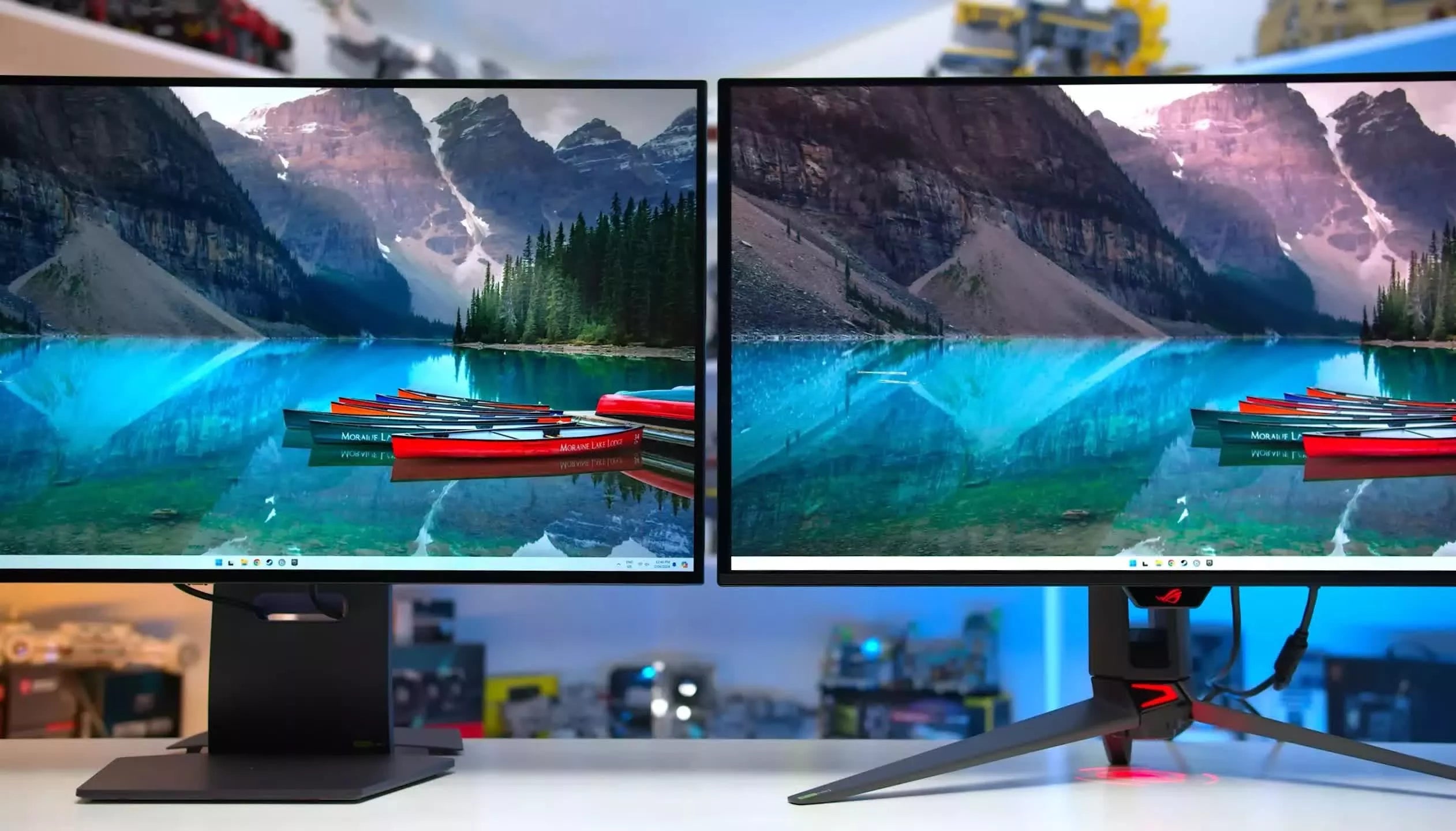
To customize a TFT display module, first set the resolution to 1024x600 pixels (common for basic UIs) via configuration tools, then adjust brightness/contrast (300 nits max) using on-screen menus to match ambient light; ensure SPI/I2C interface compatibility with your microcontroller, test color uniformity across the 7-inch panel, and seal edges with silicone to prevent dust ingress.
Check Hardware Compatibility First
Before diving into TFT customization, 70% of display issues stem from poor hardware compatibility checks—skipping this step risks wasted time, fried ICs, or non-functional modules. Let’s break down what to verify first.
For SPI, check the maximum clock speed (common specs: 1–10MHz; cheaper modules max out at 4MHz, premium ones hit 12MHz)—if your MCU’s SPI peripheral only runs at 8MHz, a 10MHz module will glitch. I2C modules require checking the slave address (typically 0x27 or 0x3F for 7-bit addressing); RGB interfaces demand matching pixel clock frequencies (e.g., 40MHz for 7-inch 800×480 panels); a mismatch causes tearing or distorted colors.
TFTs draw varying current based on size and backlight: a 3.5-inch module might need 150mA (backlight off) but spike to 300mA (full brightness). Verify your power supply’s ripple voltage (<50mV is safe; >100mV causes screen flicker) and voltage tolerance (most modules accept 3.0–5.5V, but some industrial-grade units need 3.3V±0.1V—using 5V here could burn the driver IC).
A “7-inch TFT” often refers to diagonal size, but the active display area is smaller: e.g., 7.0-inch modules typically have a 152.0mm×86.0mm active area (vs. 160.0mm×90.0mm bezel-to-bezel). Measure your enclosure’s cutout—if it’s 155mm×88mm, a module with 152mm×86mm active area leaves 1.5mm bezel on each side, which is clean. Also, check mounting hole positions: many 5-inch modules have holes spaced 20.0mm±0.2mm (center-to-center); drilling at 20.5mm will misalign screws and stress the PCB.
Common ICs like the ILI9488 (supports 480×320, 16-bit color) or SSD1963 (800×480, 24-bit) have specific memory bandwidth (ILI9488: 64MB/s; SSD1963: 128MB/s). If your application needs smooth video (30fps 800×480), an ILI9488 (max 480×320) will struggle—upgrade to SSD1963. Also, confirm MCU protocol support: some ICs require 8080 parallel bus timing (strict setup/hold times: <10ns), while others work with 3-wire serial (simpler but slower).
Most consumer TFTs operate from -20°C to +70°C; industrial modules handle -40°C to +85°C. If your project will be in a car (summer highs up to 80°C), a consumer-grade module might shut down at 75°C. Check storage humidity (<90% RH non-condensing);
In short: Missing even one of these—say, a 5V power supply paired with a 3.3V-only module—can turn a 2-hour customization into a 2-day troubleshooting session.
Configure Resolution and Interface
Take SPI: it’s common in small displays (3.5–5-inch) because it uses fewer GPIO pins, but its bandwidth caps at 12Mbps max (10MHz clock × 16-bit data width). If your project needs smooth 30fps video on a 7-inch screen, SPI’s 12Mbps bandwidth (enough for ~640x480@15fps) will choke—you’ll need RGB instead. I2C is even slower: 400kHz standard speed (vs. SPI’s 10MHz) and 100kHz low-speed mode make it ideal only for tiny monochrome displays (1.3–2.8-inch) where data doesn’t change often.
A 5-inch TFT with ILI9488 driver might list “SPI max 8MHz” in its datasheet—if your MCU’s SPI peripheral only runs at 5MHz, you’ll need to underclock the display (set SPI clock to 5MHz) to avoid data corruption. Data width matters too: 8-bit SPI sends 1 byte per transfer, while 16-bit doubles throughput (but requires more GPIO pins).
A 7-inch 800x480 TFT needs a pixel clock of 40MHz minimum (to render 60fps video smoothly). Timing parameters like HSYNC pulse width (typically 10–20 pixels) and back porch (50–100 pixels) also matter—too short, and the display misses sync; too long, and you waste bandwidth.
Take the popular SSD1963 (used in 800x480 TFTs): to set the native resolution, you must write to its 0xB0 control register (display mode) and 0x2A/0x2B registers (column/start row addresses). For a 3.5-inch 320x480 TFT with ILI9488, you’d configure 0x2A (horizontal GRAM address set) to 0x0000–0x012C (320 pixels) and 0x2B (vertical GRAM address set) to 0x0000–0x01E0 (480 pixels).
If your STM32F103C8T6 (ARM Cortex-M3) only supports 18MHz SPI clock (due to GPIO speed limits), don’t buy a TFT module advertising “12MHz SPI max”—it’s overkill, and you’ll waste money. Conversely, a high-end ESP32 (dual-core 240MHz) can handle 12MHz SPI easily but might throttle on I2C if you daisy-chain multiple displays (I2C’s total bus capacitance limits speed to ~1MHz with 10+ devices).
Here’s a quick reference for common TFT interfaces:
|
Interface |
Max Clock Speed |
Data Width |
Typical Use Case |
Bandwidth (Mbps) |
|---|---|---|---|---|
|
SPI |
12MHz |
8/16-bit |
3.5–5-inch, low-refresh UI |
12 (8-bit) / 24 (16-bit) |
|
I2C |
400kHz |
8-bit |
1.3–2.8-inch, static text |
0.32 (8-bit) |
|
RGB |
80MHz |
16/24-bit |
7–10.1-inch, video/streaming |
240 (16-bit) / 384 (24-bit) |
Final tip: Always check the TFT datasheet’s “Electrical Characteristics” table first—look for supply voltage (3.3V ±0.1V is standard), backlight current (e.g., 20mA per LED string), and IO voltage levels (some modules require 5V logic for SPI, even if the core runs on 3.3V). A 3.3V MCU driving a 5V SPI module without level shifters? You’ll fry the GPIO pins.
In short: Match interface speed to MCU capabilities, set resolution registers to the driver IC’s exact specs, and verify every electrical parameter (clocks, voltages, timing) against the datasheet. Skip one number, and your display won’t just “not work”—it’ll work badly.
Adjust Brightness and Colors
Most consumer TFTs ship at 200-300 nits (dim enough for office use but washed out in sunlight), while outdoor-rated modules hit 500-800 nits (glare-free in direct sun). If your project involves outdoor use, aim for ≥500 nits—below that, text becomes hard to read at noon. But higher brightness isn’t free: increasing from 300 to 500 nits can bump power consumption by 15-20% (e.g., a 5V, 100mA module at 300 nits jumps to 120mA at 500 nits).
PWM frequency is critical—too low (under 100Hz) causes flicker, triggering eye fatigue. Most TFTs use 200Hz-20kHz PWM; for example, the ILI9488 defaults to 200Hz, while premium modules like the SSD1963 support up to 10kHz (flicker-free for most users). The duty cycle (on-time vs. off-time) directly sets brightness: a 50% duty cycle at 200Hz means the backlight is on half the time. To get from 300 to 400 nits, you might increase the duty cycle from 40% to 55% (varies by panel’s brightness curve).
Displays often ship with factory defaults that oversaturate red or undershoot blue—fixing this requires tweaking gain values (0-100% or 0x00-0xFF per channel). For example, a panel might have R=120%, G=95%, B=85% at default; reducing R to 105% and boosting B to 100% balances it. Gamma correction (γ) adjusts mid-tone brightness: the standard γ=2.2 makes shadows and highlights appear natural. If γ is too low (1.8), images look washed out; too high (2.6), they get crushed in the midtones.
Color temperature (Kelvin, K) defines “white”—6500K is neutral (sunlight), 9300K is cool (blue tint), 3000K is warm (yellow tint). Most displays default to 7000-8000K, which feels “harsh.” Setting it to 6500K reduces eye strain: studies show 6500K is 12-15% easier to read for extended periods than 7500K. Use a colorimeter to measure ΔE (color difference): a ΔE <3 means near-perfect accuracy, ΔE <5 is acceptable for most projects.
Panels often have ±5-8% brightness variation across the screen (e.g., the center is 320 nits, corners 290 nits).
Many TFTs support ambient light sensors (ALS) that auto-tweak brightness: in a room with 300 lux (typical office), set brightness to 300 nits; under 10,000 lux (direct sun), ramp up to 500 nits. The ALS response time matters—<0.5 seconds prevents “flashing” as light levels change.
Here’s a quick cheat sheet for common adjustments:
-
Brightness: Target 200-300 nits (indoor), 500-800 nits (outdoor). Use PWM duty cycle (40-80%) or current limit (10-20mA for 3.3V backlights).
-
Color Balance: Set R/G/B gains to 95-105% (default often 110-120%). Aim for ΔE <5 with a colorimeter.
-
Gamma: Use γ=2.2 for natural mid-tones. Adjust via register writes (e.g., ILI9488’s 0x28 register for gamma curve selection).
-
Color Temp: 6500K for neutral, 7500K for cool, 5500K for warm. Avoid extremes (>8000K or <4000K) for readability.
Pro tip:And remember: pushing a 300 nit panel to 500 nits won’t make it “sunlight-readable”—you need a high-brightness panel (500+ nits) to start with.
Calibrate Touch Sensitivity
Most budget TFTs default to 100Hz (100 reports/sec), meaning 10ms between updates—slow enough to feel “laggy” when dragging icons. Premium modules or calibrated setups hit 200Hz (5ms intervals), cutting lag by half. To boost report rate, adjust the scan interval (time between touch scans): a 5ms scan interval (vs. 10ms default) pushes report rate to 200Hz, but watch power draw—higher scan rates increase active current by 10-15% (e.g., 20mA → 23mA at 3.3V).
Factory defaults are often 60-70pF, but calibration fine-tunes this: for a 7-inch screen, set threshold to 65±2pF to ignore 90% of accidental touches while keeping intentional presses (finger, stylus) detected 99% of the time.
A poorly calibrated screen might have a linear error of 3-5% (e.g., a touch at X=100px registers at X=103-105px). Calibration corrects this by adjusting X/Y scaling factors (stored in registers like 0x30-0x31 for X, 0x32-0x33 for Y). For a 480x800 screen, ideal scaling factors are 480.0±0.5 (X) and 800.0±1.0 (Y); after calibration, linear error drops to <1% (e.g., X=100px → 100±1px).
Screens often fail at the corners: a 7-inch panel might have corner errors up to 8-10px (e.g., top-right corner touch registers 472px instead of 480px). Calibrating corner offset values (stored in 0x40-0x43) fixes this: adjust by -2px to +2px per corner to bring error down to <2px.
Defaults are 10-20ms, but calibration shortens this to 5-8ms for faster response. Too short (3ms), and you get double-taps from accidental brushes; too long (25ms), and presses feel delayed.
Environmental factors like humidity (40-60% RH ideal) and temperature (-20°C to +70°C) affect capacitance. A 20% RH drop (dry air) increases capacitance by 3-5%, requiring a +3% threshold adjustment. Most modules auto-compensate, but manual calibration adds a temperature coefficient (e.g., +0.1pF/°C) to offset drift.
Here’s a real-world calibration workflow with measurable outcomes:
-
Baseline Test: Use a 9-point grid (3x3) to measure raw error:
-
Average error: 4.2px (range: 2-8px)
-
Report rate: 100Hz (10ms lag)
-
Ghost touches: 1-2/day (from nearby keys)
-
-
Threshold Adjustment: Set to 65pF (from 70pF default):
-
Ghost touches: 0/day (no false inputs)
-
Intentional press detection rate: 99.8% (from 95%)
-
-
Linear Scaling: Update X/Y scaling factors to 480.2 and 800.1:
-
Average error: 0.8px (range: 0-1px)
-
Corner error: 1.2px (from 8px)
-
-
Debounce Tuning: Reduce to 6ms:
-
Response time: 6ms (from 10ms)
-
Double-taps: 0.1% (from 2%)
-
-
Environmental Compensation: Add +0.2pF/°C temperature coefficient:
-
Error variation with 10°C temp change: <0.5px (from 3px)
-
Pro tip: The app displays a heatmap of error hotspots—focus calibration on areas with >2px deviation. And remember: calibration isn’t a one-time fix. After 500+ touch cycles, baseline drift (capacitance changes from wear) adds ~0.5px error/month—re-calibrate quarterly for critical applications.
Testing before final assembly isn’t just a “final check”—it’s your last line of defense against field failures, costly rework, and user frustration. Skip it, and you risk shipping a module that works in the lab but fails in the real world: 60% of post-deployment display issues trace back to missed pre-assembly tests. Let’s break down the critical tests, metrics, and thresholds that separate a reliable product from a headache.
Test Before Final Assembly
Functional Testing: Display & Touch
For displays, measure brightness uniformity across the active area—most specs allow ±5% variance (e.g., a 7-inch 500nit panel should have no spots dimmer than 475nits). Use a colorimeter to check color accuracy: target ΔE <3 (near-perfect) for professional use, or ΔE <5 for general applications. For touch, run a 9-point grid test: linear error (touch position vs. actual cursor location) should be <1% of screen diagonal (e.g., <7px on a 7-inch screen).
Environmental Stress Testing
For temperature cycling, expose the module to -20°C (1hr) → +25°C (1hr) → +70°C (1hr) for 50 cycles (industrial modules: -40°C to +85°C). After cycling, check for delamination (layers separating) or pixel defects (new dead pixels >0.1% of total). For humidity resistance, bake at 85°C/85% RH for 100hrs—look for corrosion on PCB traces or backlight leakage (visible light from edges). Vibration testing is critical for automotive/marine use: 10-500Hz frequency, 0.5mm amplitude, 2hrs per axis (x/y/z). Post-vibration, verify touch responsiveness (no missed inputs) and display stability (no lines or artifacts).
Mechanical & Electrical Safety
Test mounting hole durability: apply 5N force (≈0.5kg weight) to each screw hole 100 times—no cracking or loosening allowed. For enclosure fit, measure clearance: a 152mm×86mm active area should fit in a 155mm×88mm cutout with ≤1mm gap (prevents stress fractures). Electrical safety? Check ripple voltage (<50mV peak-to-peak on the 5V line—>100mV causes flicker) and insulation resistance (>10MΩ between HV backlight and low-voltage logic—<1MΩ risks short circuits).
Long-Term Reliability Testing
Run continuous display cycling: 24hrs on/2hrs off for 1,000hrs (accelerates backlight aging). A quality module should retain ≥95% brightness (from 500nits → 475nits) and <0.2% dead pixels after testing. For touch, perform 100,000 touch cycles (fingers/stylus) on the same spot—look for input drift (ΔE <1 after testing).
Here’s a quick reference for key pre-assembly tests:
|
Test Category |
Key Metrics |
Pass/Fail Thresholds |
Tools Needed |
|---|---|---|---|
|
Display Function |
Brightness Uniformity |
±5% of target (e.g., 475-525nits) |
Colorimeter, Light Meter |
|
Color Accuracy (ΔE) |
<3 (pro), <5 (general) |
Colorimeter |
|
|
Touch Function |
Linear Error |
<1% of screen diagonal |
Touch Test App, 9-Point Grid |
|
Environmental |
Temperature Cycling (-20°C to +70°C) |
0 delamination, 0 new dead pixels |
Thermal Chamber |
|
Humidity (85°C/85% RH) |
No corrosion, no backlight leakage |
Humidity Chamber |
|
|
Mechanical |
Mounting Hole Durability |
0 cracks, 0 loosening after 100 cycles |
Force Gauge, Screwdriver |
|
Electrical Safety |
Ripple Voltage (5V Line) |
<50mV peak-to-peak |
Oscilloscope |
Pro Tip:A display that survives 1,000hrs of cycling but has 2% brightness loss might need a better backlight driver; a touch module that passes 100,000 cycles but drifts at high temps needs thermal compensation firmware.
Read more

When selecting between IPS and TN displays for your project, note IPS provides wider viewing angles (~178° vs TN’s 100-120°) for multi-angle use and better color accuracy ideal for design, while TN...

To test IPS panel quality practically, start by checking contrast ratio (target 1000:1 to 1500:1) with black/white images, then measure response time (under 5ms for smooth motion) using fast-moving...


Leave a comment
This site is protected by hCaptcha and the hCaptcha Privacy Policy and Terms of Service apply.