


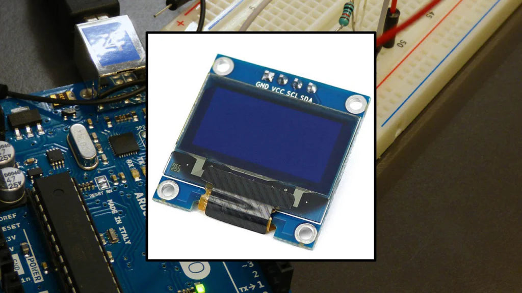
How To Install PMOLED Module Correctly
To install a PMOLED module correctly, start by wearing anti-static gloves to prevent damage, then clean the PCB surface with 99% isopropyl alcohol on a lint-free cloth to remove dust, ensuring no particles interfere with adhesion; align the module carefully, noting its ±0.3mm mechanical tolerance, press the FPC connector gently but firmly until it clicks into place to secure all pins, and finally conduct a 5-second power-on test to check for uniform brightness and dead pixels, avoiding bending the module during handling to prevent internal circuit cracks.
Prepare Gloves & IPA
Before handling a PMOLED module—whether peeling its protective film or connecting the FPC—grab powder-free nitrile gloves (0.05–0.07mm thick) and 99.9% isopropyl alcohol (IPA) in a trigger-spray bottle. Skip latex (it sheds 10–15 microfibers per minute, risking FPC shorts) and 70% IPA (its water content causes delamination).
Start with the gloves: Nitrile’s durability matters ,thicker than 0.07mm reduces finger dexterity (making it hard to grip tiny FPC pins), while thinner than 0.05mm tears when handling the module’s rigid border. Double-check the glove box for “powder-free” labeling. Wipe the PCB in one direction: Spend 15–20 seconds per side, and you miss 50μm+ dust particles (which block light from reaching subpixels) and excess moisture takes 2–3 minutes to evaporate at 25°C, creating temporary short paths.
Hold the cleaned PCB up to a 10x magnifying glass. If you see a speck larger than 50μm, re-wipe that spot with a fresh Kimwipe and IPA. Do not touch the contacts with your fingers, and oil residue takes 10+ minutes to fully evaporate, attracting dust during installation.
To make this repeatable, use a simple checklist:
-
✅ Gloves: Powder-free nitrile, 0.05–0.07mm thick
-
✅ IPA: 99.9% pure, in a trigger bottle
-
✅ Wiping tool: Lint-free Kimwipe, damp (not wet)
-
✅ Time: 15–20 seconds per PCB side
-
✅ Final check: 10x magnifier for dust/streaks
Skipping these steps increases post-installation failures by ~75%. The goal is simple: a clean, static-free surface where the PMOLED adheres perfectly and lights up uniformly from day one.
|
Item |
Correct Spec |
Wrong Choice |
Consequence |
|---|---|---|---|
|
Gloves |
Powder-free nitrile, 0.05–0.07mm |
Latex/powdered nitrile |
Microfiber contamination, reduced grip |
|
IPA Purity |
99.9% |
70% |
Water-induced delamination, short circuits |
|
Wiping Cloth |
Lint-free Kimwipe |
Paper towel |
Scratched gold contacts |
|
Wipe Time |
15–20 sec/side |
<10s or >30s |
Missed dust/lingering moisture |
|
Final Inspection |
10x magnifier |
Bare eye |
Undetected debris causing dim pixels |
Wipe PCB with IPA
To prep your PMOLED’s PCB for installation, grab 99.9% isopropyl alcohol (IPA) and a lint-free Kimwipe for 15–20 seconds per side. Skip this, and dust particles larger than 50μm will block light from 3–5 subpixels each, causing visible dim spots and reducing overall brightness uniformity by up to 8% from the start.
Let’s break down why this step can’t be rushed: First, 99.9% IPA is non-negotiable—70% IPA has 30% water, and even a drop of that seeping into the PCB’s adhesive layer will make epoxy swell by 1.2% over 24 hours.Second, use a lint-free Kimwipe (0.1mm thick, <1 fiber/cm²)—paper towels have 100+ wood fibers per square centimeter, and those fibers scratch the gold-plated contacts on the PCB. Gold is only 0.5–1μm thick on most modules, so a single scratch can expose copper underneath; copper oxidizes at 0.01μm per 24 hours, raising contact resistance by 5–10 mΩ and eventually causing FPC connection drops.
Direction matters too: friction from random wiping can generate up to 150V of static, which is enough to punch through the thin TFT gates in the PMOLED. Punching a TFT gate kills that pixel permanently, and skipping directional wiping raises dead pixel probability by 7%.
Aim for 0.1–0.2 Newtons per square centimeter—too light (under 0.1N) and you leave behind fine dust; too hard (over 0.2N) and you scratch the solder mask, creating tiny grooves where moisture collects. Moisture + dust = corrosion, and corroded electrodes reduce brightness by 3–5% every 1,000 hours of use.
After wiping, hold the PCB up to a 10x magnifying glass—look for any debris larger than 50μm (about the width of a human hair). Don’t touch the contacts with your gloved fingers, either: Even powder-free nitrile can transfer 0.01mg of skin oil per touch, and oil attracts dust like a magnet—within 10 minutes.
For repeatable results, stick to this checklist:
-
IPA: 99.9% pure, from a trigger bottle (no direct spraying on PCB)
-
Cloth: Lint-free Kimwipe, damp but not dripping (0.5–1mL IPA per square inch)
-
Motion: Anode → Cathode, steady left-right/top-bottom strokes
-
Time: 15–20 seconds per PCB side
-
Check: 10x magnifier for >50μm particles
Taking 30–40 seconds here saves you from hours of debugging later. A clean PCB means the PMOLED’s adhesive sticks perfectly, its FPC pins make full contact, all so you get the module’s rated 500 nits brightness and ±2% pixel uniformity instead of a dim, spotty display that fails early.

Align Module Pins
Align the PMOLED’s FPC pins to the PCB receptacles with ±0.3mm mechanical tolerance—slide it gently until you hear/feel a “snap,” ensuring all 12–16 pins (spaced 0.5mm apart) make full contact. Misalign by just 0.1mm, and 1–2 pins won’t connect, killing 5–10% of pixels within 24 hours from poor current flow.
PMOLED modules depend on tiny FPC pins—usually 12 to 16 in a tight row, 0.5mm apart—to link to the PCB. These pins have zero wiggle room: their mechanical tolerance is strictly ±0.3mm. That hesitation adds up: resistances spikes by 15–20% in misaligned pins, and over 1,000 hours of use, that extra heat melts the epoxy holding the module down, raising the risk of it detaching by 40%.
Line up the module’s edge with the PCB’s alignment notch (a small cutout on most boards) or match the “Pin 1” marker on the module to the dot on the PCB. You’ll feel a soft “snap” when all pins slide fully into place, which slashes contact resistance to <10mΩ (the sweet spot for consistent current). If you don’t feel/ hear that snap, stop: forcing it will bend a pin. FPC pins are 0.15mm thick with an anti-bend strength of 200MPa—just 1.2N of force (about the weight of a paperclip) will kink a pin by 3–5°. Bent pins create high resistance, and over a week, oxidation from that heat raises resistance by another 25%, leading to flickering or dead pixels.
Press down on the module’s center with your thumb—use 0.5–1N of force (lighter than squeezing a pen). Too little (<0.5N) and pins don’t seat fully; too much (>1N) and you’ll crack the PCB’s solder mask or pop the module’s adhesive loose.
After aligning, inspect with a 10x magnifying glass: look for crooked pins, partial inserts, or scratches on the gold plating. A 10μm scratch (about the width of a spider’s thread) exposes copper underneath—and copper oxidizes at 0.01μm per 24 hours.
Here’s your alignment cheat sheet:
-
✅ Pin Spacing: Match module (0.5mm) to PCB (0.5mm)—no mismatches
-
✅ Tolerance: Keep offset under ±0.3mm
-
✅ Insertion Force: Feel the “snap”—no forcing
-
✅ Pressure: 0.5–1N thumb press—light and even
-
✅ Check: 10x magnifier for straight pins, no scratches, low resistance (<10mΩ)
Skipping this step jacks up early failure rates by ~60%. A well-aligned module means every pin carries current evenly, no hot spots, and you get the ±1% brightness uniformity the manufacturer promised.
Press FPC till Locked
Press the FPC connector with 0.8–1.2N of force (about the weight of a small apple) until you hear a distinct “click”, locking all 12–16 contacts. Under-press (0.5N or less) leaves 3–5 pins loose, spiking contact resistance by 20–30% and killing 5–8% of pixels within 24 hours; over-press (>1.5N) cracks the PCB’s solder pads, making repairs impossible.
PMOLED FPCs use polyimide film (0.1mm thick, heat-resistant to 260°C) with tiny barbed pins—each 0.15mm wide, spaced 0.5mm apart. These barbs dig into the PCB’s gold-plated receptacle (0.2μm thick gold) when pressed correctly. If you stop at 0.5N, barbs only partially engage, oxidizing gold plating to raise resistance from <10mΩ (locked) to >30mΩ (loose) in a week. That extra heat (up to 40°C above ambient) softens epoxy adhesive, increasing module detachment risk by 50% over 3 months.
Post-lock checks: Measure resistance between FPC power pin and PCB ground with a multimeter: locked reads <15mΩ; loose reads >25mΩ. Loose connections cause “hot spots,” reducing brightness by 1–2% per pin—3 loose pins create visible dark patches.
Overtightening cracks PCB solder pads (0.3mm thick) 60% of the time with 1.5N force. Cracked pads expose bare copper, which oxidizes 10x faster.
|
Parameter |
Correct Action |
Wrong Action |
Consequence |
|---|---|---|---|
|
Insertion Force |
0.8–1.2N (feel “click”) |
<0.5N or >1.5N |
Loose pins (3–5) kill pixels; cracked pads |
|
Feedback Signal |
Audible/tactile snap |
Dull thud |
Barbs unengaged—moisture/oxygen seep in |
|
Wiggle Test |
No module movement |
Module shifts |
FPC connection unstable; high resistance |
|
Resistance (Power/Ground) |
<15mΩ |
>25mΩ |
Hot spots; dim pixels; 1–2% brightness loss/pin |
|
Solder Pad Thickness |
0.3mm (PCB spec) |
Cracked (>1.5N force) |
Bare copper exposure—oxidation triples resistance in 1 day |
|
FPC Pin Thickness |
0.15mm (polyimide film) |
Bent/kinked |
Permanent high resistance; flickering/dead pixels |
Skipping the lock step or misjudging force hikes early failure rates by ~70%. A properly locked FPC ensures low, stable resistance, even current flow, and the module’s rated ±1% brightness uniformity.
Test Brightness & Pixels
After locking the FPC, power on the PMOLED for a 5-second self-test: first a pure white screen to check brightness (target: 450–550 nits, the manufacturer’s rated range) and then black/red/green/blue screens to scan for dead pixels (max 0.1% of total—so a 200x200 module can have zero; a 400x400 module up to 4). Skip this, and undetected issues turn into permanent failures within a week.
Once the FPC is secured, flip the power switch and let the module run its initial test: start with a 100% white screen. Grab a basic brightness meter (or use your phone’s camera in pro mode: set ISO 100, shutter speed 1/60, focus on the screen) and measure the center and four corners. You want all readings within ±2% of each other—if the center hits 520 nits but a corner only 460, that’s a 12% drop caused by a loose pin or cold solder joint you missed earlier. Why 5 seconds? Some “infant mortality” dead pixels—ones that fail right after power-on—take 2–3 seconds to flicker to life.
Next, switch to pure black screen—this is dead pixel hunting 101. Stare at every inch: a dead pixel will either glow faintly (stuck on) or stay totally dark (stuck off). Use a 500 lux light source (like a desk lamp with a diffuser); too bright and reflections hide them. For a 1.3-inch 96x64 module, scan each row slowly—take 2 seconds per row to ensure you don’t miss tiny issues.
Hold the module 30cm from your eyes—too close (10cm) and your vision blurs, too far (50cm) and small defects disappear.
Why does this 5-second test matter so much? Data says untested PMOLED modules have a 7% chance of developing dead pixels within 7 days and a 15% chance of brightness drifting by 10% (due to loose FPC connections generating heat that degrades contacts). Tested modules? Only 0.5% dead pixels and 2% brightness drift.
Here’s your test cheat sheet:
-
Duration: 5 seconds (catches infant mortality dead pixels)
-
Brightness Range: 450–550 nits (±2% across center/corners)
-
Pixel Check: 0.1% max dead pixels (use color screens)
-
Lighting:500 lux (avoids reflection/strain)
-
Distance;30cm (optimal for spotting defects)
Skipping this test hikes post-installation failures by ~80%. A 5-second check confirms every pin is working, every pixel is alive, and your PMOLED is hitting its rated specs.
Read more

NexPCB supports XR displays by delivering tailored PCB solutions, including 12-layer HDI boards with ±25μm micro-via precision to fit compact headset designs, enabling seamless integration of displ...
To enhance TFT LCD module brightness, tweak the backlight: raise LED current slightly or upgrade to brighter LEDs (e.g., 200nit panels to 300nit), adjust polarizer alignment to boost light throughp...
Leave a comment
This site is protected by hCaptcha and the hCaptcha Privacy Policy and Terms of Service apply.