



Industrial TFT LCD vs OLED Module Comparison | Control Panels, Instruments, HMI Devices
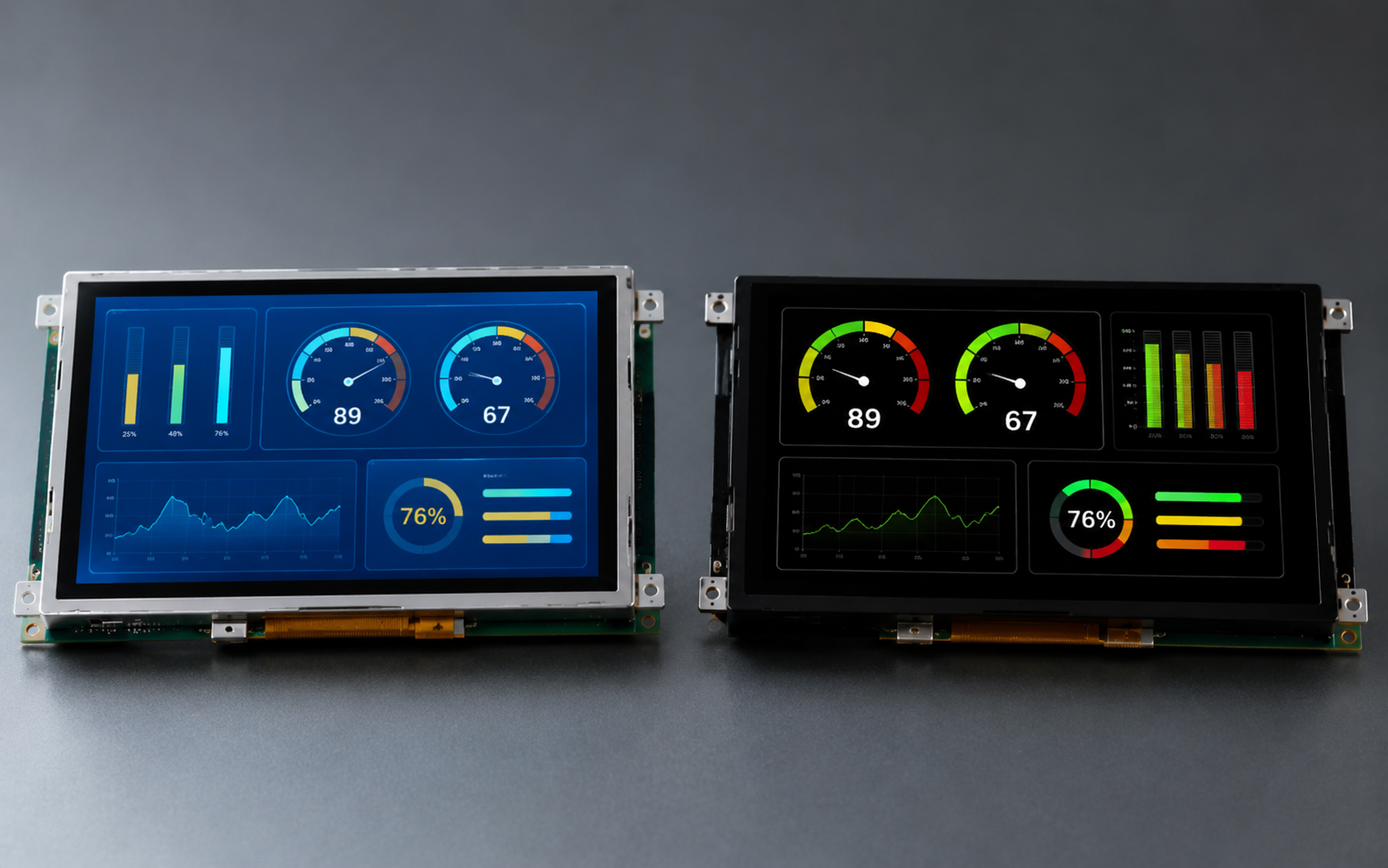
Neither TFT LCD nor OLED is the better industrial display in general. TFT LCD usually fits large panels that stay powered through a shift in bright surroundings, where a strong backlight and a mature interface ecosystem matter. OLED usually fits small, dark-themed, thin modules with short duty cycles and high contrast needs. The device environment decides, not the datasheet headline.
How the two technologies differ
A TFT LCD is transmissive. A thin-film transistor array switches each pixel, the liquid crystal layer modulates polarised light, and an LED backlight supplies the luminance. Because the light originates behind the panel, module power follows the backlight setting far more closely than it follows image content.[2]
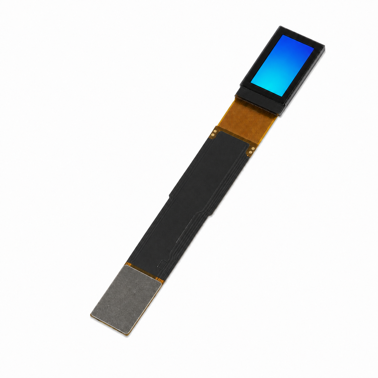
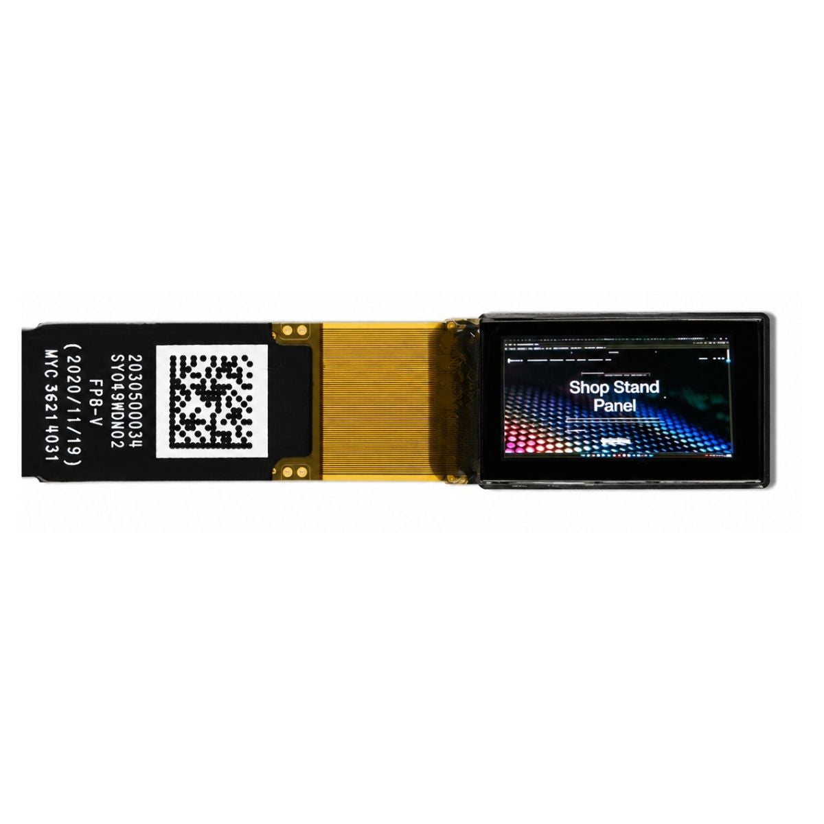
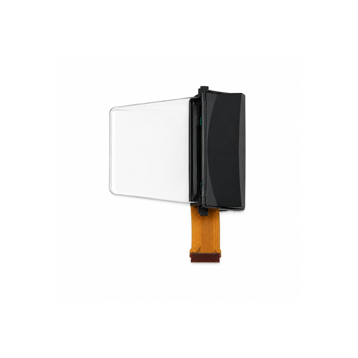
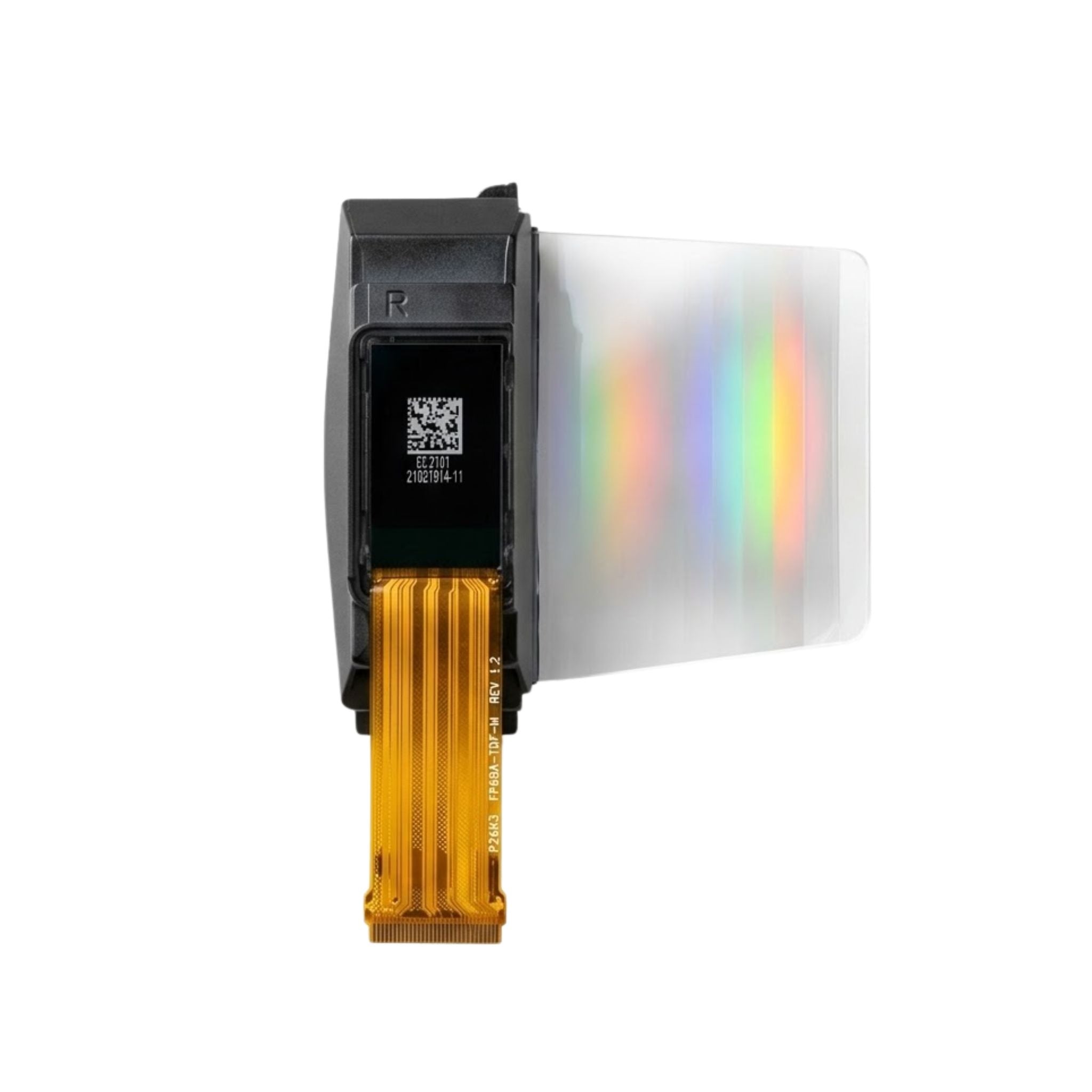
An OLED pixel emits its own light and can be switched fully off. Black areas draw little current, the stack can be thin, and contrast is set by the emitter rather than by a backlight cavity. Passive-matrix, active-matrix and micro OLED variants differ in driving scheme and size, but they share that self-emissive behaviour.
Where TFT LCD fits
Industrial HMI panels, bench instruments, access-control terminals and machine control units often stay on for a full shift and show menus, trend curves and status text on a light background. A backlight-driven module handles that content without the content-dependent ageing that self-emissive pixels show.
Size and interface coverage is the second reason. TFT glass and driver ICs span small square and round formats up to large panels, and bus options include SPI, MCU parallel, RGB, LVDS and MIPI DSI. When the enclosure is already built around a rectangular window, a standard TFT display module is usually the shortest route to a working prototype.
Where OLED fits
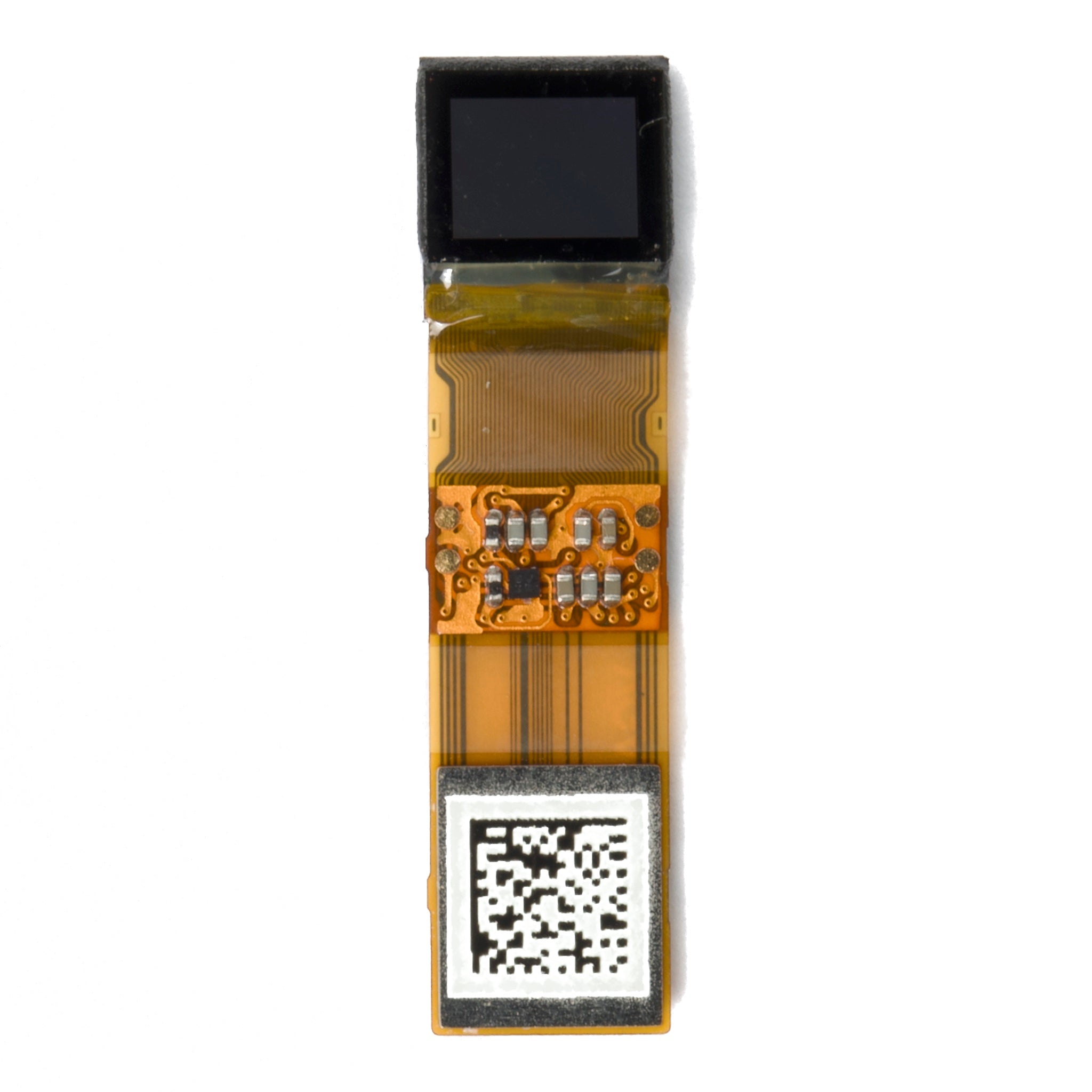
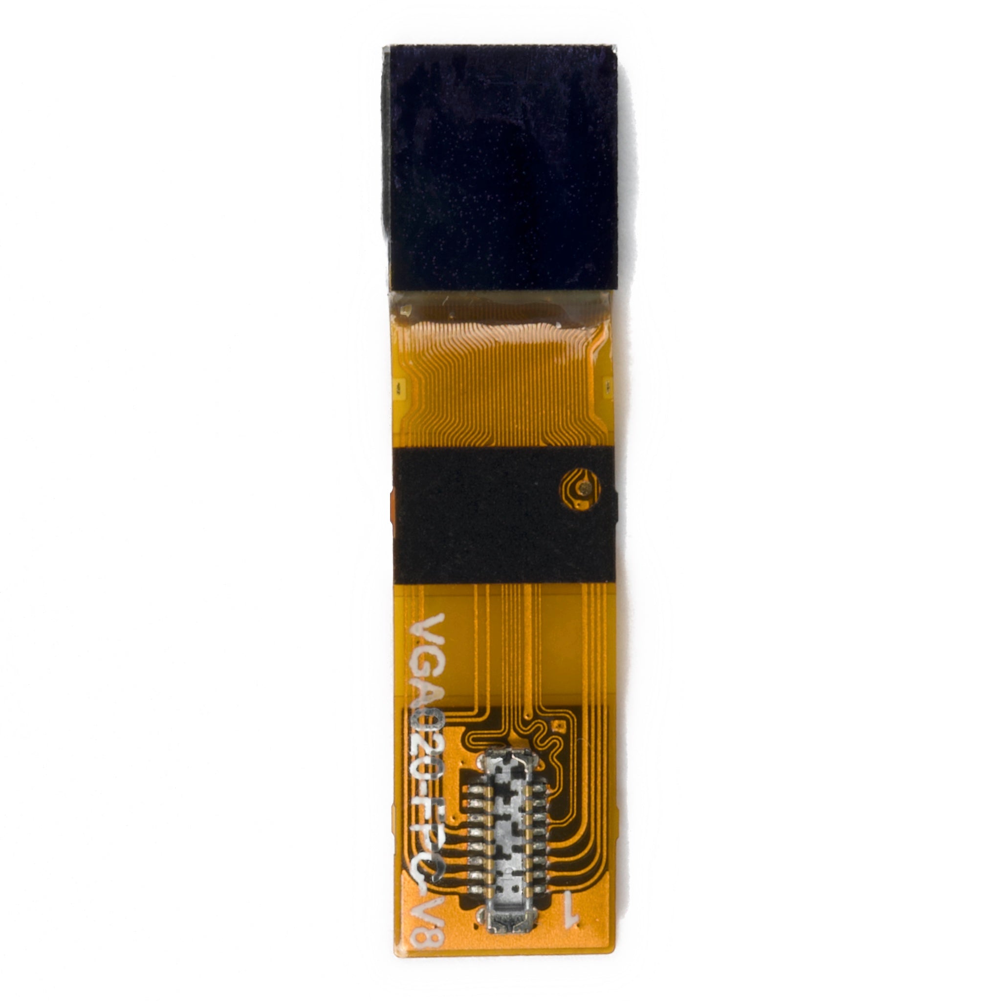
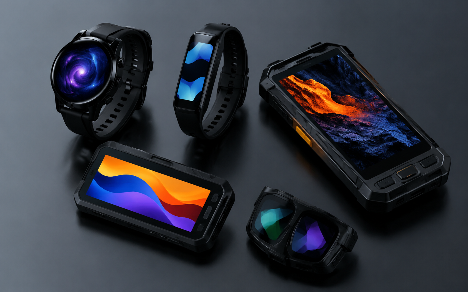
Handheld instruments, wearables, portable medical devices and premium status panels often show a small amount of information on a dark background. There an emissive module gives high contrast, a thin stack and a round or shaped outline more easily than a backlit LCD.
Monochrome graphic OLED and character OLED modules are common in that role, because the content is sparse and the screen is lit for short periods.
Brightness and readability
Readability is not one cd/m² figure. In bright surroundings the eye receives reflected light from the cover surface as well as light emitted by the display, so cover reflectance, anti-reflection coating, optical bonding, contrast ratio and stroke weight all change the outcome. A bright module behind a reflective cover can read worse than a dimmer module with bonded low-reflection glass.

For sunlit equipment the practical route is a high-brightness backlight plus optical bonding plus an AR-coated cover, followed by a measurement of the assembled stack rather than the bare panel. OLED can reach high peak luminance, but sustained high drive raises junction temperature, which feeds back into lifetime and colour shift.
Power consumption
TFT power is dominated by the backlight, so a white screen, a black screen and a menu screen draw similar current at the same brightness setting. OLED power scales with lit area and drive level, so a dark status screen draws little while a full white page can draw as much as, or more than, a comparable LCD of the same size.
The comparison only means something on the real user interface. Measure black, white, typical UI, maximum brightness and standby, and record supply voltage, temperature and firmware version with every reading.
Lifetime and image retention
LCD ageing is mainly backlight ageing plus polariser and liquid-crystal degradation, which is gradual and fairly uniform. OLED ageing is emitter degradation, and it is faster where a fixed bright element sits in one place for long periods. Permanent logos, white backgrounds behind black text and static header bars are the patterns that shorten an OLED module's useful life.
Pixel-defect acceptance should be agreed in writing rather than promised verbally. ISO 9241-307 defines defect classes and the viewing conditions under which they are counted, which gives buyer and supplier a common reference instead of an argument at goods-in.[1]
Interface and cost
Interface choice is a system decision. SPI keeps pin count low but limits refresh; an MCU parallel bus raises throughput at the cost of I/O; RGB and LVDS suit medium and large panels; MIPI DSI suits high pixel density. Confirm that the host supports the bus, that the I/O voltage matches, and that initialisation code exists before the enclosure is frozen.
Unit price is a poor proxy for cost. Add the driver and boost circuit, cover glass and lamination, tooling, certification testing, and the cost of replacing modules in the field when a panel ages faster than the product.
Validate the assembly
A module that measures well on a development board can still fail inside the enclosure. Measure luminance, contrast, uniformity and colour with the final cover glass, touch layer, bonding adhesive and firmware, at the distance and angle the operator actually works from.[1]
Three checks catch most early problems:
- Mechanical: active area against the window, flex direction, connector clearance and total stack thickness.
- Electrical: power sequence, reset timing, sleep and wake behaviour, and current at minimum supply voltage.
- Thermal: temperature rise at the hottest point after the product has run through a full working period.
Record each result with its conditions. A reading without its instrument, aperture and ambient light cannot be compared with a supplier figure later, and most disagreements at goods-in turn out to be disagreements about test conditions.
Selection checklist
Four questions settle most industrial comparisons before a model number is discussed.
- Ambient light: if the screen must be read in direct sun, plan for brightness, bonding and a low-reflection cover, whichever technology is chosen.
- Content: light backgrounds with dense text favour LCD; dark screens with sparse symbols favour OLED.
- Duty cycle: a screen that is on for a full shift with fixed elements needs a technology whose ageing is not driven by those same elements.
- Service life: match the module's rated operating time to the product warranty, and write the acceptance criteria into the purchase specification.
Industrial buyers comparing these two families often find that the panel is the cheap part and the optical stack, the enclosure and the validation are the expensive ones. Budget accordingly, and treat the industrial display range as a starting point for specification, not as a finished answer.
Neither technology is a default. Choose the display that matches the light, the content and the number of hours the product will be switched on.
References
- ISO 9241-307:2008 — Ergonomics of human-system interaction — Part 307: Analysis and compliance test methods for electronic visual displays. International Organization for Standardization. https://www.iso.org/standard/40102.html
- Hilsum, C. (2010). Flat-panel electronic displays: a triumph of physics, chemistry and engineering. Philosophical Transactions of the Royal Society A, 368(1914), 1027–1082. https://doi.org/10.1098/rsta.2009.0247
Read more
DisplayModule supplies standard AMOLED display modules and supports bulk procurement, custom display integration, FPC modification, cover glass.
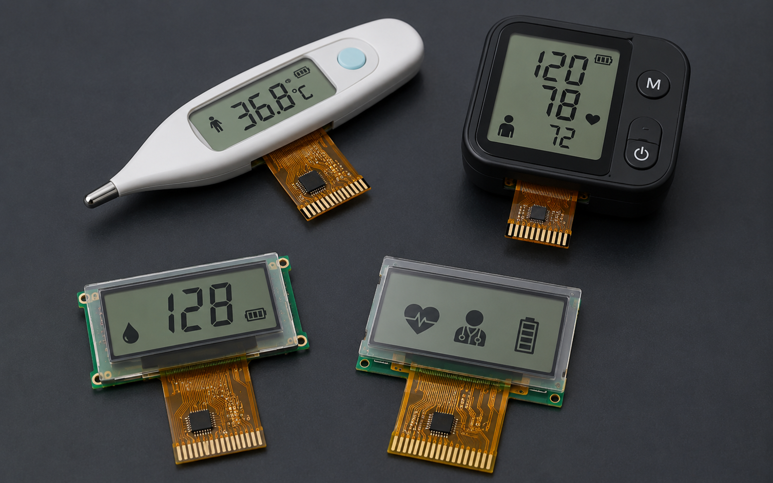
COG LCD display modules are widely used in compact products that need low power consumption, stable readability, simple MCU integration, and a thin.
Leave a comment
This site is protected by hCaptcha and the hCaptcha Privacy Policy and Terms of Service apply.