


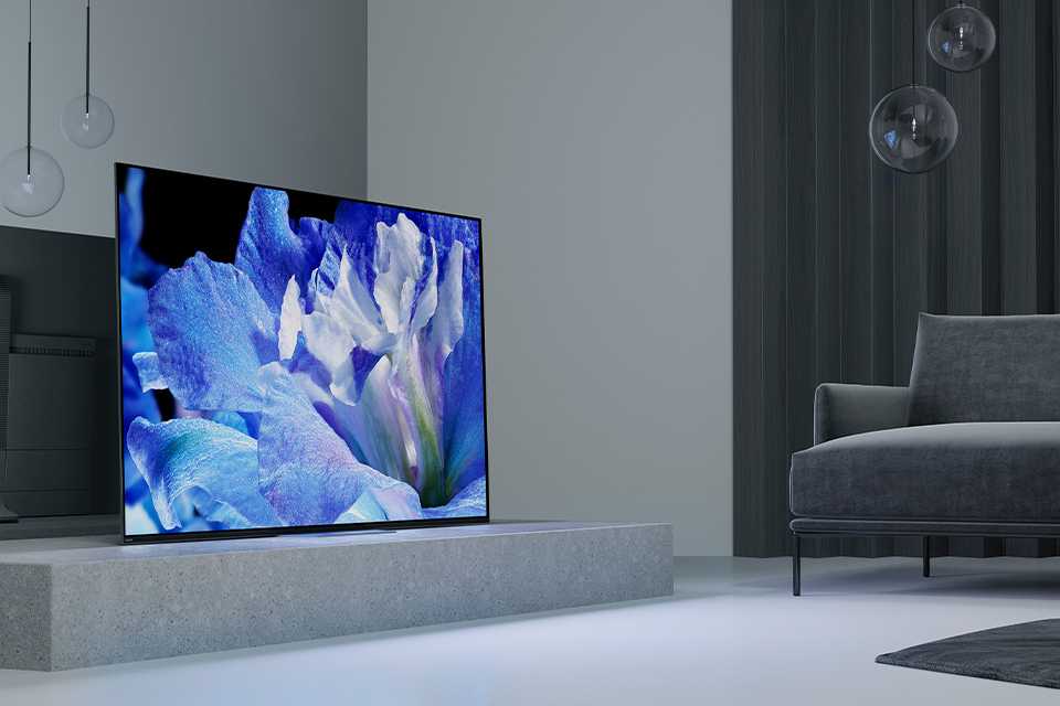
OLED Technology Explained | Structure, Working Principle & Advantages
OLED relies on self-emission from organic layers, with a thickness of approximately 1mm.
It features a 1,000,000:1 contrast ratio, a response time of <0.1ms, and a 178° viewing angle.
The image quality is delicate with pure black levels, and it is thinner, lighter, and more energy-efficient.
Structure
the OLED structure is composed of several layers of organic thin films stacked with a total thickness of only 100 to 500 nanometers.
Its main body includes an ITO transparent anode, organic hole layers (HIL/HTL), a doped emissive layer (EML), organic electron layers (ETL/EIL), and a metal cathode.
These film layers are deposited on a substrate integrated with LTPS or LTPO thin-film transistors (TFTs).
By controlling the current of 8 million independent sub-pixels (using 4K resolution as an example), it achieves pixel-level brightness adjustment and a contrast ratio of over 1,000,000:1.
Bottom Substrate Technology
High-end displays often use aluminosilicate glass with a thickness of 0.5 to 0.7 mm, while mobile devices prefer flexible PI (Polyimide) materials of 10 to 20 micrometers.
The driver circuit layer above it is composed of LTPS or LTPO thin-film transistors, with electron mobility typically between 50 and 100 cm²/Vs, supporting dynamic refresh rates from 1Hz to 120Hz.
Through 7 to 12 photolithography mask processes, the substrate integrates hundreds of millions of transistors, ensuring precise control of pixel current and low-power operation.
In the OLED manufacturing process, the bottom substrate is not just a supporting platform; it carries a complex active-matrix driving circuit.
For rigid screens, choosing a high-performance glass substrate is the industry standard.
This glass usually contains a high proportion of aluminum and silicon to ensure it does not deform during subsequent high-temperature processes exceeding 400 degrees Celsius.
The thickness specifications for the glass are very strict; a common 0.5 mm substrate requires multiple chemical thinning treatments to eventually reduce the weight of the device.
On the surface of the substrate, a buffer layer composed of silicon nitride and silicon oxide is usually deposited first, with a thickness of about 200 to 300 nanometers.
This buffer layer acts as a barrier to impurities, preventing sodium ions inside the glass from diffusing into the semiconductor layer above at high temperatures, thereby ensuring the electrical stability of the transistors.
As industry technical manuals describe: "The quality of the buffer layer directly determines the threshold voltage shift of the thin-film transistors."
Turning to the field of flexible displays, the substrate material changes completely.
Polyimide (PI) has become the mainstream choice due to its extremely high heat resistance and mechanical strength.
On the production line, liquid PI precursor is evenly coated onto a special carrier glass and then cured in a nitrogen environment at 450 degrees Celsius.
The cured PI film layer has a very high glass transition temperature, capable of withstanding subsequent complex thin-film deposition processes.
This material is extremely thin, usually only about 15 micrometers, but its Young's modulus is sufficient to support complex circuit structures.
After all circuit layers are fabricated, the production line uses an excimer laser with a wavelength of 308 nanometers to irradiate the back of the carrier glass.
The laser energy penetrates the glass, breaking the chemical bonds at the interface between the PI film layer and the glass, thus achieving substrate peeling.
This technology, known as Laser Lift-Off (LLO), makes ultra-thin flexible screens with a thickness of less than 0.1 mm possible, with a bending radius that can easily drop below 2 mm.
Currently, Low-Temperature Polycrystalline Silicon (LTPS) technology dominates in small-sized screens.
Its manufacturing process begins with depositing a 50-nanometer-thick amorphous silicon thin film on the substrate, followed by annealing with a high-energy pulsed laser.
Under the instantaneous heating of the laser, amorphous silicon is transformed into polycrystalline silicon, increasing electron mobility from 0.5 to over 80 cm²/Vs.
This high mobility allows transistor sizes to be smaller, thereby freeing up space for high pixel densities (such as above 500 PPI).
However, LTPS transistors have a notable physical flaw: a weak leakage current in the off-state, which generates unnecessary energy loss when displaying static images.
To solve the power consumption issue, LTPO technology emerged and has become popular in flagship smartphones in recent years.
It cleverly integrates two different types of transistors, LTPS and metal oxide (such as IGZO), on the same substrate.
LTPS is responsible for driving the display pixels to respond quickly, while the oxide transistor utilizes its extremely low leakage characteristics for charge retention.
The off-current of the oxide transistor is only at the level of 10 to the power of -14 Amperes, allowing the screen refresh rate to flexibly drop from the traditional 60Hz to 1Hz.
In the ultra-low 1Hz refresh mode, the power consumption of the driver circuit can be reduced by more than 20%.
This hybrid substrate technology requires more than 12 photolithography processes, each involving precise coating, exposure, development, and etching steps, placing extremely high requirements on environmental cleanliness and equipment precision.
To reduce signal delay, wires are usually made of low-resistance materials such as aluminum or copper, and a sandwich structure is used to prevent the diffusion of metal atoms.
On a 4K resolution panel, the total length of the traces on the substrate can reach several kilometers.
These micrometer-scale metal lines are distributed between different insulating layers, achieving inter-layer communication through vertical connection structures called "vias."
Each sub-pixel typically contains 7 transistors and one capacitor; this 7T1C structure is designed to compensate for the non-uniformity generated by LTPS transistors during production, ensuring the overall brightness uniformity deviation of the screen is controlled within 3%.
Electrode Material Construction
Indium Tin Oxide (ITO) has become the mainstream choice due to its excellent electrical conductivity and optical transparency.
This material consists of 90% Indium Oxide and 10% Tin Oxide.
The thin film formed during the vacuum sputtering process has a very low sheet resistance, typically controlled between 10 and 15 ohms per square.
To further optimize the process of holes entering the organic layer from the anode, the manufacturing process subjects the ITO surface to oxygen plasma treatment.
This treatment can increase the surface work function by 0.2 to 0.5 electron volts, thereby narrowing the energy gap between the anode and the hole injection layer.
In terms of structural layout, the flatness of the anode is required to reach the nanometer level.
Any surface protrusion exceeding 10 nanometers may cause local current surges, leading to black spots or short circuits on the screen.
As display physics experimental data shows: "The surface roughness of the anode must be controlled within a root mean square value of 1 nanometer to ensure the continuity of organic thin film growth."
Depending on the optical path design, the structure of the anode changes significantly.
In a bottom-emission structure, light is emitted through the transparent anode and the substrate.
At this time, the thickness of the ITO must be precisely controlled to odd multiples of half the wavelength to enhance light output using thin-film interference effects.
In the top-emission structures used by high-end mobile devices, an additional silver reflection layer about 100 nanometers thick is added below the anode.
This silver metal has a visible light reflectivity of over 95%, redirecting downward-emitted light back to the top.
This three-layer sandwich structure (ITO/Ag/ITO) not only maintains high work function injection characteristics but also significantly reduces voltage drops on large panels, solving the problem of uneven brightness on large-sized screens.
- ITO film thickness: Controlled between 100 nm and 150 nm.
- Visible light transmittance: Must be greater than 85% in the 400 nm to 700 nm band.
- Sheet resistance value: Mass production standards usually require less than 15 ohms per square.
- Surface work function: Must be stabilized above 4.8 eV after treatment.
For the cathode, material selection turns toward low-work-function metals.
To allow electrons to enter the organic electron transport layer smoothly, the work function of the cathode material must be as low as possible.
In early designs, an aluminum layer approximately 100 nanometers thick was the standard configuration, with a work function of about 4.2 eV.
However, the contact between a pure aluminum layer and the organic layer is not ideal, so a very thin layer of Lithium Fluoride (LiF) is deposited between the aluminum and the organic layer, with a thickness of only 0.5 to 1 nanometer.
This Lithium Fluoride layer effectively reduces the injection barrier through a chemical reaction with the aluminum, increasing the electron injection current density several-fold.
In the vacuum thermal evaporation process, this double-layer cathode structure must be completed in an ultra-high vacuum environment of 10 to the power of -7 Torr to prevent reactive metal atoms from being oxidized by residual oxygen.
In today's mainstream top-emission OLED screens, the cathode must balance conductivity and transparency.
To achieve this, engineers developed Magnesium-Silver alloy (Mg:Ag) cathode technology.
By co-evaporating magnesium and silver at a ratio of 10 to 1, an ultra-thin metal film with a thickness of only 10 to 15 nanometers is formed.
Magnesium provides the low work function (about 3.7 eV), while silver is responsible for increasing conductivity and suppressing the aggregation of magnesium atoms, making the film more uniform.
This micrometer-scale semi-transparent cathode produces a physical micro-cavity effect: light reflects back and forth between the bottom reflective anode and the top semi-transparent cathode, and only light of specific wavelengths can exit through constructive interference.
This structure significantly improves the color purity of the display, compressing the spectral full width at half maximum (FWHM) from 60 nanometers to within 30 nanometers, greatly enhancing color performance.
- Mg:Ag alloy ratio: The mixing ratio is typically between 10:1 and 9:1.
- Cathode transparency: At 15 nm thickness, transmittance is maintained at 20% to 30%.
- Electron injection layer thickness: The Lithium Fluoride buffer layer is usually controlled at 0.8 nm.
- Micro-cavity resonance frequency: Matched to Red, Green, and Blue wavelengths by adjusting the total organic layer thickness (approx. 100 to 200 nm).
In addition to the metal electrodes, to further improve light extraction efficiency, a Capping Layer (CPL) made of high-refractive-index organic material is covered above the cathode.
The refractive index of this capping layer is usually between 1.8 and 2.2, with a thickness of about 60 nanometers.
Its presence changes the optical impedance of the cathode surface, reducing plasmonic losses at the metal interface.
By accurately calculating the phase matching between the capping layer and the cathode, the external quantum efficiency of the screen can be increased by more than 20%.
In actual production, this layer usually uses organic small-molecule materials and is continuously grown using vacuum evaporation equipment after the cathode is completed to ensure the interface is not contaminated.
These complex electrode levels together constitute a microscopic charge pump.
The anode continuously pumps in holes, and the cathode continuously injects electrons, with both recombining in the precisely designed organic sandwich.
The thickness deviation of the electrodes must be controlled within plus or minus 3%, because even a 5-nanometer error can cause the micro-cavity resonance frequency to shift, leading to color tint issues on the screen.
Organic Thin Film Interlayers
Holes start from the anode and first pass through a hole injection layer (HIL) with a thickness of about 10 to 60 nanometers.
This layer usually employs materials with strong electron-withdrawing properties, such as hexaazatriphenylene derivatives, to balance the anode work function with the barrier of subsequent organic layers.
Following this is the hole transport layer (HTL) with a thickness between 20 and 100 nanometers, commonly using aromatic amine compounds such as NPB or TPD.
The transport efficiency of holes in this layer directly affects the turn-on voltage of the current.
Experimental physics data shows: "The hole mobility of the HTL layer is usually 1 to 2 orders of magnitude higher than the electron mobility of the ETL layer, an asymmetry that requires precise thickness adjustment to balance."
To prevent electrons from crossing the emissive zone into the anode side, engineers also insert an electron blocking layer (EBL) between the HTL and the emissive layer, which has a higher LUMO level and acts like a wall to intercept electrons within the emissive region.
| Layer Name | Typical Thickness (nm) | Common Material Type | Physical Parameter Goal |
|---|---|---|---|
| Hole Injection Layer (HIL) | 10 - 60 | HAT-CN / PEDOT | Reduce injection barrier to below 0.2 eV |
| Hole Transport Layer (HTL) | 20 - 100 | NPB / TAPC | Mobility reaches 10^-3 cm²/Vs |
| Electron Blocking Layer (EBL) | 5 - 20 | TCTA | T1 level higher than 2.8 eV |
| Emissive Layer (EML) | 15 - 40 | Host-Guest System | Exciton recombination rate near 100% |
The emissive layer (EML) is the part of the organic thin-film interlayer where physical processes are most active, and its construction uses a hybrid system of host materials and guest dopant materials.
The host material is responsible for carrying and transporting electrons and holes into the layer, while the guest dopant material, with a content of only 1% to 10%, is the source of photon emission.
In fluorescent material systems, limited by spin statistics, only 25% of singlet excitons can be converted into light, while 75% of triplet excitons are dissipated as heat.
To break through this physical limit, modern high-end panels extensively use phosphorescent materials or Thermally Activated Delayed Fluorescence (TADF) materials.
Phosphorescent materials, by introducing heavy metal atoms such as iridium or platinum, utilize strong spin-orbit coupling effects to allow triplet excitons to participate in light emission, thereby raising the internal quantum efficiency (IQE) toward the theoretical limit of nearly 100%.
The total thickness of the emissive layer must be fine-tuned according to the wavelength of the required color; for example, the emissive layer of a red pixel is typically thicker than that of a blue pixel to utilize the optical micro-cavity effect to enhance the output intensity of specific wavelengths.
The structure on the electron side is equally precise. Electrons injected from the cathode first pass through an electron injection layer (EIL) with a thickness of less than 1 nanometer.
This layer is usually composed of alkali metal salts such as lithium fluoride or cesium carbonate, which can significantly reduce the effective work function of the cathode metal.
Subsequently, electrons enter the 20 to 50 nanometer thick electron transport layer (ETL), with common materials such as Alq3 or phenanthroline derivatives.
To increase the movement speed of electrons, these materials are often doped with metallic lithium, increasing conductivity several-fold.
Between the electron transport layer and the emissive layer, a hole blocking layer (HBL) plays a crucial constraint role, preventing holes from escaping the emissive layer through an extremely low HOMO level.
This bidirectional blocking structural design ensures that all charges entering the organic layers meet in the narrow nanometer zone of the emissive layer.
As semiconductor physics literature points out: "The spatial confinement of charge carriers is a prerequisite for achieving high brightness output in organic light-emitting diodes."
| Performance Indicator | Fluorescent System | Phosphorescent System | Advanced Standard (TADF) |
|---|---|---|---|
| Internal Quantum Efficiency (IQE) | ~25% | Near 100% | Above 90% |
| Exciton Lifetime (Tau) | Nanosecond (ns) | Microsecond (μs) | Microsecond to Millisecond |
| Color Purity (FWHM) | 50 - 80 nm | 30 - 60 nm | 20 - 40 nm |
| Thermal Stability (Tg) | 80 - 110 °C | 110 - 150 °C | Above 120 °C |
With technological evolution, Tandem structures have begun to be applied in tablets and automotive displays to extend screen life and increase brightness.
This structure vertically stacks two or more organic light-emitting units through a Charge Generation Layer (CGL).
The CGL contains an N-type layer and a P-type layer, which can generate equal amounts of electrons and holes under an electric field, injecting them into the upper and lower light-emitting units respectively.
Under the same current input, two-layer stacked OLEDs can produce double the brightness, or maintain the same brightness while halving the operating current of each layer, thereby reducing the material degradation rate to less than one-fourth of the original.
This multi-layer stacking process requires vacuum evaporation equipment with extremely high control precision, as the total number of layers may exceed 20, and the total thickness tolerance needs to be controlled within 3%.
The purity of organic thin-film materials is required to be above 99.999%. Any metallic impurities or moisture residue at the level of one part per million will lead to non-radiative quenching of excitons, manifesting as a rapid decay in pixel brightness.
During production, these materials are placed in crucibles at 200 to 400 degrees Celsius to sublimate and are deposited onto the substrate in a vacuum environment of 10^-7 Torr.
To prevent cross-contamination between different colored materials, the deposition of the emissive layer usually uses a Fine Metal Mask (FMM) to define pixel locations.
The aperture size on the mask is only tens of micrometers, corresponding precisely to the size of the sub-pixels.
The growth rate of each organic layer is controlled at 0.1 to 0.5 Angstroms per second. This precise molecular-level construction forms the material basis for OLED screens to display brilliant colors.
Working Principle
OLED can operate at low voltages of 2 to 10 Volts, and the total thickness of its internal organic material layers is only 100 to 500 nanometers.
By establishing an electric field between the transparent anode and the metal cathode, electrons and holes meet in the emissive layer (approx. 50 nm thick), where electrical energy is converted directly into visible light.
This mechanism allows pixels to have a response speed of 0.1 milliseconds, zero current consumption when displaying black, and brightness that can expand from 0 to over 3000 nits.
Electrode Charge Injection
The anode typically uses Indium Tin Oxide (ITO), which has high work function characteristics, with initial work function values distributed between 4.5 and 4.7 eV.
To make it easier for holes to enter the Highest Occupied Molecular Orbital (HOMO) of the organic material, ITO surfaces are treated with oxygen plasma or UV-ozone for 5 to 10 minutes in industrial production.
This surface treatment removes surface carbon contaminants and increases oxygen content, thereby raising the work function to over 5.0 eV and reducing the injection energy barrier.
If the injection barrier is maintained below 0.3 eV, charge injection efficiency will grow exponentially.
When the anode voltage reaches the turn-on threshold of 2 to 4 Volts, holes overcome the interface barrier and begin to move toward the hole injection layer at a microscopic drift velocity of several centimeters per second.
The operation logic of the cathode is completely opposite, requiring low-work-function metal materials to ensure smooth electron injection.
Pure Aluminum (Al) has a work function of about 4.3 eV, while the Lowest Unoccupied Molecular Orbital (LUMO) levels of most electron transport layers are around 2.8 to 3.3 eV.
The huge energy difference of over 1.0 eV between the two leads to severe injection obstacles, causing driving voltage to rise and light-emitting efficiency to drop.
To bridge this physical chasm, a thin layer of Lithium Fluoride (LiF) with a thickness of only 0.5 to 1.2 nanometers is usually deposited between the aluminum electrode and the organic layer.
This ultra-thin insulator reacts with aluminum under a strong electric field to form a strong dipole layer at the interface, reducing the effective work function of the cathode to below 3.0 eV.
This interface engineering increases the electron injection current density by 10 to 100 times under the same voltage, ensuring the device can reach a brightness of over 1000 nits under low current drive.
| Electrode/Material Type | Typical Level (eV) | Interface Optimization | Physical Target Value |
|---|---|---|---|
| ITO Anode | 4.5 to 5.2 | Oxygen Plasma Treatment | Work function increase 0.5 eV |
| Aluminum (Al) Cathode | 4.3 | Add 1nm LiF Layer | Effective work function to 3.0 eV |
| Hole Injection (HIL) | 5.2 to 5.5 | Dope with F4-TCNQ | Carrier density 10^18 |
| Electron Injection (EIL) | 2.8 to 3.0 | Alkali Metal Salt Doping | Contact resistance below 1 ohm |
In a room-temperature environment, when the external electric field strength is lower than 10^6 Volts per centimeter, thermionic emission dominates, and electrons rely on thermal energy to cross the interface barrier.
As the voltage increases, the barrier width narrows, and the Fowler-Nordheim tunneling effect, described by quantum mechanics, begins to play a role.
At this stage, electrons no longer need to cross the barrier at a fixed point but instead penetrate the barrier to enter the molecular orbitals of the organic layer.
For a typical device with a thickness of about 100 nanometers, the internal electric field at an operating voltage of 5 Volts is sufficient to support high-density charge flow.
To maintain charge balance, the ratio of injected electrons to holes must be close to 1:1.
If too many carriers of one type are injected, excess charges will pass directly through the emissive layer to the opposite electrode, not only generating ineffective thermal power but also accelerating the chemical degradation of organic molecules, shortening device life from 100,000 hours to less than 10,000 hours.
In actual molecular layer design, the charge injection layer plays the role of an energy ladder.
The hole injection layer often uses HAT-CN, a material with a very deep LUMO level of about 6.0 eV.
This design utilizes the "Fermi level pinning" effect to force a match between the work function of the metal anode and the molecular orbitals of the organic layer.
By generating a charge transfer complex at the interface, the originally huge injection resistance is transformed into a weak ohmic contact.
When measuring J-V characteristic curves, you will find that current density is no longer limited by electrode contact but enters the Space Charge Limited Current (SCLC) mode.
In this mode, charge injection is extremely fast, and the bottleneck of the entire system shifts to the mobility within the organic bulk material.
Interlayer Transport of Substance
Holes first enter the hole transport layer (HTL), whose thickness is precisely controlled between 20 nm and 60 nm, commonly using organic materials such as NPB or TPD.
The HOMO level of NPB molecules is generally around 5.4 eV, while its hole mobility at room temperature is approximately 10^-3 cm²/Vs.
To ensure holes efficiently reach the emissive zone, the thin-film morphology of the HTL must maintain high amorphous stability, with a glass transition temperature (Tg) usually required above 95 degrees Celsius to prevent molecular rearrangement during prolonged power-on heating, which would cause device brightness to decay significantly after 500 hours of operation.
Common ETL materials include Alq3 or TPBi.
The LUMO level of Alq3 is near 3.0 eV, and its electron mobility is significantly lower than that of holes, typically only around 10^-6 cm²/Vs.
This mobility difference of over 1000 times causes the emissive zone to shift.
If the charge flow rate is not manually intervened, a large number of holes will rush through the emissive layer and hit the cathode, causing current loss and generating excess thermal energy.
To balance this physical difference, technicians dope the ETL with a certain proportion of low-work-function alkali metals, such as Cesium Carbonate (Cs2CO3), to compensate for the lack of mobility by increasing free electron concentration.
Experimental data shows that doped ETL can increase current density by 5 to 8 times under a 5 Volt bias, raising the recombination probability of electrons and holes in the emissive layer to over 90%.
| Transport Layer Type | Common Material | Thickness (nm) | Mobility (cm²/Vs) | Energy Level (eV) |
|---|---|---|---|---|
| Hole Transport (HTL) | NPB / TAPC | 30 - 50 | 0.0001 to 0.001 | HOMO: 5.4 - 5.6 |
| Electron Transport (ETL) | Alq3 / TPBi | 20 - 40 | 0.000001 to 0.00001 | LUMO: 2.8 - 3.2 |
| Electron Blocking (EBL) | TAPC / mCP | 5 - 15 | High Hole Cond. | LUMO: 2.0 - 2.4 |
| Hole Blocking (HBL) | BCP / Bphen | 5 - 10 | Wide Bandgap | HOMO: 6.5 - 7.0 |
The distance between organic molecules is about 1 to 2 nanometers, and a charge hopping from one molecule to an adjacent one requires absorbing external thermal energy.
This movement characteristic makes OLED brightness heavily influenced by temperature.
When ambient temperature rises from 25 to 60 degrees Celsius, carrier hopping frequency increases, manifesting as a device total current rise of about 15% at the same voltage.
To maintain display stability, the driver circuit needs real-time current compensation.
At the same time, the transport layer must possess high optical transparency, with refractive indices usually set between 1.7 and 1.9 to reduce total internal reflection losses during light exit.
If the absorption spectrum of the HTL material overlaps with the emission spectrum of the emissive layer, even with high transport efficiency, the final perceived brightness will drop by more than 20% due to internal photon absorption.
The role of the Hole Blocking Layer (HBL) is to build a physical wall using an extremely deep HOMO level.
When holes try to pass through the emissive layer into the ETL, the huge barrier difference forces them to stay at the emissive layer boundary.
Similarly, the Electron Blocking Layer (EBL) uses an extremely high LUMO level to prevent electron leakage.
This "containment" strategy increases carrier concentration within the emissive layer by 3 to 5 times.
According to quantum yield calculations, when the electron-to-hole ratio in the emissive layer reaches a dynamic equilibrium of 1.05:1, the External Quantum Efficiency (EQE) can reach its theoretical maximum.
In mass-produced mobile screens, the positioning accuracy of this multi-layer stack is required to be within 1 nanometer, and any thickness fluctuation exceeding 5% in any layer will cause white balance drift.
- Charge hopping time between molecules is typically measured in picoseconds (10^-12 s).
- Organic thin-film purity must exceed 99.999%. Even 1ppb concentration of metallic impurities will form charge traps, capturing and consuming charges being transported.
- Surface roughness (RMS) of transport layers needs to be controlled below 0.5 nanometers; otherwise, local strong electric fields may cause electrochemical breakdown, forming black spots.
- In high-brightness mode, the current density carried by transport layers can reach 100 mA/cm², placing extreme demands on material bond energy, usually requiring C-N or C-C bonds with binding energies above 3 eV.
Currently, the response time of OLED materials is between 0.01 ms and 0.1 ms, mainly due to the extremely short vertical travel in the transport layers.
Compared to the microsecond-level physical rotation of traditional liquid materials, this electronic cloud overlap conduction of solid-state molecules is thousands of times faster.
Under ultra-high frequency driving (e.g., 240Hz or higher), polarized charge accumulation in transport layer materials has become a new research topic.
If the material cannot quickly return to a neutral state after the voltage is removed, a residual electric field will be generated, manifesting as ghosting on the screen.
To eliminate this effect, new generation transport layers have begun to introduce molecular groups with low polarizability, aiming to compress molecular relaxation time to the nanosecond level.
Photon Generation Mechanism
In the emissive layer (approx. 15 to 30 nm thick), exciton binding energy is typically distributed between 0.1 and 0.5 eV.
According to the spin statistics rule of quantum mechanics, excitons generated by the combination of electrons and holes are divided into two states: 25% are singlets and 75% are triplets.
In early first-generation fluorescent technology, only the 25% of singlets could generate photons through radiative transition, while the remaining 75% of energy dissipated as heat (phonons), locking the IQE of early devices at a 25% theoretical limit.
To break this efficiency bottleneck, second-generation phosphorescent technology introduced heavy metal complexes such as Iridium (Ir) or Platinum (Pt) as dopants.
The strong spin-orbit coupling effect produced by these heavy metal atoms breaks the spin-forbidden rules, allowing triplet excitons to also convert into photons through radiative decay.
Under this mechanism, internal quantum efficiency achieved a leap toward 100%, greatly reducing the heat generated during panel operation.
Taking a green phosphorescent material with a 525 nm wavelength as an example, its luminous efficiency can reach over 80 cd/A, while traditional fluorescent materials are typically only 10 to 15 cd/A.
Inside the emissive layer, energy is primarily transferred through two physical paths.
The first is Förster Resonance Energy Transfer (FRET), a non-contact long-range dipole-dipole interaction with an effective distance usually between 2 and 10 nanometers.
The more the emission spectrum of the host molecule overlaps with the absorption spectrum of the guest molecule, the faster the energy conversion.
The second is Dexter Electron Transfer, which requires physical overlap of molecular electronic clouds and has a very short range, usually less than 2 nanometers.
To prevent excitons from being quenched before emitting light, the triplet energy level (T1) of the host material must be higher than that of the guest material.
For example, in preparing a 460 nm blue-light device, the T1 level of the host material needs to be maintained above 2.8 eV to ensure energy is firmly locked on the emissive molecule without backward flow.
TADF, as a third-generation technology, utilizes an extremely small singlet-triplet energy gap (Delta Est).
When this value is below 0.1 eV, thermal energy in the environment is sufficient to drive triplet excitons back to the singlet state through Reverse Intersystem Crossing (RISC).
Although this process adds tens of microseconds of delay, it also achieves 100% IQE without using expensive rare metals.
Experimental data shows that optimized TADF devices can stabilize at an EQE of over 20% at 1000 nits brightness, comparable to phosphorescent devices.
Despite high internal photon generation efficiency, about 80% of photons are trapped inside the glass substrate or organic layers due to total internal reflection caused by the higher refractive index of organic materials (n=1.7 to 1.9).
To solve this, the production end employs Micro Lens Array (MLA) or internal scattering layer technologies, lifting light extraction efficiency to about 30% to 40%.
In actual display scenarios, significant differences exist in exciton lifetimes among Red, Green, and Blue pixels.
Red exciton radiative decay life is about 1 microsecond, while blue fluorescent exciton life is as fast as 1 to 10 nanoseconds.
This speed difference is why blue pixels are more prone to chemical bond breakage under long-term high-current operation, leading to screen burn-in or color shift.
- Singlet exciton de-excitation speed is typically 3 orders of magnitude faster than triplets.
- Doping ratios in the emissive layer are generally controlled between 1% and 10% by weight.
- At 5 Volts, the exciton generation rate per unit area can reach 10^16 per second per square centimeter.
- The wavelength of a photon is determined by the energy difference when an exciton falls back from the excited state to the ground state (S0).
In high-current-density environments, quenching reactions occur between excitons, where two excitons collide leading to non-radiative annihilation of one.
This is especially evident when brightness exceeds 5000 nits, manifesting as efficiency roll-off.
To alleviate this, engineers design complex gradient doping structures to expand the exciton generation zone from a narrow interface to the entire 20 nm thick emissive layer, reducing local exciton density.
Additionally, the interaction between Polarons and excitons is another energy loss path, where charged particles capture exciton energy and convert it into kinetic energy, a process particularly intense in blue materials.
"By adjusting the dipole moment direction of organic molecules, emitted photons can be directed more vertically toward the screen surface."
To further improve color purity, modern OLED panels use micro-cavity effect structures.
By precisely adjusting the total optical thickness between the anode and cathode, light of specific wavelengths forms constructive interference between the two reflective electrodes.
This optical design can compress the FWHM from 60 nm to within 30 nm, thereby achieving higher color gamut coverage.
Under the DCI-P3 standard, this physical interference mechanism ensures red pixels emit pure 630 nm light without orange spectral components.
Advantages
OLED screens have a measured black level brightness of 0 nits, with contrast data trending toward infinity.
Their grayscale response speed is typically faster than 0.1ms, supporting 100% DCI-P3 color gamut coverage.
On a physical level, by eliminating the backlight layer, the total panel thickness can be controlled below 1mm.
In dark mode, screen power consumption is reduced by about 40% to 60% compared to LCD, and it supports flexible physical forms with a bending radius of less than 3mm.
Pixel-Level Complete Shut-off
Each sub-pixel is an independently controlled light emitter. When the display control circuit sends a zero-brightness signal to a specific pixel, the current flowing through that pixel's TFT is completely cut off.
At this point, the recombination of holes and electrons in the organic emissive layer stops, and the pixel no longer generates any photons.
This physical-level shut-off allows the screen to maintain a measured brightness of 0.0000 nits when displaying black images.
In contrast, traditional LCD panels have backlight modules that are always on; even with local dimming, light still scatters through liquid crystal layers, resulting in a residual brightness of 0.1 to 0.5 nits in black areas.
On a 4K resolution panel, there are over 8.29 million independent light-emitting pixels.
In an RGB sub-pixel arrangement, this includes over 24.8 million physical units that can be switched independently.
This extremely high density of light control units gives OLED natural precision when handling high-contrast images.
In scenes like a starry sky, there is no mutual interference between bright star pixels and adjacent deep-space black pixels.
Conversely, mainstream high-end Mini-LED TVs, even with 2000 dimming zones, must control about 4000 pixels per zone.
When a small bright spot appears, the Mini-LED must turn on the entire zone, causing a gray-white "halo" around the spot, whereas OLED eliminates this optical flaw through independent pixel shut-off.
Since contrast ratio is calculated as peak brightness divided by minimum brightness, when the denominator is 0, the value physically tends toward infinity.
This characteristic greatly enhances the transparency of the image.
When viewed in low ambient light, the black displayed on the screen blends perfectly with the physical environment, making it impossible for users to perceive the screen edges.
This deep black performance is the foundation for HDR 10+ or Dolby Vision standards.
Only when baseline brightness is low enough can grayscale changes in dark areas be accurately restored, revealing texture details otherwise hidden by backlight scattering.
The total power consumption of the screen is the accumulation of each working pixel, and the power consumption for black pixels is 0 Watts.
Technical data shows that when users enable Dark Mode and the Average Picture Level (APL) stays around 10%, display power consumption can drop by more than 65% compared to a full white background.
This emission-on-demand logic avoids thermal loss in areas that don't need to be displayed.
In Always-on Display (AOD) functions, only less than 1% of pixels are driven at very low frequencies, with icons or time info floating over a pure black background, usually consuming less than 1% of total battery per hour.
Regarding control precision at extremely low grayscales, driver ICs manage the switch from full black to dim light through precise V-offset compensation.
While pixels can be completely closed, they must quickly move from ground state to excited state upon receiving weak signals.
High-quality OLED panels can achieve 0.1% brightness adjustment increments, ensuring no banding occurs in near-black areas.
This micro-operation capability for low-brightness pixels gives shadows in movies a strong sense of depth, allowing different shades of black to be clearly distinguished.
OLED panels do not require liquid crystal layers or polarizer stacks, making the light exit path extremely short.
This structure reduces internal total reflection and diagonal light leakage, ensuring photons spill out vertically only above excited pixels.
Even at a 175-degree side angle, shut-off black areas remain absolutely black, without the whitening or blue-tint color shift common in traditional screens.
This optical stability is vital for scenarios like automotive displays with high viewing angle requirements, ensuring pure backgrounds for instrument readings under various lighting changes.
Millisecond-Level Image Response
Traditional LCDs rely on voltage to change the arrangement angle of liquid molecules to control light, a physical rotation limited by viscosity; even on high-end gaming monitors, this takes 1ms to 5ms.
In contrast, OLEDs are electroluminescent devices where image switching only involves the migration and recombination of carriers (electrons and holes) within organic layers.
This sub-microsecond microscopic process keeps GtG response times typically between 0.01ms and 0.1ms.
As refresh rates rise to 240Hz or 360Hz, frame dwell times shorten to 4.16ms or 2.77ms.
Within such short windows, display elements must complete a total conversion from one color state to another.
If response speed is slower than the frame interval, residual images from the previous frame overlap with the current one, producing ghosting.
OLED's nearly instantaneous level-switching ensures each pixel completes accurate coloring before the next frame arrives at very high refresh rates.
- GtG Performance: Laboratory data shows OLED switching times are extremely balanced across grayscales, without the significant delays seen in LCD during deep gray transitions.
- Motion Blur Suppression (MPRT): Although OLED still uses sample-and-hold driving, the extremely short pixel conversion time reduces blur width on moving edges, making dynamic images sharper.
- Input Lag: Combined with high-speed driver circuits, the time difference from display interface signal to pixel emission is compressed, providing low latency for competitive software.
Since no physical molecular movement is involved, charge migration remains ultra-fast even in extreme cold at -20 degrees Celsius.
LCD response degrades to over 50ms in the cold due to increased viscosity, leading to severe ghosting.
This stability makes OLED consistent in automotive HUDs or outdoor professional monitors, ensuring clear readings in any climate.
"The speed of pixel state switching determines the restoration accuracy of dynamic content, and OLED pushes this limit to the scale of electronic migration."
This speed advantage is not only perceptible to the eye but also shows high refresh purity under high-speed cameras.
When displaying 1000fps video, every OLED transition is crisp, without diffuse interference from filters or backlights.
For VR devices, sub-0.1ms response helps alleviate motion sickness caused by desync between head movement and screen updates.
From a circuit driving perspective, TFT current output efficiency affects the response waveform.
Modern OLED driver ICs use Overdrive technology and precise current management to realize fine suppression of pixel brightness.
Even with extreme loads jumping from 0% to 100% brightness, organic layers respond and release photons in nanoseconds.
- Visual Smoothness: Scrolling text or pages does not show colored dispersion or shadows, providing a reading experience closer to paper.
- Sampling Rate Adaptation: Supports extremely high touch sampling rates; visual feedback is almost simultaneous with physical touch, reducing lag.
- Color Synchronization: Red, Green, and Blue sub-pixels show highly synchronized turn-on speeds under current, avoiding color banding on fast-moving edges.
The combination of high refresh rates and millisecond response gives OLED irreplaceable advantages in professional broadcasting.
Monitors can faithfully restore every detail of sports footage at 60fps or 120fps.
Without the need for complex zone-dimming calculations, each pixel response is local and independent of its neighbors, ensuring highlights and shadows are presented accurately and independently without overlap.
Extreme Panel Thinness and Lightness
LCD thickness is primarily limited by its complex stack, requiring backlights, light guides, reflectors, and diffusers, with the module typically between 3mm and 5mm.
Self-emissive panels remove all these components, compressing the total thickness to 0.6mm to 1.0mm.
Without the backlight, the overall weight also drops. At the same area, a self-emissive panel is typically only about 30% the weight of an LCD, providing high weight-reduction margins for mobile devices, wearables, and wall-mounted displays.
| Component | LCD Specification | OLED Specification | Trend |
|---|---|---|---|
| Backlight Unit (BLU) | 2.5mm - 4.5mm | 0mm (None) | Total elimination |
| LC & Filter Layer | 0.5mm glass + LC | Nano-scale Organic Layers | 90%+ reduction |
| Substrate | 0.5mm - 0.7mm Glass | 0.1mm PI Film | Flexible & Ultra-thin |
| Encapsulation | Glass bonding | Thin Film Encapsulation (TFE) | -0.4mm space |
| Total Weight (6") | ~50g - 70g | ~15g - 25g | ~60% lighter |
In self-emissive technology, organic functional layers are located between the anode and cathode, with a total thickness usually not exceeding 500 nanometers.
During production, HIL, HTL, EML, and ETL are evaporated onto the substrate in layers only tens of nanometers thick.
This ultra-thin stack doesn't need micrometer gaps for fluid like LCD does, eliminating gravity-induced deformation and ensuring stable display under pressure or bending.
In high-end mobile devices, traditional rigid glass substrates are replaced by Polyimide (PI) materials only 10 to 50 micrometers thick.
PI has high heat resistance and mechanical strength, maintaining flexibility at processes over 400 degrees Celsius. Display modules using such substrates can reach a bending radius below 3mm.
In structural design, manufacturers use COP (Chip on Plastic) packaging to fold the driver circuit at the bottom directly to the back of the panel.
This process compresses the bottom bezel (chin) from 5mm to less than 2mm, achieving high screen-to-body ratios.
"Every 1mm reduced in display thickness can free up space for about 100mAh of battery capacity."
This space conversion ratio makes thinness more than just an aesthetic pursuit.
In precision devices like smartwatches, every micrometer saved is vital.
Top encapsulation currently uses TFE technology, stacking inorganic and organic layers for a barrier less than 10 micrometers thick to replace rigid cover glass.
- Touch Integration: Traditional devices need an extra 0.5mm touch glass. Modern self-emission technologies lithograph touch sensors directly onto the TFE (e.g., Y-OCTA), reducing sensor thickness to the 0.001mm level and lowering reflection.
- Thin Polarizers: To eliminate reflections, panels use polarizers. New tech uses Color Filters on Encap (COE) to replace the polarizer, reducing thickness from 150 to under 50 micrometers while improving light efficiency.
- Circuit Simplification: Combined with LTPO backplanes, driver transistor layouts are more compact. Even at 500+ PPI, circuit layer wiring widths enter the nanometer range.
In traditional displays, light must pass through polarizers, LC layers, and color filters, losing over 90% of energy.
In self-emissive structures, light exits through the ultra-thin encapsulation almost instantly.
Data shows that at a 60-degree viewing angle, brightness decay is much lower than LCD, and the color shift (Delta E) remains stable within 1.5.
Read more

Selection requires matching I2C/SPI interfaces; OLED features a 100,000:1 contrast ratio, LCD targets 500 nits brightness; Confirm 3.3V/5V voltage compatibility; Select ISO-certified suppliers that...
AMOLED is a pixel self-emissive technology featuring an ultra-high contrast ratio of 1,000,000:1. Black pixels do not emit light, making it more energy-efficient with more vibrant colors. It respon...
Leave a comment
This site is protected by hCaptcha and the hCaptcha Privacy Policy and Terms of Service apply.