


TFT LCD vs IPS LCD | Key Differences, Response Time & Color Accuracy
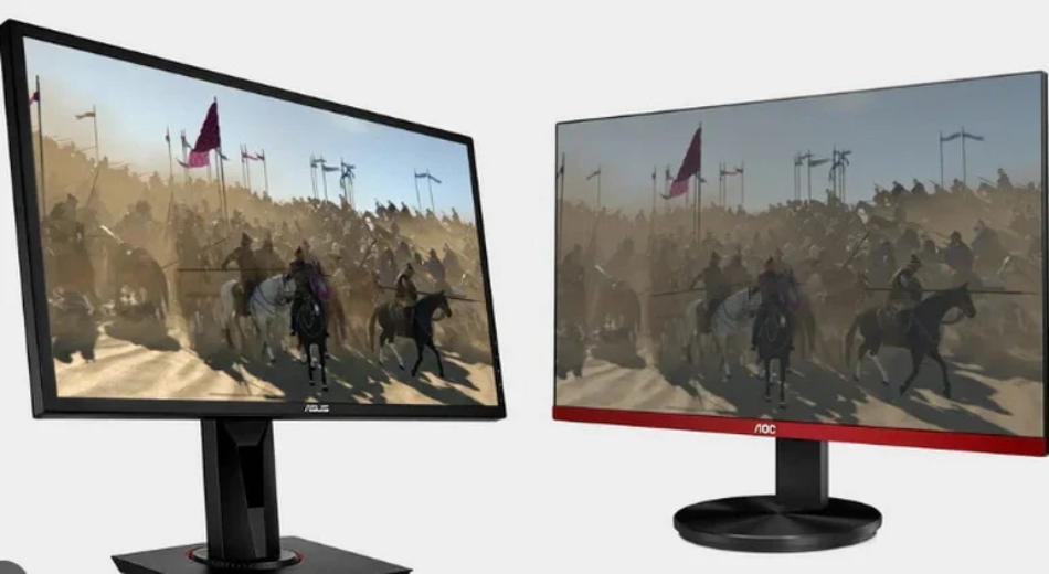
IPS panels, with their 178° wide viewing angle and 99% sRGB color gamut, far surpass ordinary TFT (TN) panels in color accuracy, making them suitable for image processing;
Although their response time of around 4ms is slower than the 1ms of TFT panels, it is recommended to prioritize IPS panels except for professional e-sports, and to use a colorimeter to keep the color accuracy Delta E below 2 for the best visual experience.
Key Differences
TN adopts a vertical arrangement and natively supports 0.5ms to 1ms GtG response times, but the color depth is mostly 6-bit dithered to 8-bit, and color inversion occurs when the viewing angle exceeds 160 degrees.
IPS adopts horizontal switching technology, achieving 178-degree omnidirectional viewing without color shifting, natively supports 8-bit or 10-bit color depth, and covers 100% sRGB.
Due to the lower aperture ratio of IPS, maintaining equivalent brightness requires increasing backlight power consumption by approximately 15%, and the static contrast ratio usually stabilizes at 1000:1.
Physical Structure Differences
How exactly do the molecules move?
In the TN-TFT structure, liquid crystal molecules are located between the upper and lower alignment layers, presenting a 90-degree twisted spiral arrangement.
When no voltage is applied, light follows the direction of the molecular rotation and passes through the polarizer.
After voltage is applied, the molecules quickly "stand up" from the horizontal state to a state vertical to the glass substrate.
This displacement journey from lying flat to standing upright is extremely short, and the mechanical inertia at the physical level is small.
In contrast, IPS technology spreads the liquid crystal molecules flat on the substrate.
Whether in the on or off state, the molecules always maintain an orientation parallel to the glass substrate.
When voltage is applied, the molecules perform a "circular motion" rotation within the horizontal plane.
Although this rotating action is spatially neater than the flipping action of TN screens, due to the characteristics of intermolecular forces, its rotation cycle is usually longer than the flipping cycle of TN.
| Dimension of Motion | TN-TFT Structure | IPS Structure |
|---|---|---|
| Motion Trajectory | Vertical flip (like turning a page) | Horizontal rotation (like turning a dial) |
| Molecular Arrangement | Spiral twist (90 degrees) | Parallel arrangement |
| Spatial Displacement | Three-dimensional space flip | Two-dimensional plane rotation |
Where are the electrodes placed?
TN screens use an opposing electrode distribution, with one layer of electrodes attached to the top color filter glass and the other layer on the bottom TFT glass.
The IPS structure eliminates the transparent electrodes on the top glass and places both the positive and negative electrodes on the bottom TFT glass substrate.
This layout is called "In-Plane Switching," and the generated electric field lines no longer penetrate vertically but are distributed in a comb shape in the horizontal direction.
Because the electric field is generated only at the bottom, when driving the liquid crystal molecules to rotate, only the molecules near the electrode side receive the most direct force.
Molecules further away are dragged by intermolecular traction, which results in the driving voltage usually needing to be 20% to 30% higher than that of TN screens.
The path of light penetration
In the TN structure, when light passes through the liquid crystal layer, because the molecules are standing vertically or twisted, the light encounters different refractive indices when passing through molecular gaps at different angles.
When the observer deviates from the direct front position, the observed phase difference increases rapidly, causing light that should have been blocked to leak out, or light that should have penetrated to be blocked.
Since the molecules always rotate in the horizontal plane, no matter which angle the molecules turn to, the effective optical path length of light passing through the liquid crystal layer is almost equal.
The physical characteristics of light remain consistent under different viewing angles.
Even at a large angle of 178 degrees, the change in polarization state generated after light passes through the liquid crystal layer is very weak, thereby achieving extremely low color deviation.
Reasons for high or low aperture ratio
In terms of physical structure, IPS is at a disadvantage.
- Electrode Occlusion: Both electrodes of IPS are on the same side, and to generate a uniform horizontal electric field, the electrodes are usually made into comb-shaped thin strips.
- Light Transmission Area: The electrodes of TN screens are distributed on two layers of glass, and the top electrode is a fully covered transparent conductive layer, which does not block light.
- Data Quantification: Under the same process, the aperture ratio of TN screens can reach over 80%, while IPS is often only 60% to 70%. This means that to achieve a screen brightness of 300 nits, IPS must be equipped with a higher-power backlight module, leading to an increase in overall power consumption.
Reaction after pressing the screen
When the screen surface is pressed by a finger, the vertically arranged molecules are easily displaced by mechanical pressure, causing the electric field control to fail.
Light instantly leaks out in large quantities, forming obvious "water ripples."
The liquid crystal molecules of the IPS structure have higher structural strength because they are arranged horizontally and have a stronger anchoring force between them.
When squeezed by external force, the horizontal posture of the molecules is less disturbed, and the molecular position can be quickly restored.
This physical characteristic makes IPS the standard configuration for touch devices because it does not produce image flickering or ghosting during finger sliding.
The shape of pixel arrangement
If you observe the two types of panels with a macro lens, you will find that the shapes of the pixel grains are completely different.
- TN Pixels: Usually present a rectangle or square, and the light-transmitting area inside the pixel is very regular.
- IPS Pixels: To optimize color shift, the sub-pixels of IPS are usually designed as "fishbone" or "V-shaped." This chevron-shaped electrode design can divide a pixel into two different orientation domains.
- Compensation Effect: When the molecules rotate, the optical deviations generated by the two sides of the V-shape can cancel each other out. Although this complex physical shape increases manufacturing difficulty, it further strengthens the isotropy of the image, making the color temperature of the picture more stable when viewed from the side.
Wiring of the transistor backplane
In IPS panels, since each sub-pixel needs to control complex comb-shaped electrodes and often requires higher driving voltage, the circuit wiring density of its backplane is higher than that of TN screens.
- Capacitance Effect: The storage capacitor inside the IPS pixel needs to be made larger to maintain the stability of the molecule's position after horizontal rotation.
- Process Precision Level: IPS has extremely high requirements for controlling the gap (Cell Gap) between glass substrates, and the error must be controlled within 0.1 microns. If the gap is uneven, the horizontal electric field will be distorted, causing color blocks or uneven brightness on the screen.
Color Reproduction Ability
How many colors can be displayed exactly
TN panels are limited by physical arrangement, and most native bit depths are only 6-bit.
The Red, Green, and Blue (RGB) color channels can only display 64 grayscale levels each.
Through simple multiplication, 64 times 64 times 64 results in 262,144 colors.
To bridge this gap, TN screens usually use a pixel dithering technology called FRC (Frame Rate Control).
By making pixels flicker quickly between two colors to simulate an intermediate color, they barely achieve an effect similar to 16.7 million colors.
In contrast, the native bit depth of IPS panels usually starts from 8-bit, and high-end models even reach 10-bit.
| Bit Depth Type | Grayscale Levels Per Channel | Total Displayable Colors | Technical Method |
|---|---|---|---|
| Native 6-bit (TN) | 64 | 262,144 | Hardware physical limitation |
| 6-bit + FRC (TN) | 256 (Simulated) | Approx. 16.7 Million | Pixel rapid flickering simulation |
| Native 8-bit (IPS) | 256 | 16,777,216 | Hardware native support |
| 10-bit (High-end IPS) | 1024 | Approx. 1.07 Billion | Hardware native support |
The advantage of native 8-bit or 10-bit is that it does not need to deceive the human eye through flickering, and the color display is more stable.
When processing delicate skin tones or dark shadow transitions, the image texture exhibited by IPS far exceeds that of TN screens relying on dithering algorithms.
How much color range is covered
Common standards include sRGB, Adobe RGB, and DCI-P3.
- sRGB Standard: This is the universal standard for the internet and daily office work. The color gamut coverage of ordinary TN screens can usually only reach about 90% to 95% of sRGB. Reflected in numerical values, it is approximately equivalent to 72% of NTSC color gamut.
- DCI-P3 Standard: This is the wide color gamut standard used by the film industry. Modern IPS panels can easily cover 95% to 98% of DCI-P3 color gamut.
-
Color Saturation Data:
- TN Panels: Due to lower backlight filtering efficiency, colors often look relatively flat, or even have a washed-out, faded visual feel.
- IPS Panels: Through efficient filters and high-purity backlight beads, colors are extremely saturated. In High Dynamic Range (HDR) content, IPS can accurately present bright and vivid primary colors.
Is the color accurate?
Color accuracy is usually quantified by Delta E (abbreviated as dE), which represents the distance between the color displayed on the screen and the true standard color.
- dE > 5: The human eye can obviously see color deviation; this is the common state of low-end TN screens.
- 3 < dE < 5: The level of a screen after preliminary calibration.
- dE < 2: This is the factory standard for professional-grade IPS monitors.
Under different brightness levels, the color coordinate offset of IPS is very small.
If we increase the brightness from 50 nits to 300 nits, the white point color temperature fluctuation of IPS is usually controlled within 200K.
However, when the brightness of a TN screen changes, because the deflection angle of liquid crystal molecules is non-linear, obvious cooling or yellowing phenomena often occur.
Smoothness of light and dark transitions
When you watch a gradient video from pure black to pure white on the screen, the difference in physical structure will be directly exposed. This phenomenon is called color banding.
- Performance of TN Screens: Since there are only 64 real grayscale levels, obvious visible stepped color blocks will appear on the gradient bar.
- Performance of IPS Screens: 256 or 1024 native grayscale levels make color transitions as smooth as silk. In professional post-production video editing, this smoothness ensures that the material quality is not misjudged due to insufficient screen bit depth during color grading.
Will the color change if I change the angle?
When the viewing angle deviates from the direct front by 30 degrees, the data performance difference between the two panels is huge.
| Viewing Angle | TN Color Coordinate Shift (Δu'v') | IPS Color Coordinate Shift (Δu'v') | Visual Feedback |
|---|---|---|---|
| 0 Degrees (Front) | 0.00 | 0.00 | Normal picture |
| 30 Degrees (Side) | Approx. 0.04 | Approx. 0.008 | TN discolors significantly, IPS basically unnoticeable |
| 60 Degrees (Large Angle) | Exceeds 0.10 | Approx. 0.015 | TN color inversion, IPS remains accurate |
If you observe a TN screen from below, areas that should be bright will become dark, and areas that should be dark will become bright.
IPS has extremely small color coordinate displacement within the wide angle of 178 degrees, ensuring that the image content seen during multi-person collaborative work is consistent.
Stability of the Gamma curve
The Gamma value determines the neutral gray and contrast of the image. The international general standard is usually set at 2.2.
- Stability of IPS: The Gamma curve of IPS is usually very close to the standard straight line of 2.2. The brightness distribution of the image fits the physiological perception of the human eye very well; bright areas are bright, and dark details are preserved.
- Fluctuation of TN: The Gamma curve of TN panels fluctuates violently with changes in viewing angle and brightness. At the edge of the screen, due to the slight deviation in viewing angle, the Gamma value may slide to 1.8 or soar to 2.6.
Response Time
Response time represents the speed at which a pixel switches from one grayscale to another (G2G).
The limit for TN panels is 0.5ms to 1ms, standard IPS sits at 3ms to 5ms, while Fast-IPS has shortened this to 1ms.
At a 144Hz refresh rate, the single frame duration is 6.94ms. If the response speed is slower than this value, the image state conversion cannot be completed before the next frame loads, resulting in visual ghosting.
Physical Flipping Differences
Queuing Posture of Liquid Crystal Molecules
Molecules undergo a 90-degree twist from the bottom substrate to the top substrate, forming a path similar to a spiral staircase.
Light rotates along this spiral structure and passes through the polarizer, making the screen appear bright.
The characteristic of this structure is that the molecules have natural tension in three-dimensional space and are in a quasi-excited state ready to "stand up" at any time.
In contrast, the liquid crystal molecules of IPS (In-Plane Switching) panels are completely parallel to the glass substrate in their initial state.
All molecules lie flat in the plane like neatly arranged pencils. This arrangement does not require the molecules to undergo vertical displacement but rather horizontal rotation within the same plane.
Action After Applying Electricity
Driven by a vertical electric field, the molecules of the TN panel quickly erect from a horizontal twisted state to a vertical direction.
Because the molecules only need to tilt upwards, the physical span of the movement path is small, usually completed within a thickness space of 2 microns to 2.5 microns.
This vertical deflection moment reacts sensitively, allowing pixels to block light in an extremely short time, achieving switching within 1 millisecond.
IPS panels rely on a horizontal electric field. After power is applied, the molecules rotate in place like a compass within a parallel plane.
Since the long axis of the molecule is always parallel to the substrate, it encounters significant friction from surrounding liquid crystal molecules during rotation.
The physical mechanical resistance of this planar rotation is higher than the vertical flipping of TN, so the molecular reset speed of standard IPS is usually slower than TN.
Even in high-performance IPS, this rotating action requires a higher driving voltage to counteract the viscous resistance of the liquid molecules.
Where the Electrodes Grow
TN panels use a sandwich design, with electrodes located on the upper and lower glass substrates respectively.
After electrification, a very uniform vertical electric field is formed between the two layers of glass, and the pulling force felt by the liquid crystal molecules is omnidirectional.
This structure is similar to two magnets attracting up and down; the molecules are stressed uniformly, and the starting speed is extremely fast.
IPS technology places all electrodes on the bottom substrate.
This single-sided wiring method generates a Fringe Field.
The electric field lines start from the bottom pixel electrode, bypass the liquid crystal molecules, and return to the common electrode.
Only the bottom end of the liquid crystal molecule receives a strong force, while the end far from the electrode receives a weak force.
To make the entire segment of liquid crystal molecules rotate synchronously, a more complex comb-toothed electrode design must be used.
This physical characteristic of uneven force caused the response time of IPS in early technologies to be as high as 25 milliseconds to 50 milliseconds, which was not improved until the appearance of modern high-transmittance FFS technology.
How Wide is the Glass Gap
Cell Gap is a physical constant that affects speed.
According to fluid dynamics formulas, response time is proportional to the square of the cell thickness.
In pursuit of extreme speed, TN panels usually compress the glass gap to about 2.0 microns.
A narrower gap means fewer liquid crystal molecules, less movement obstruction, and stronger explosive power of electric field intensity over a short distance.
To guarantee color uniformity and light transmittance, IPS panels usually maintain their cell thickness between 2.8 microns and 3.5 microns.
As the cell thickness increases, the fluid viscosity that molecules need to overcome during rotation rises accordingly.
If the cell thickness increases from 2 microns to 3 microns, the theoretical response time will increase to 2.25 times the original.
This requires IPS to use lower viscosity liquid crystal materials to compensate for the delay caused by physical spacing, which is also one of the reasons for the higher cost of high-end Fast-IPS screens.
Refresh Rate Synchronization
How long is each frame exactly
Electronic signals send image commands to the panel a fixed number of times per second.
The higher the refresh rate, the shorter the time each frame stays.
This segmentation in time forms the sense of continuity in dynamic images.
If the response time is slower than this cycle, the monitor cannot fully display the content of every frame.
| Refresh Rate Frequency (Hz) | Single Frame Duration (ms) | Response Time Upper Limit Requirement (ms) |
|---|---|---|
| 60Hz | 16.67 ms | Must be lower than 16.67 ms |
| 120Hz | 8.33 ms | Must be lower than 8.33 ms |
| 144Hz | 6.94 ms | Must be lower than 6.94 ms |
| 240Hz | 4.17 ms | Must be lower than 4.17 ms |
| 360Hz | 2.78 ms | Must be lower than 2.78 ms |
| 540Hz | 1.85 ms | Must be lower than 1.85 ms |
Pixel color change can't keep up with refresh
When the new frame command from the graphics card arrives, the liquid crystal molecules begin to rotate. If the refresh rate is set at 165Hz, there will be a new image signal every 6.06 milliseconds.
Suppose the average grayscale response time of a certain IPS panel is 8 milliseconds; then at the end of the first frame signal, the liquid crystal molecules have only completed about seventy percent of the rotation action.
At this point, the second frame signal has already arrived. The liquid crystal molecules have to abandon the current rotation target and turn to move towards the angle required by the second frame.
This overlapping state where the previous frame is unfinished and the next frame has begun manifests visually as diffusion and blurring of image edges.
For high-speed moving objects, this delay causes a trail (ghosting) several pixels long to appear behind the object.
Only when the response time is far lower than the single frame duration can the pixel enter a stable state before the next frame loads.
Running logic of variable frequency synchronization
In actual use, the frame rate (FPS) output by the graphics card is often unstable.
To solve the screen tearing problem, the VESA standard established Adaptive-Sync, while NVIDIA and AMD launched G-Sync and FreeSync hardware solutions respectively.
These technologies allow the monitor's refresh rate to dynamically match the output rate of the graphics card.
| Sync Technology Type | Signal Processing Method | Response Performance |
|---|---|---|
| Fixed Refresh Rate | Forced update every 6.94 ms | Prone to screen tearing or stuttering |
| G-Sync (Hardware) | Built-in chip adjusts pixel driving voltage in real-time | Response time changes dynamically with frame rate |
| FreeSync (Standard) | Adjusts gap via DisplayPort protocol | Response might slow down at low frame rates |
When variable frequency synchronization is enabled, if the game frame rate drops from 144 frames to 60 frames, the monitor's refresh interval will automatically lengthen from 6.94 milliseconds to 16.67 milliseconds.
At this time, since pixels are allowed a longer conversion time, the slight ghosting that originally appeared at 144Hz will disappear at 60Hz.
Motion Blur Quantification Indicators
When the industry evaluates synchronization performance, besides looking at G2G (Gray to Gray), it also refers to MPRT (Motion Picture Response Time).
MPRT measures the degree of blurring perceived by the human eye, which is highly correlated with the refresh rate.
On a 60Hz screen, even if the G2G of liquid crystal molecules reaches 0 milliseconds, MPRT will still remain around 16.67 milliseconds, which is determined by the "sample-and-hold" display characteristic.
To lower MPRT, one must increase the refresh rate or use Black Frame Insertion technology.
| Technical Means | Physical Principle | Visual Benefit |
|---|---|---|
| Increasing Hz Value | Reducing the display duration of each frame image | Reduces blur caused by persistence of vision |
| Black Frame Insertion (BFI) | Inserting a pure black background between two frame images | Forcibly clears the afterimage on the retina |
| Backlight Strobing | Turning on the backlight only after pixels complete conversion | Obtains clear dynamic effects similar to CRT |
Sync Range and Response Overshoot
The monitor's synchronization function usually has a working frequency range, such as 48Hz to 144Hz.
If the frame rate exceeds this range, the synchronization mechanism will fail.
To ensure good response performance throughout the interval, the monitor uses Variable Overdrive.
When the refresh rate is higher, the drive circuit applies a higher voltage to force the liquid crystal molecules to turn quickly.
When the refresh rate decreases, the voltage decreases accordingly to prevent overshoot.
So-called overshoot is when the pixel changes color past the mark, causing white bright edges or color anomalies to appear at the edge of the object.
Perfect synchronization requires the driving voltage to be adjusted precisely within microseconds according to the fluctuation of the refresh rate, ensuring that every color change action can be accurately completed within the current frame cycle.
Performance at Different Rates
In a 360Hz environment, the total time left for the system for signal transmission, command decoding, and pixel flipping is only 2.78 milliseconds.
Even a 1-millisecond signal delay will crowd out the rotation time of the liquid crystal molecules.
| Application Scenario | Frame Rate Fluctuation Range | Requirements for Sync |
|---|---|---|
| Competitive Games | 240 - 500 FPS | Extremely high, requires ultra-fast conversion within 1 ms |
| AAA Single Player | 60 - 120 FPS | Medium, requires stable variable overdrive drive |
| Video Editing | Fixed 24/60 FPS | Lower, as long as it aligns with raw footage |
Currently, top-tier TN panels and Fast-IPS panels, in order to maintain image clarity at 360Hz or even 540Hz, usually sacrifice some color bit depth and ensure the synchronization frequency of electrical signals by reducing data bandwidth usage.
Dynamic Clarity Performance
Residue of Pixel Color Change
G2G (Gray to Gray) response time measures the time required for a pixel to change from 10% target brightness to 90% target brightness.
Even if a Fast-IPS panel claims to reach 1 millisecond, the remaining 10% brightness residue will still stay on the screen.
| Residual Brightness Ratio | Visual Description | Cause |
|---|---|---|
| 5% Brightness Residue | Extremely slight shadow | Reset speed of liquid crystal molecules slows down in the final stage. |
| 15% Brightness Residue | Obvious trailing (Ghosting) | Liquid crystal molecules fail to reach the target angle before the current frame ends. |
| Over 30% Residue | Severe image overlap | Response speed is far lower than refresh rate; multi-frame images overlap on the retina. |
For TN panels, because the molecule flip angle is small, the residue is usually controlled within 1 millisecond;
Whereas standard IPS panels, when handling dark background transitions, may have response times extended to 8 to 12 milliseconds, causing the outlines of high-speed moving objects to become blurred and unclear.
Consequences of Voltage Overdrive
To force liquid crystal molecules to rotate faster, the drive circuit applies an instantaneous high voltage exceeding the target brightness; this technology is called Overdrive.
Although this can suppress G2G time from 5 milliseconds to 1 millisecond, improper voltage control leads to side effects.
| Drive Level Setting | Response Speed Performance | Visual Side Effects | Error Rate Quantification |
|---|---|---|---|
| Low | 4.5 ms | Slight blur, no artifacts | Error rate below 2% |
| Normal | 2.2 ms | Good dynamic clarity | Error rate approx. 5% - 8% |
| Extreme (High) | 0.8 ms | White or purple bright edges appear | Error rate often exceeds 15% |
In the monitor UFO test, this manifests as an unnatural bright halo appearing at the edge of the moving object.
For IPS panels, finding the balance point between response speed and overshoot error rate is the physical prerequisite for improving dynamic clarity.
Impact of Sample and Hold
Within the duration of one frame, pixels remain illuminated until the next frame update.
When the human eye tracks a moving object on the screen, the retina smooths the image based on the motion trajectory.
At a 60Hz refresh rate, each frame resides for 16.67 milliseconds.
Even if the response time of the liquid crystal molecules is 0 milliseconds, since the image remains static within 16.67 milliseconds, the human eye will still perceive about 16 milliseconds of motion blur during the scanning process.
The physical means to improve dynamic clarity is to shorten the residence time of each frame.
| Refresh Rate (Hz) | Visual Residence Time (ms) | Blur Width at 1000 pixels/sec Movement |
|---|---|---|
| 60Hz | 16.67 ms | Approx. 16.7 pixels |
| 144Hz | 6.94 ms | Approx. 6.9 pixels |
| 240Hz | 4.17 ms | Approx. 4.2 pixels |
| 360Hz | 2.78 ms | Approx. 2.8 pixels |
By increasing the refresh rate, the projection area of a single frame on the retina decreases, and dynamic clarity at the physical level increases linearly.
This is why, under equivalent response time, a 240Hz IPS screen looks clearer than a 144Hz TN screen.
Motion Blur Quantification Table
It describes the complete visible time from when a pixel starts to light up until it disappears. Unlike G2G, MPRT is greatly affected by backlight control logic.
- Standard IPS: Even if G2G is 3 milliseconds, MPRT at 144Hz remains close to 7 milliseconds.
- Enable Pulsed Backlight: Can turn off the backlight within a single frame time, forcibly reducing the duration pixels stay in the human eye.
| Technology Name | Working Principle | Improvement to Dynamic Clarity | Disadvantages |
|---|---|---|---|
| ELMB | Turn off backlight between two frames | MPRT can drop below 1 ms | Screen brightness halved, flickering sensation |
| DyAc | Strengthen backlight flickering frequency | Greatly eliminates blur during intense shaking | Prone to causing visual fatigue |
| ULMB 2 | Full-frequency backlight synchronous scanning | Achieves effective clarity exceeding 1000Hz | Requires high-performance monitor chip support |
When using these technologies, the horizontal flipping characteristic of IPS panels needs to be precisely aligned with the timing of the backlight turning on.
If the backlight lights up before the liquid crystal molecules have flipped into place, what is seen is still a blurred, semi-finished image.
Effect of Black Frame Insertion
Black Frame Insertion (BFI) forcibly resets the visual persistence of the human eye by inserting pure black frames between two original frames.
This method simulates the working mode of old CRT monitors, allowing dynamic clarity to be doubled.
After turning on BFI on a 120Hz IPS monitor, the clarity of its moving images can be comparable to a regular 240Hz monitor.
However, inserting black frames significantly reduces average brightness, usually causing a screen brightness of 350 nits to plummet to around 150 nits.
In addition, if the frequency of black frame insertion is lower than 120Hz, some users will perceive obvious screen flickering; this physical phenomenon is caused by the change in the duty cycle of the backlight drive circuit.
Moving Image Test Method
The standard method for evaluating dynamic clarity is to use a Pursuit Camera.
The camera pans and shoots at a speed completely synchronized with the moving object on the screen, simulating the process of the human eye tracking an object.
- Preparation Phase: Use a UFO pattern moving at 960 pixels per second.
- Shooting Parameters: Shutter speed is set to multiples of the single frame duration (e.g., 1/15 second) to capture the real trajectory after multi-frame superposition.
- Result Interpretation: If the edges of the UFO in the photo are clear, it indicates good synchronization between response time and refresh rate; if colored stripes appear on the edges, it indicates that Overdrive voltage is too high, producing overshoot.
Color Accuracy
IPS panels utilize 178-degree wide viewing angle compensation technology to control the Delta E color deviation value below 2.0, natively support 8-bit or 10-bit bit depth, and achieve 1.07 billion color display.
In contrast, standard TN screens often use 6-bit plus FRC dithering technology, with only 262,000 native colors, and NTSC color gamut coverage is usually between 45% and 72%.
When the line of sight deviates 20 degrees from the center, TN screens show obvious Gamma curve shifts and color flipping.
Bit Depth Determines Color Quantity
Data Calculation Method
Each pixel point consists of three sub-pixels: Red (R), Green (G), and Blue (B).
The amount of bit depth represents the grayscale brightness levels that each sub-pixel can express.
| Bit Depth (Bit) | Single Channel Grayscale Level (2 to the power of n) | Total Color Combination Quantity (R * G * B) |
|---|---|---|
| 6-bit | 64 levels | 262,144 Colors |
| 8-bit | 256 levels | 16,777,216 Colors (Approx. 16.7 Million) |
| 10-bit | 1024 levels | 1,073,741,824 Colors (Approx. 1.07 Billion) |
| 12-bit | 4096 levels | 68,719,476,736 Colors (Approx. 68.7 Billion) |
In TFT (TN) panels, the hardware circuit design can usually only process 6-bit data signals.
This indicates that the panel loses a vast amount of color information right from the source.
IPS panels generally have circuit design specifications that support 8-bit or higher data processing, allowing the screen to retain more original brightness levels when receiving signals output by the graphics card.
Difference in Panel Bit Depth
Native bit depth refers to the voltage regulation fineness supported physically by the panel driver chip (IC) and the liquid crystal molecule control circuit.
-
Physical Limitations of TN Panels:
Since TN panels are positioned for low-end office use and early e-sports, their T-CON (Timing Controller) often only possesses 6-bit processing capability. When displaying a standard sRGB image with 256 grayscale levels, it must discard 192 of those grayscale levels. -
Voltage Control of IPS Panels:
IPS panels control the deflection angle of liquid crystal molecules through a finer thin-film transistor array. An 8-bit panel can divide the voltage applied to the liquid crystal into 256 tiny steps, thereby allowing each sub-pixel to stop precisely at the predetermined brightness position.
When processing a picture of a sunset, an 8-bit IPS panel can display a complete orange-red gradient.
However, a 6-bit TN panel will produce an obvious physical stepped sensation at the color junction of the sky; this phenomenon is called color banding.
Mechanism of Algorithm Compensation
To make up for the lack of native bit depth, many TFT panels use a technology called FRC (Frame Rate Control).
-
Time Dithering Logic:
If a 6-bit panel wants to display the 125th level of grayscale (which it physically cannot do), it will deceive the human eye by quickly alternating between the 124th and 126th grayscale levels. Due to the persistence of vision effect, the human eye perceives the average of these two brightnesses as level 125. -
Spatial Dithering Distribution:
FRC also utilizes the color mixing of adjacent pixel points. For example, in a 2 * 2 pixel grid, letting two points display color A and two points display color B makes a distant observer perceive color C. -
Data Spec Naming:
The vast majority of TN screens marked as 8-bit on the market are actually 6-bit + FRC structures. Although statistically close to 16.7 million colors, when displaying fast-moving images or high-contrast edges, these simulated colors will exhibit a subtle flickering sensation or noise.
Quality of Grayscale Transition
Color accuracy depends not only on how many colors can be displayed but also on whether the color distribution is uniform.
-
Consistency of Gamma Curve:
The higher the bit depth, the finer the Gamma curve adjustment. A 10-bit IPS panel can divide the Gamma 2.2 curve into 1024 sampling points, making brightness increases in shadow areas very smooth. On a 6-bit panel, due to having only 64 sampling points, dark areas often collapse directly into a patch of black, losing all texture. -
Basis of Delta E:
Color deviation (Delta E) performance is constrained by bit depth. If bit depth is insufficient, when the monitor attempts to match standard color coordinates, lacking sufficient "intermediate color values," it can only choose a color that is closest but inaccurate. This results in TN panels having difficulty achieving an average Delta E below 1.5 even after calibration.
Performance of High-End Bit Depth
Under HDR (High Dynamic Range) standards, 10-bit depth is a mandatory requirement.
| Standard Name | Bit Depth Requirement | Covered Gamut Range | Industry Usage |
|---|---|---|---|
| sRGB / Rec.709 | 8-bit | Narrower | Web video, Office |
| DCI-P3 | 8-bit / 10-bit | Medium | Digital Cinema, Video Editing |
| Rec.2020 | 10-bit / 12-bit | Extremely Wide | 4K/8K UHD Broadcast, Pro Photography |
A 10-bit IPS panel can provide 1024 brightness levels, which is crucial for the Rec.2020 color gamut.
Under this high specification, the difference between adjacent colors is extremely small, even exceeding the discrimination limit of the human eye.
This ensures that when processing high-brightness, high-saturation material (such as flames, auroras), the image will not show any artificial color block distribution.
Transmission Bandwidth Requirements
The increase in bit depth also places huge pressure on interface bandwidth.
-
Data Volume Calculation:
For a screen with 4K resolution (3840 * 2160) and 60Hz refresh rate, if using 8-bit depth, it needs to process a data stream of about 12Gbps per second. If upgraded to 10-bit depth, the data volume grows directly by 25%, reaching over 15Gbps. -
Interface Protocol Limits:
Older HDMI 1.4 interfaces cannot support 10-bit 4:4:4 full sampling display at 4K resolution. In contrast, IPS monitors are usually equipped with DisplayPort 1.4 or HDMI 2.1 interfaces to ensure high bit depth data is not compressed during transmission. -
Chroma Subsampling Loss:
When bandwidth is insufficient, the system may be forced to downgrade the 10-bit signal to 8-bit, or use 4:2:2 chroma subsampling.
Color Gamut Standard Coverage Performance
Color Range the Screen Can Display
Color gamut defines the total color space that a monitor can reproduce.
The CIE 1931 chromaticity diagram is usually used as the reference coordinate system, in which the visible spectrum is simplified into a horseshoe shape.
Monitor performance is represented as a triangle within this shape.
| Gamut Standard | Coordinate Space Share (CIE 1931) | Target Usage |
|---|---|---|
| NTSC (1953) | ~ 72% | Early Color TV Standard |
| sRGB | ~ 35.9% | Internet, Web, and Windows Default |
| Adobe RGB | ~ 52.1% | Photography Printing, Professional Graphics |
| DCI-P3 | ~ 45.5% | Digital Cinema, High-end Video Editing |
| Rec.2020 | ~ 75.8% | 4K/8K UHD Broadcast |
The physical structure of IPS panels allows for the use of thicker, purer color filters.
The polarization efficiency of light passing through the liquid crystal layer is higher, enabling IPS to easily cover more than 95% of the sRGB space.
Standard TFT (TN) panels, due to severe fluctuations in light transmittance at different angles, usually thin the filter coating to guarantee brightness, leading to a reduced color gamut coverage range.
Basic Standards for Web and Office Use
sRGB is currently the most widely used color protocol. Almost all online images and office software run based on this space.
In actual test data, ordinary TN panels can usually only reach 62% to 75% sRGB coverage.
When processing highly saturated red or green, TN screens cannot display these colors and can only substitute them with similar lighter colors.
In contrast, mainstream IPS office monitors natively support 99% to 100% sRGB coverage.
When displaying pure red (#FF0000), IPS can precisely position on the vertex coordinates of sRGB.
This consistency guarantees that web colors appear the same on different devices without obvious tone deviation.
Watch This for Movies and Video Editing
The DCI-P3 color gamut is about 25% wider than sRGB, extending deeper particularly in the red and green regions.
-
IPS Performance Data:
Mid-to-high-end IPS panels combined with KSF phosphor technology can boost DCI-P3 coverage to 90% to 98%. When displaying HDR content, it can present more impactful deep blues and bright reds. -
Physical Bottleneck of TN:
Due to the twisted arrangement of TN liquid crystal molecules, light produces a large amount of stray light when passing through. This limits the improvement of color purity. The DCI-P3 coverage of most TN screens is below 75%.
Measured at 50% brightness, the color saturation of IPS is usually 15% to 20% higher than that of TN of the same tier.
Colors Required for Printing and Photography
Adobe RGB specifically enhances coverage in the cyan-green region, which matches the CMYK color space of professional printers extremely well.
-
Professional IPS Devices:
Top-tier IPS screens (such as professional photography monitors) can achieve 99% Adobe RGB coverage. This is attributed to the blue LED in the backlight module combined with green and red phosphors, producing extremely sharp spectral peaks. -
Data Collection Comparison:
When measuring green coordinate points, the G vertex of Adobe RGB is much higher than sRGB. When TN panels attempt to reach this coordinate, their spectral half-wave width is too large, causing colors to interfere with each other. In actual print preview, TN screens cannot display the true cyan details on the print, while IPS can provide a reliable reference.
Lamp Bead Quality Determines the Ceiling
The size of the color gamut depends not only on the liquid crystal panel but even more on the spectral distribution of the backlight source.
IPS panels are usually paired with higher specification W-LED or wide color gamut backlight modules.
Ordinary W-LED uses blue chips to excite yellow phosphor, and the generated white light has weak energy in the red and green bands.
To improve color gamut, IPS manufacturers will use more expensive components to make the energy distribution of the red, green, and blue bands more even and concentrated.
In the cost structure of TN panels, the backlight is often the main space for cuts.
Using lower efficiency lamp beads results in excessively high blue light components in the spectrum, which not only shrinks the area of the color gamut triangle but also causes the white balance to shift towards cold tones above 7000K.
Large Volume Does Not Mean Accurate Coverage
In technical specification sheets, one often sees labels like "120% sRGB Color Gamut Volume." Here, it is necessary to distinguish between "Volume" and "Coverage."
-
Color Gamut Volume:
Represents the total number of all colors the screen can display. If a screen's triangle area is large but its position is misaligned with the standard sRGB triangle, its volume might reach 120%, but coverage might only be 90%. -
Meaning of Coverage:
Coverage represents how many of the displayed colors fall within the standard range. TN panels often falsely inflate volume by boosting red saturation, but this causes skin tones to look unnatural. -
Precision of IPS:
Since the deflection linearity of IPS liquid crystal molecules is better, its color gamut triangle can usually coincide highly with the standard triangle. This means that the 100% colors it displays are "correct" colors, not illusions created by oversaturation.
Viewing Angle Inducing Color Cast
Rotation Mode of Liquid Crystal Molecules
TFT (TN) panels use Twisted Nematic technology, where liquid crystal molecules are arranged spirally in the longitudinal direction.
When light passes through these molecules, the phase retardation of light fluctuates violently with changes in the viewing angle.
IPS (In-Plane Switching) panels are completely different. Their liquid crystal molecules always remain rotating in a plane parallel to the screen.
Whether viewed from the front or the side, the thickness of the liquid crystal layer passed through by light remains basically consistent, thereby reducing color distortion caused by optical path difference at the physical source.
Color Flipping of TN Screens
When the observer's line of sight creates an angle with the screen normal, light rays of different wavelengths (Red, Green, Blue) experience differences in refractive index within the liquid crystal layer.
-
Limit of Vertical Viewing Angle:
On TN screens, looking downwards is usually the worst-case scenario. When the angle exceeds 15 degrees, because the way liquid crystal molecules block light changes, the picture will show an obvious black-and-white inversion phenomenon. -
Drift of Horizontal Viewing Angle:
At positions 45 degrees left or right, the Gamma curve of TN screens distorts severely. The Gamma value originally set to 2.2 may drop to 1.8 or even lower when viewed from the side.
Color Stability of IPS
IPS panels further optimize viewing angle uniformity through dual-domain pixel design.
Each pixel is divided into two sub-regions where liquid crystal molecules rotate in opposite directions, acting as mutual compensation.
| Viewing Angle Position (Degrees) | IPS Color Deviation (Delta E) | TN Color Deviation (Delta E) |
|---|---|---|
| Front 0 Degrees | 0.8 | 3.2 |
| Horizontal 30 Degrees | 1.2 | 7.5 |
| Horizontal 60 Degrees | 2.1 | 14.6 |
| Vertical 30 Degrees | 1.4 | 18.2 |
The color deviation amount of IPS panels at a large angle of 60 degrees is even better than the performance of TN panels at the front.
Angle Variation Data Comparison
To quantify display consistency under different angles, laboratories usually measure color temperature deviation and chromaticity coordinate offset under different angles.
-
Color Temperature Offset (CCT Shift):
Within the nominal range of 178 degrees, the color temperature variation of IPS panels is usually kept within 300K. This means white looks white even from the side. However, for TN panels at the same angle, the color temperature will surge from 6500K to over 9000K, and the image will present an obvious sickly blue color. -
Color Coordinate Offset (u'v'):
In the CIE 1976 standard chromaticity space, the coordinate offset radius of IPS at a 45-degree viewing angle is usually less than 0.01. The offset radius for TN panels is often between 0.04 and 0.06.
Drop in Brightness and Contrast
Viewing angle affects not only color but also brightness distribution and dark purity.
-
Contrast Loss Rate:
The "viewing angle" defined in the monitor industry usually refers to the range where the contrast ratio is maintained above 10:1. IPS panels can still maintain a contrast ratio above 10:1 at 178 degrees. TN panels, however, will see contrast drop below 10:1 at just about 20 degrees in the vertical direction, making the image completely unrecognizable. -
Changes in Black Level Performance:
Although IPS panels exhibit a blooming phenomenon called "IPS Glow" when viewed from the side, their black hue shift is very small. When viewing black on a TN panel from the side, due to light leakage control failure, black turns into a gray-purple with an obvious hue, destroying immersion when watching movies. -
Peak Brightness Decay:
At 45 degrees off-center, IPS brightness usually drops to about 60% of frontal brightness. TN panels drop below 30%; this drastic drop in brightness forces users to always maintain a sitting posture directly facing the screen.
Errors at the Edges of Large Sizes
When the screen size increases (e.g., 27 inches or 32 inches), even if the observer sits dead center, the angle of the line of sight reaching the four corners of the screen will deviate.
-
Sight Angle Calculation:
In front of a 32-inch flat monitor, if the viewing distance is 60 cm, the angle of sight reaching the edges is already close to 30 degrees. -
Uniformity Disaster:
For TN panels, this means that even if you stare at the center, the colors at the edges have already deviated due to the physical limitations of the viewing angle. -
Bottom Line for Professional Design:
For graphic design or video editing work, this edge color shift is unacceptable. Since IPS panels have almost no perceptible Delta E change within 30 degrees, they ensure that colors from the center to the corners of the entire screen are completely consistent, guaranteeing no wrong judgments are made when adjusting large-format materials.
Read more
For industrial TFTs, choose a sunlight-readable IPS panel with brightness above 1000 nits, an operating temperature of -30 to 85°C, and a backlight lifetime of ≥50,000 hours; Before installation, p...

It is recommended to control the brightness at 50% to reduce backlight loss and extend the lifespan to 50,000 hours; Maintain a room temperature of 25°C, set a screensaver to avoid static images fo...
Leave a comment
This site is protected by hCaptcha and the hCaptcha Privacy Policy and Terms of Service apply.