









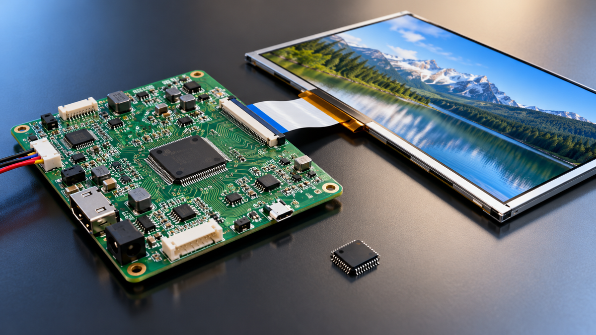
A display driver IC and a controller board are not two parts competing for the same slot. The driver IC writes pixel voltage onto the glass, and the panel maker bonds it there before the module ships. A controller board takes HDMI, DP or USB from your host, converts it to whatever the panel speaks, and builds the rail voltages and the backlight current.
So asking which one to buy is usually the wrong question. Order a finished module and the driver IC is already installed and already priced into the panel, leaving one decision, whether your host needs a board in front of it. Build up from bare glass and the driver ICs become your purchase, which makes the board the optional part.
The driver half of a 1024×600 panel is 3,072 source channels plus 600 gate channels. The board half is 4 rail voltages, 1 backlight current source and the pixel clock path. Moving to 1920×1080 grows the driver half 1.9× to 5,760 source channels, while the pixel clock jumps 3.3×, from 44.6 MHz to 148.5 MHz.
Volume splits the rest. Between 50 and 10,000 units a year the board is a buy. Past 10,000 units, owning the board design takes 1 PCB and 5 supplies off every unit, and driver ICs only become your purchase if you also take on the COG bonding the panel maker normally does.

The Layers Between Glass and Host
| Layer | Who supplies it | The number that matters |
|---|---|---|
| LCD glass and TFT array | Panel maker | 1024×600 means 614,400 pixels |
| Source and gate driver ICs | Panel maker, bonded to glass or film | 3,072 source channels plus 600 gate channels at 1024×600 |
| T-CON timing control | Comes with X-board panels, not with bare glass | Generates the 44.6 MHz pixel clock |
| Interface, power, backlight | Controller board | 4 voltage rails plus 1 backlight current source, 1 to 3 inputs |
A 7-inch 1024×600 module shows up with 4 source chips and 2 gate chips already bonded to the glass. Inside a TFT structure those chips sit on the same substrate as the pixel array, so their cost hides inside the panel price instead of your bill of materials.
Dropping the middle layer at 1,000 units means 1,000 fewer PCBs and 1,000 fewer 5-rail supplies. The same change removes one radiated emissions test, which sweeps 30 MHz to 1 GHz[1]. The 44.6 MHz pixel clock of a 1024×600 panel lands right inside that band.
Match the Interfaces and You Skip the Board
Parallel buses move a whole pixel per clock and serial links pack several bits into each differential pair. Wire count follows from that split, running 28 wires for RGB888, 10 for LVDS and 4 for SPI, so display interfaces differ by 7× in pin cost alone.
| Interface | Signal wires | Pixel clock or load at 60 Hz | What the host needs |
|---|---|---|---|
| SPI | 4 | 240×320 full refresh at about 32 fps with a 40 MHz SPI clock | Any MCU |
| 8080 parallel, 16-bit | About 20 | 240×320 goes past 60 fps | MCU with an external bus |
| RGB parallel, 24-bit | 28 | 33.3 MHz at 800×480, 44.6 MHz at 1024×600 | MCU with LTDC or LCDIF |
| LVDS single-link, 24-bit | 10 | 498 Mbps per pair at 1280×800 | SoC with an LVDS transmitter |
| LVDS dual-link, 24-bit | 18 | 520 Mbps per pair at 1920×1080 | Same, plus a second pair group |
| MIPI DSI, 4 lane | 10 | 4.5 Gbps per lane on D-PHY v2.1, 18 Gbps across 4 lanes[2] | SoC with DSI |
| eDP, 4 lane | 10 | 5.4 Gbps per lane on HBR2, 8.1 Gbps on HBR3[3] | SoC with eDP |
An RGB888 interface moves 24 bits per pixel in parallel, 18 wires more than LVDS, and the length-matching list drops from 24 traces to 4 pairs. A 7-inch ribbon also spends 28 of its 40 pins on signals, leaving 12 for power and ground.
LVDS carries 24 bits per pixel and each data pair moves 7 bits per pixel clock, which is where the LVDS interface 7:1 serialization comes from. 24 ÷ 7 = 3.43, so 4 pairs is the minimum, and at 18-bit color the sum is 18 ÷ 7 = 2.57, rounding to 3 pairs.
A 240×320 frame over the SPI bus is 153.6 KB. A 40 MHz clock turns that into 30.7 ms a frame, so 32 fps.
A 1920×1080 frame is 6.22 MB, or 373 MB every second at 60 Hz. Double-buffered 24-bit color needs 12.4 MB of frame buffer.
C-PHY sits on the same layer as D-PHY but encodes differently. Three wires form a trio, there is no separate clock line, and each symbol carries 2.28 bits[4]. The same 4 lanes drop from 10 wires to 9.
eDP runs HBR3 at 8.1 Gbps per lane. Across 4 lanes that is 32.4 Gbps raw, or 25.92 Gbps after 8b/10b. A 30-pin connector spends 8 pins on those 4 lanes, 2 on AUX, and 20 on power and ground.
Do the Pixel Clock Math Yourself
Pixel clock = total horizontal pixels × total vertical lines × refresh rate. For 1024×600 that gives 1184 × 628 × 60 = 44.6 MHz, and for 800×480 it gives 1056 × 525 × 60 = 33.3 MHz.
Blanking is the panel maker's call, so two 1024×600 panels from two vendors will not both use 1184 horizontal pixels.
A 1920×1080 frame takes 16.7 ms. Spread over 1125 lines that leaves 14.8 µs per line, of which the 1920 active pixels eat 12.9 µs and horizontal blanking keeps 1.9 µs.
| Resolution | Total horizontal | Total lines | Pixel clock | 24-bit bit rate |
|---|---|---|---|---|
| 800×480 | 1056 | 525 | 33.3 MHz | 798 Mbps |
| 1024×600 | 1184 | 628 | 44.6 MHz | 1.071 Gbps |
| 1280×800 | 1440 | 823 | 71.1 MHz | 1.707 Gbps |
| 1366×768 | 1466 | 798 | 70.2 MHz | 1.685 Gbps |
| 1920×1080 | 2200 | 1125 | 148.5 MHz | 3.564 Gbps |
Multiply the pixel clock by 24 and you have the 24-bit bit rate. Each LVDS pair moves 7 bits per pixel clock, giving 312 Mbps at 44.6 MHz, 498 Mbps at 71.1 MHz and 1,040 Mbps at 148.5 MHz.
Bit rate follows bit depth. A 1920×1080 panel at 60 Hz runs 2.673 Gbps at 18-bit, 3.564 Gbps at 24-bit and 4.455 Gbps at 30-bit, and the last of those matches the 10-bit-per-channel level ITU-R BT.2020 specifies for UHDTV[5]. Going from 18-bit to 30-bit adds 67%.
Raising the same 1024×600 panel from 60 Hz to 120 Hz moves the pixel clock from 44.6 MHz to 89.2 MHz. Every LVDS pair goes from 312 Mbps to 624 Mbps, which leaves 5% of headroom under the 655 Mbps mark.
How Far the Panel's Own Chips Get You
Panels carry 2 kinds of driver chip. Source drivers write the columns at 3 channels per horizontal pixel, and gate drivers scan the rows at 1 output per line.
1920×1080 packs 3.4× the pixels of 1024×600, yet it only needs 1.9× the source channels.
| Resolution | Source channels | With 960-channel parts | With 1440-channel parts |
|---|---|---|---|
| 800×480 | 2,400 | 3 chips, 2,880 channels | 2 chips, 2,880 channels |
| 1024×600 | 3,072 | 4 chips, 3,840 channels | 3 chips, 4,320 channels |
| 1280×800 | 3,840 | 4 chips, 3,840 channels | 3 chips, 4,320 channels |
| 1366×768 | 4,098 | 5 chips, 4,800 channels | 3 chips, 4,320 channels |
| 1920×1080 | 5,760 | 6 chips, 5,760 channels | 4 chips, 5,760 channels |
Channel counts round up to whole chips. A 1024×600 panel needs 3,072 channels, so 960-channel parts mean 4 chips for 3,840 channels and 768 idle channels, or 80% utilization.
The 1920×1080 panel needs 5,760 channels. Four 1,440-channel parts hit it dead on at 100%, while six 960-channel parts also hit it but add 2 chips to your bill of materials.
Channel counts per part come from vendor lineups rather than any standard. Source drivers commonly come in 720, 960, 1,152 and 1,440 channels. Gate drivers run 240 to 512 outputs. COG output pitch usually sits between 20 µm and 40 µm. Treat the chip counts above as a sizing estimate, and check the panel spec and the chip datasheet before you commit.
Gate lines need fewer parts. The 1,080 lines take 1,080 outputs, and three 512-output parts give 1,536 for 70% utilization.
Those 3,072 source channels at 30 µm pitch eat 92 mm of a 7-inch panel's 154.9 mm width, leaving 31 mm at each end for the border and the edge routing.
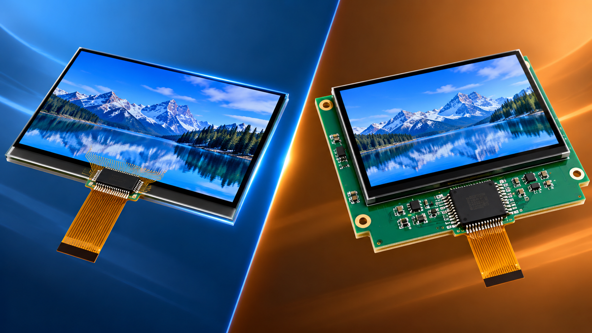
The panel maker bonds the source and gate chips to glass or film, which is what separates bare glass from a ready-to-drive COG LCD module.
Order a finished module and only segment and monochrome dot-matrix panels might arrive without driver chips on the glass. Order bare glass for a graphics panel and the bonding work lands on you. A segment display runs off 1 segment driver IC, and the common 4×40 part drives 160 segments over 2 I²C wires. Character panels are usually 16×2 to 40×4, and standard character LCD modules ship with that driver already mounted.
Pick Your Route
| Your situation | What to do |
|---|---|
| Panel interface is LVDS, eDP or MIPI and your host only has HDMI, DP or USB | Buy a controller board. A 1920×1080 eDP panel will not talk to an HDMI-only industrial PC |
| Volume between 50 and 10,000 units a year | Buy a controller board. Going custom adds another EMC sweep and another board revision |
| You need an OSD menu, brightness control, 2 or more inputs | Buy a controller board |
| You would rather not build the 4 rails and the backlight current source | Buy a controller board |
| Over 10,000 units a year | Design your own board. It takes 1 PCB and 5 supplies off every unit |
| You run COG bonding in house, or your panel maker ships bare glass | Buy the source and gate driver ICs and place them, then add a T-CON |
| You need custom timing, different rail voltages or an odd backlight | Go custom. Off-the-shelf boards ship with one fixed config |
| You want command mode plus panel self-refresh | Go custom. Only your own T-CON gets you there |
Host interface match and board ownership are the only 2 variables left. A custom display solution only pays back past 10,000 units a year, once the board stops being a catalog item.
The Power Rails and Backlight Nobody Budgets For
A 7-inch 1024×600 backlight usually runs 3 strings of 6 LEDs at 20 mA each. Forward drop comes to about 19.2 V, and with 2 V left for the current source the boost converter has to put out more than 21 V.
Three strings at 20 mA across 19.2 V come to 1.15 W. Bumping the output to 21 V makes it 1.26 W, so the current regulator absorbs the 0.11 W difference. The 1.15 W lights 0.0135 square meters of glass to 500 cd/m².
The panel itself wants VDD, AVDD, VGH and VGL, which is 4 rails. VDD sits around 10 mA and AVDD around 20 mA, while VGH and VGL stay under 1 mA each. Those 4 rails come to roughly 0.3 W against 1.26 W for the backlight.
VDD has to come up before AVDD, then VGH and VGL follow. The gap between them runs 0 to 10 ms depending on the panel spec. Get the order wrong and the screen shows streaks or goes blank white. Controller boards bake that sequence in, which is also why you cannot change it.
Run the Numbers on a 1080p Panel
Take a 1920×1080 panel at 60 Hz and 24-bit color. The pixel clock is 148.5 MHz, one frame is 6.22 MB, and the raw bit rate is 3.564 Gbps.
MIPI DSI on D-PHY v2.1 runs 4.5 Gbps per lane, so 2 lanes give 9 Gbps raw and roughly 8 Gbps once packet headers and checksums are accounted for, better than twice the 3.564 Gbps payload. A single lane gives 4.5 Gbps raw and about 4 Gbps usable, which still covers the payload with 12% to spare.
An LVDS link at this resolution puts 1,040 Mbps on every pair. TIA/EIA-644 suggested 655 Mbps back when it was written, and modern transceivers will do about 1 Gbps, but 1,040 Mbps eats nearly all the margin in the T-CON and the ribbon, so the practical answer is dual-link.
Dual-link drops each pair to 520 Mbps and takes the data pairs from 4 to 8. With one clock pair on top, wire count goes from 10 to 18.
eDP runs HBR2 across 2 lanes for 10.8 Gbps raw and 8.64 Gbps usable. HBR3 needs only one lane, where 6.48 Gbps is enough.
Most panels ship a 4-lane DSI connector even though 1080p60 uses only 2 of those lanes. The spare pair carries enough to push 120 Hz, which wants 7.128 Gbps at 24-bit color against roughly 16 Gbps usable from 4 lanes.
What to Put in Your Spec Sheet
- Resolution and pixel clock: 1280×800 is 71.1 MHz, 1366×768 is 70.2 MHz
- Interface type and lane count: DSI 4-lane, or a single LVDS link
- Backlight voltage and current: most 7-inch panels run 20 mA constant current at 19.2 V
- Power-up and power-down order: VDD, AVDD, VGH, VGL, 4 rails
- Operating temperature: wide-temp panels commonly cover −20℃ to 70℃
Those 5 lines match the fields a display selection guide sorts on, so filling them in first keeps you from sampling parts your host cannot drive.
Treat the rail ranges as rough guidance only. VGH sits somewhere between 15 and 20 V, VGL between −6 and −10 V, and AVDD between 9 and 15 V. Pull the real numbers from the panel spec rather than pasting a range into a purchase order.
Counting dead pixels by eye does not work. ISO 9241-307 sorts panels into 4 classes by how many defects they allow per million pixels.
| Class | Bright pixels | Dark pixels | Bad sub-pixels |
|---|---|---|---|
| I | 1 | 1 | 2 |
| II | 2 | 2 | 5 |
| III | 5 | 15 | 50 |
| IV | 50 | 150 | 500 |
The bad sub-pixel column is a simplification. The standard splits bright and dark sub-pixels into separate Type 3 and Type 4 limits. If you quote it in a contract, say which group you mean.
A 1024×600 panel holds only 0.614 million pixels. Class III gives about 3 bright pixels, 9 dark pixels and 31 bad sub-pixels, while Class I leaves bright and dark pixels 0.6 of an allowance each[6].
A 1920×1080 panel holds 2.07 million pixels, so Class III allows 10 bright, 31 dark and 104 bad sub-pixels. The 1366×768 panel at 1.05 million gets 5, 16 and 52.
Getting the class wrong by one step moves the bright-pixel tolerance 5×, dark pixels 15× and bad sub-pixels 25×.
Chinese acceptance runs through GB/T 18910.203-2021[7]. Published 2021-10-11 and effective 2022-05-01, it is identical to IEC 61747-20-3:2016[8].
GB/T 18910.61-2021 covers photoelectric parameters, while GB/T 18910.101-2021 and .102-2021 cover mechanical and environmental durability. Both took effect 2022-05-01. The generic spec got a new edition as well. GB/T 18910.11-2024 replaces the 2012 version, effective 2024-08-01, and it tracks IEC 61747-1-1[9].
Things People Mix Up
A Controller Board Is Not a T-CON
A T-CON handles timing only. A controller board also carries the interface conversion, the VGH, VGL and AVDD rails, and the backlight current source. Ask what T-CON a board uses and you have answered 1 of those 4.
The Resolution on the Label Is the Input Side
A board rated for 4K input can take a 4K signal. How many pixels it drives on the output side depends on the panel. Scale 1280×720 up to a 1920×1080 output and the pixel count multiplies by 2.25, then feed that into a 1024×600 panel and 70% of those pixels never light.
Newer Interfaces Aren't Automatically Better
D-PHY v3.0 runs 9 Gbps per lane, double the 4.5 Gbps of v2.1. A 1920×1080 panel at 60 Hz only wants 3.564 Gbps, which 2 lanes of v2.1 already cover at 8 Gbps usable. The extra 5.4 Gbps per lane buys nothing on the panel side, and it costs tighter impedance control on the flex.
Physical Layer Speed Comes With Overhead
8b/10b keeps 80%, 16b/18b keeps 89% and 128b/132b keeps 97%. HDMI 2.1 labels 48 Gbps and delivers 42.6 Gbps. HDMI 1.4 labels 10.2 Gbps and delivers 8.16 Gbps[10].
Common Questions
Why Do I Need a Board at All?
Something has to turn your host's signal into the panel's native interface and build 4 rails plus the backlight current. A controller board does both jobs on one PCB. When the host already emits the right interface and your own hardware supplies the rails, that PCB is redundant and 5 supplies come off the BOM.
Is a Driver IC the Same as a Driver Board?
No, and the two names cause most of the confusion. A driver IC is the chip that writes pixel voltage, bonded to the glass and paid for inside the panel price. A driver board is a PCB, and it means the same thing as a controller board.
Some vendors split those 2 labels, calling a pure interface converter a driver board and reserving controller board for a unit with an OSD and input switching. Check resolution, interface and backlight voltage rather than the label. A 1024×600 panel holds its 3,072 source channels and 600 gate channels in chip form, and the board holds none of them.
Can One Board Drive Any Panel Size?
No. The output interface is fixed at the factory, and an LVDS board cannot talk to an eDP panel. Even inside one interface you still match resolution, lane count, pinout and backlight voltage. A 1024×600 and a 1920×1080 panel both use LVDS and both might use a 30-pin ribbon, yet the pinouts can differ.
Can I Wire HDMI Straight Into an LVDS Panel?
No. An HDMI-to-LVDS board goes in between. If the panel is 1920×1080 you also need dual-link, and a single-link converter cannot carry it.
Does a Segment Display Need a Driver?
Yes. A single segment driver IC runs it, and static current sits in the µA range. Coin-cell products keep using them for that reason.
Do I Still Need a Board With DSI?
You do not, as long as the interfaces match. Check the pinout, the backlight voltage and the power-up order. Miss any of those 3 and you still need a small board to fix the rails and the timing.
Have a panel number and a volume in mind? Send the resolution, the interface type and lane count, the backlight voltage and current, and the power-up order from the datasheet. You get back a drive scheme, either a controller board or a direct connection to your host, plus the channel counts, rail currents and backlight driver sizing that fit it.
Laisser un commentaire
Ce site est protégé par hCaptcha, et la Politique de confidentialité et les Conditions de service de hCaptcha s’appliquent.