ILI9341 · graphics
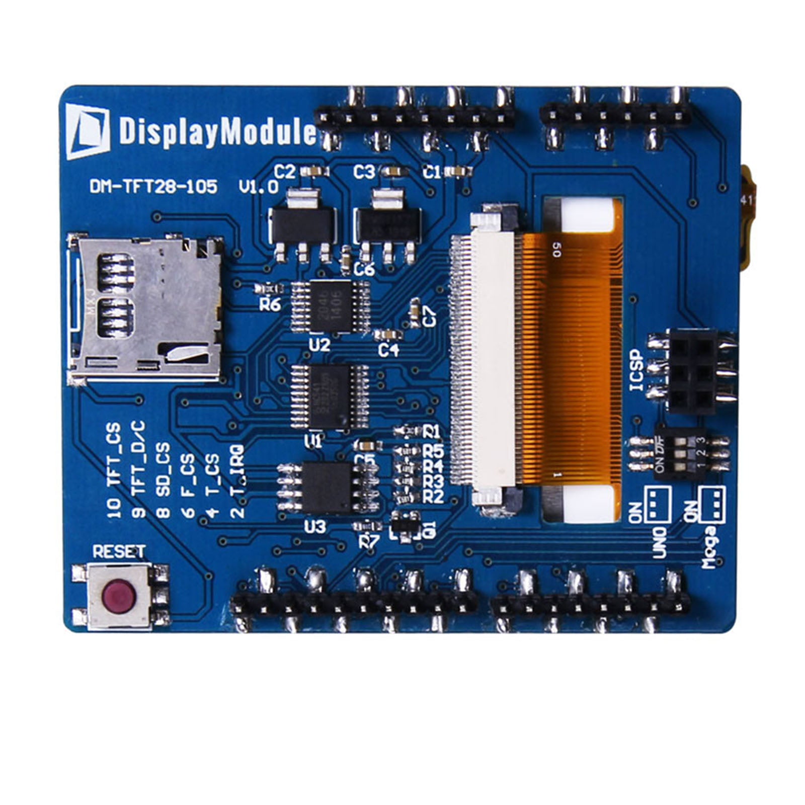
The display controller receives commands and pixel data for the 240 × 320 image. TFT_CS on D10 selects the display and TFT_D/C on D9 distinguishes command and data transfers.


Popular Products


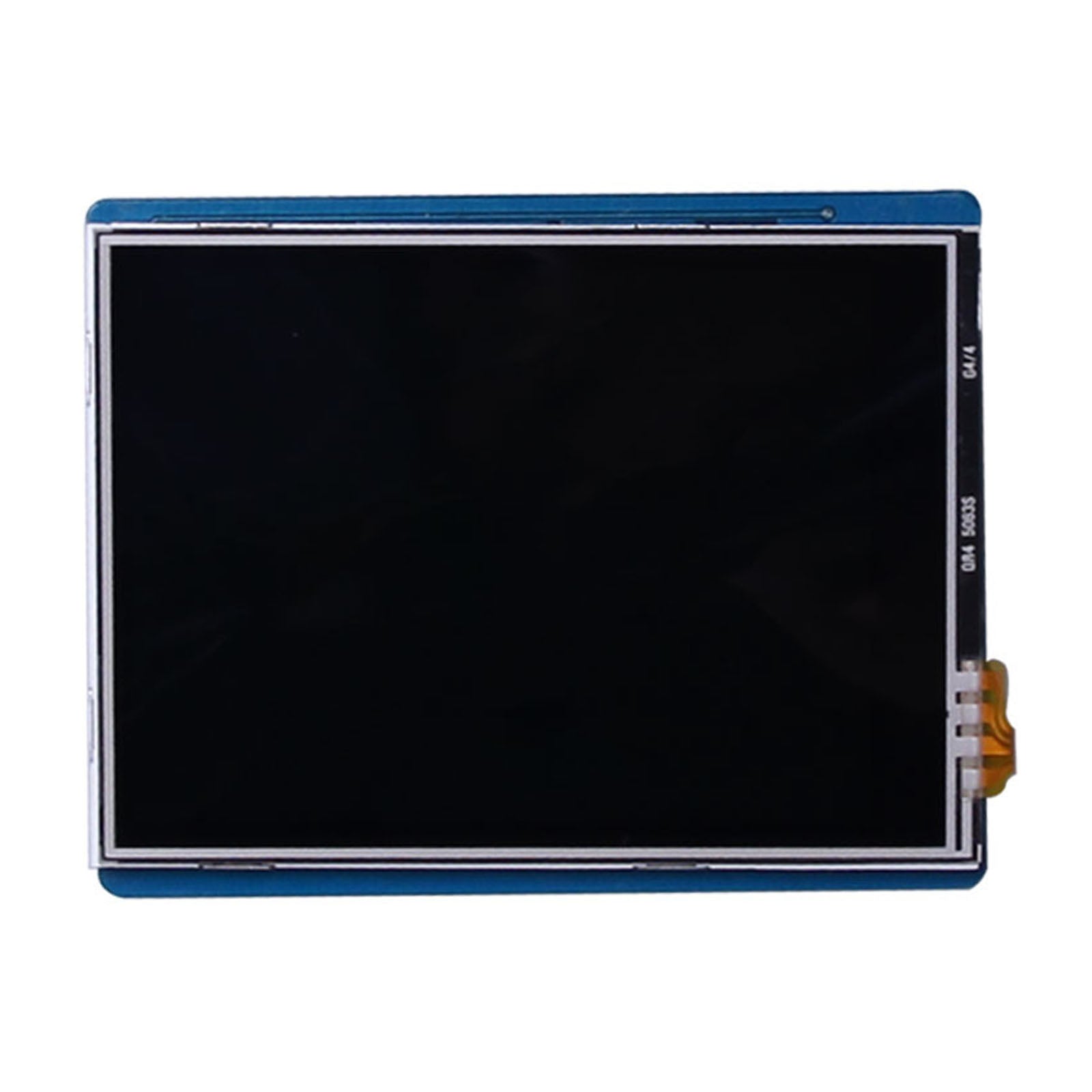
DM-TFT28-105
Colour graphics, resistive touch and local asset storage on one Arduino-header shield. DM-TFT28-105 combines a 240 × 320 ILI9341 display with an XPT2046 touch controller, microSD interface and 4 Mbyte flash.
A shared SPI bus serves the four peripherals. Select the header route for your host board and confirm its supply connection before assembly.
 + Click to enlarge
The shield combines graphics, touch measurement and two storage paths. Each peripheral has a distinct role in the user interface while sharing the SPI clock and data lines.
The display controller receives commands and pixel data for the 240 × 320 image. TFT_CS on D10 selects the display and TFT_D/C on D9 distinguishes command and data transfers.
The touch controller is selected by T_CS on D4. Its T_IRQ signal reaches D2, allowing the application to handle touch events separately from screen updates.
SD_CS on D8 selects the card interface. F_CS on D6 selects the onboard flash, providing separate access to removable and onboard data storage.
A shared bus requires coordinated transactions: the application selects the intended device and releases it before addressing another. The storage interfaces provide data for the application; they do not redraw the screen autonomously.
Shield connection reference →The rear switches select the SPI path. Switches 1–3 ON connect SPI through D11, D12 and D13; switches 1–3 OFF use the ICSP header. These routes support the UNO and Mega header arrangements described in the module guide.
The display, touch, microSD and flash chip-select signals connect to D10, D4, D8 and D6 respectively. D9 controls display command/data selection, while D2 carries the touch interrupt. These separate signals let the application coordinate the four SPI peripherals.
The electrical specification distinguishes the shield supply from the logic levels used on SPI and peripheral-control signals. This matters when the host processor uses a different I/O voltage.
The electrical table gives 5.0 V typical for the logic and analog supplies. This is the operating range, separate from the absolute-maximum entries.
The specified low-level input range applies to MOSI, MISO, CLK, TFT_CS, TFT_D/C, SD_CS, F_CS, T_CS and T_IRQ as listed in the module guide.
These signal limits describe the module-side electrical interface. The host’s own input-voltage tolerance must also be respected.
For a 3.3 V host, the supply route and both directions of the SPI connection need to match the host board. Header compatibility alone does not establish the electrical compatibility of every board revision.
Electrical and signal-level reference →| Parameter | Specification |
|---|---|
| Product model | DM-TFT28-105 |
| Display size | 2.8 inch |
| Resolution | 240 × 320 pixels |
| Display connection | SPI |
| Controller / panel | ILI9341; XPT2046 touch controller |
| Display colours | 262K |
| Touch configuration | Resistive |
| Supply | 4.8–5.2 V; 5.0 V typical (electrical table; confirm revision for 3.3 V supply) |
| Luminance | 240 cd/m² typical |
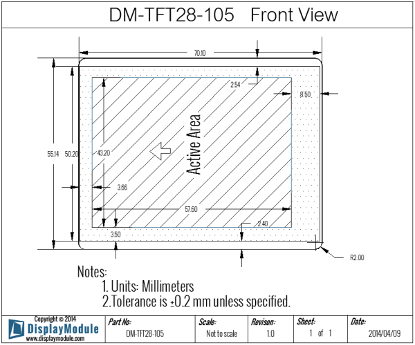
| Mechanical reference | 70.10 × 55.14 mm; 71.10 × 55.14 mm with SD card |
The W25Q32BV flash provides 32 Mbit, equivalent to 4 Mbyte, of onboard storage. It can hold images, fonts, calibration data and logs, alongside the removable microSD storage interface.
The flash is intended for data storage rather than program-code storage. Its SPI connection shares CLK, MOSI and MISO with the other peripherals, so the host application controls access through F_CS.
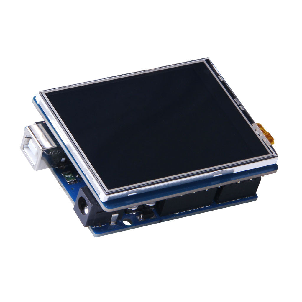
The shield, inserted card and host headers form one installed assembly.
The module measures 70.10 × 55.14 mm, increasing to 71.10 × 55.14 mm with an SD card inserted. Leave access for the intended card-handling arrangement.
Use the 4 Mbyte flash for onboard data and microSD for removable storage. The host reads those assets and sends the required pixels to the display.
Identify the host’s SPI route and supply connection together. Board-header compatibility does not resolve the guide’s differing 3.3 V and 5 V supply descriptions.
The optical specification gives separate viewing directions and a response-time condition. They describe how this particular 2.8-inch display presents information at its intended viewing position.
These are typical viewing-angle values. The typical bottom viewing angle is 57°, so the viewing envelope is not symmetrical.
This is the specified optical response time. It is separate from the time required to transfer a screen image over SPI.
Contrast ratio and 240 cd/m² typical luminance are panel characteristics. They do not specify the effect of an additional enclosure window.
For an installed interface, the screen orientation and expected viewing position can be considered alongside the application’s redraw rate. Touch acquisition and display updates remain separate host tasks.
Optical-specification reference →Switches 1–3 ON route SPI through D11–D13, the usual UNO arrangement. OFF selects the ICSP route used by Mega boards. The guide notes that UNO R3 supports both routes; check the actual headers fitted to a compatible board.
Initialize TFT_CS, T_CS, SD_CS and F_CS high, then select the intended peripheral for each transaction. Their header pins are D10, D4, D8 and D6 respectively. The touch interrupt uses D2; display command/data selection uses D9.
Confirm the board revision and power connection first. The guide advertises 3.3 V and 5 V input compatibility, while its electrical table lists 4.8–5.2 V supply operation. SPI input-high limits are listed separately at 3.0–5.0 V, so signal voltage and supply voltage need separate checks.
For DM-TFT28-105 setup assistance, provide the host-board model, the positions of switches 1–3 and whether SPI uses D11–D13 or ICSP. Include which of the display, touch, microSD and flash peripherals your application uses.
When requesting samples, identify the intended supply and board revision. Allow for the 71.10 mm module dimension with a card inserted, and include your quantity and removable-storage requirements in the quote request.
Use the shield guide for Arduino headers, SPI routing switches and electrical limits. The ILI9341 and XPT2046 PDFs describe the image and touch controllers; the mbed and UTFT links provide software guides.