



Embedded IPS Display Modules | Low Power & Compact Form Factor
In an embedded product, two numbers decide whether an IPS module fits: the average current it draws over a realistic duty cycle, and the millimetres it adds to the stack. Peak brightness and colour gamut matter less, because a battery-powered device spends most of its life showing a dim interface, not a photograph. Both numbers can be estimated before a purchase order and verified on a sample.
Power is a budget, not a single figure
An IPS module's consumption is the sum of four parts: the backlight, the driver IC, the panel's own capacitive load, and any touch controller. The backlight dominates — typically the majority of the total at useful brightness levels, because LCD is a shutter over a light source rather than an emitter.
That has a practical consequence for specification. A module quoted at a single "typical" current at maximum brightness tells you almost nothing about the battery life of a product that runs at 30% brightness for 90% of the time. The useful figure is current at the operating brightness, plus the standby current, plus the time spent in each state.
Where the power actually goes
The backlight. LED current scales roughly with luminance, but efficiency falls as drive current rises. Doubling brightness typically costs more than double the LED power, and it also raises junction temperature, which shortens lifetime.
Optical losses. Every layer between the LED and the eye loses light: the light guide, diffuser, prism sheets, polarisers and colour filter. Transmittance varies substantially between module designs, which is why two modules of the same size and brightness can draw noticeably different power.
The driver. Quiescent current in the driver IC and the source/gate drivers becomes significant at low refresh rates and in sleep states, where it can be the largest single contributor.
Touch and interfaces. A capacitive touch controller scanning continuously can add more than the panel's own logic. Its scan rate and sleep behaviour are worth checking separately.
Estimating battery life before you commit
The arithmetic is straightforward once the states are known. Take the battery capacity in mAh, multiply by the nominal voltage to get milliwatt-hours, then divide by the average power drawn across the duty cycle. Average power is the sum of each state's power multiplied by its share of the time.
Two corrections are usually necessary. Regulator losses between the battery and the backlight sit in series, and a boost converter driving a high-brightness backlight can lose a meaningful fraction of its input. And the brightness users actually select is often below the maximum, so measure at the realistic setting rather than the headline one.
Working through a realistic budget
Take a product with a 2.4-inch panel, an interface shown at 30% brightness for most of the day, and a screen that sleeps between readings. The budget has four lines: backlight current at 30%, driver quiescent current with the display on, touch scan current, and the sleep current that applies most of the time.
The counter-intuitive result is usually this: the sleep and idle currents, not the backlight, dominate a device that spends its life waiting. A module whose backlight is efficient but whose driver draws several milliamps at idle can lose to a module with a slightly hungrier backlight and a proper sleep-in mode. That is why the standby figure belongs in the same table as the operating figure.
Two design levers move the budget more than component selection. Reducing the fraction of time in the brightest state — by dimming, by using dark interface elements, or by switching the display off between readings — usually beats swapping modules. And driving the backlight from a regulator with good efficiency at low duty cycles avoids losing a large share of the energy before it reaches the LEDs.
Compact form factor means the whole stack
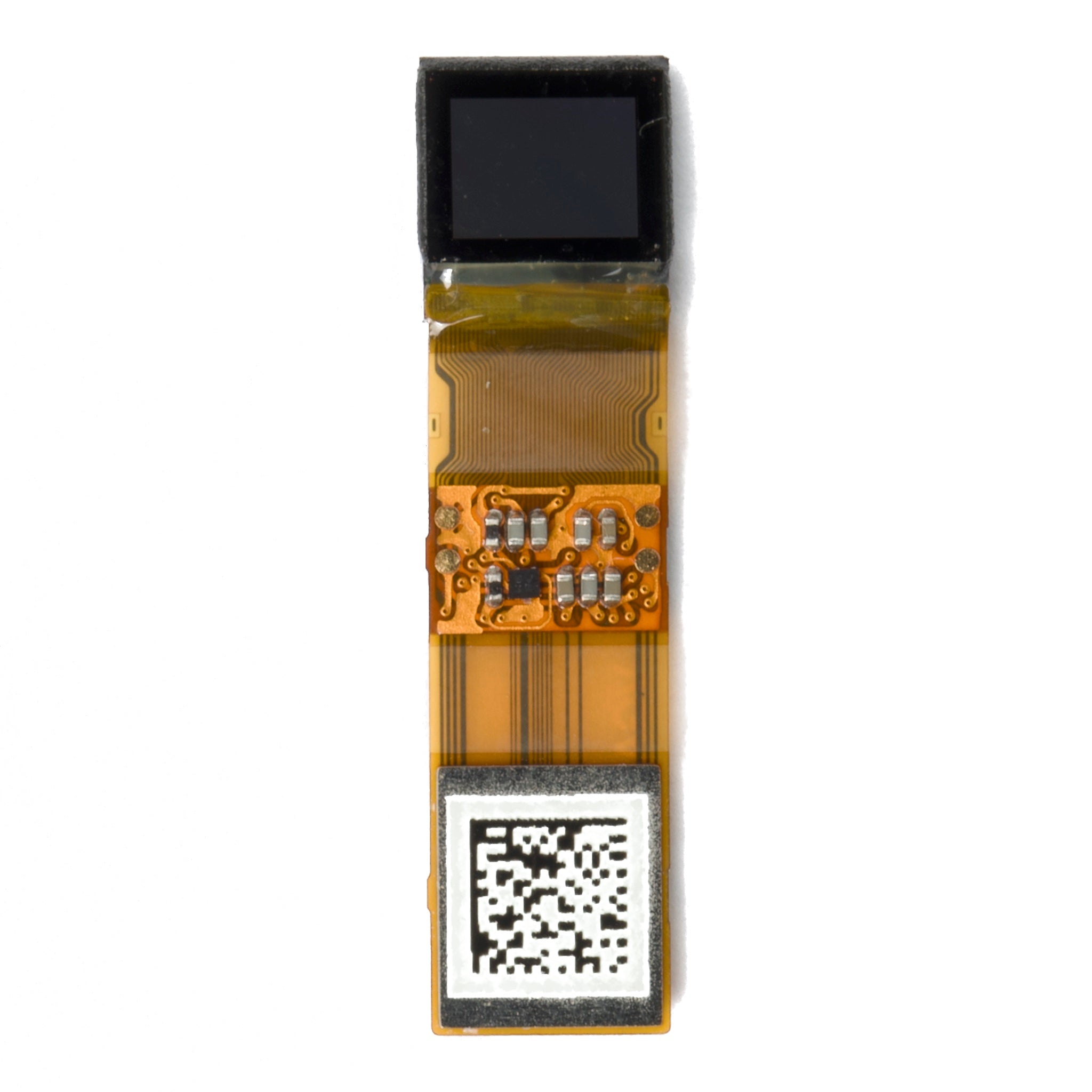
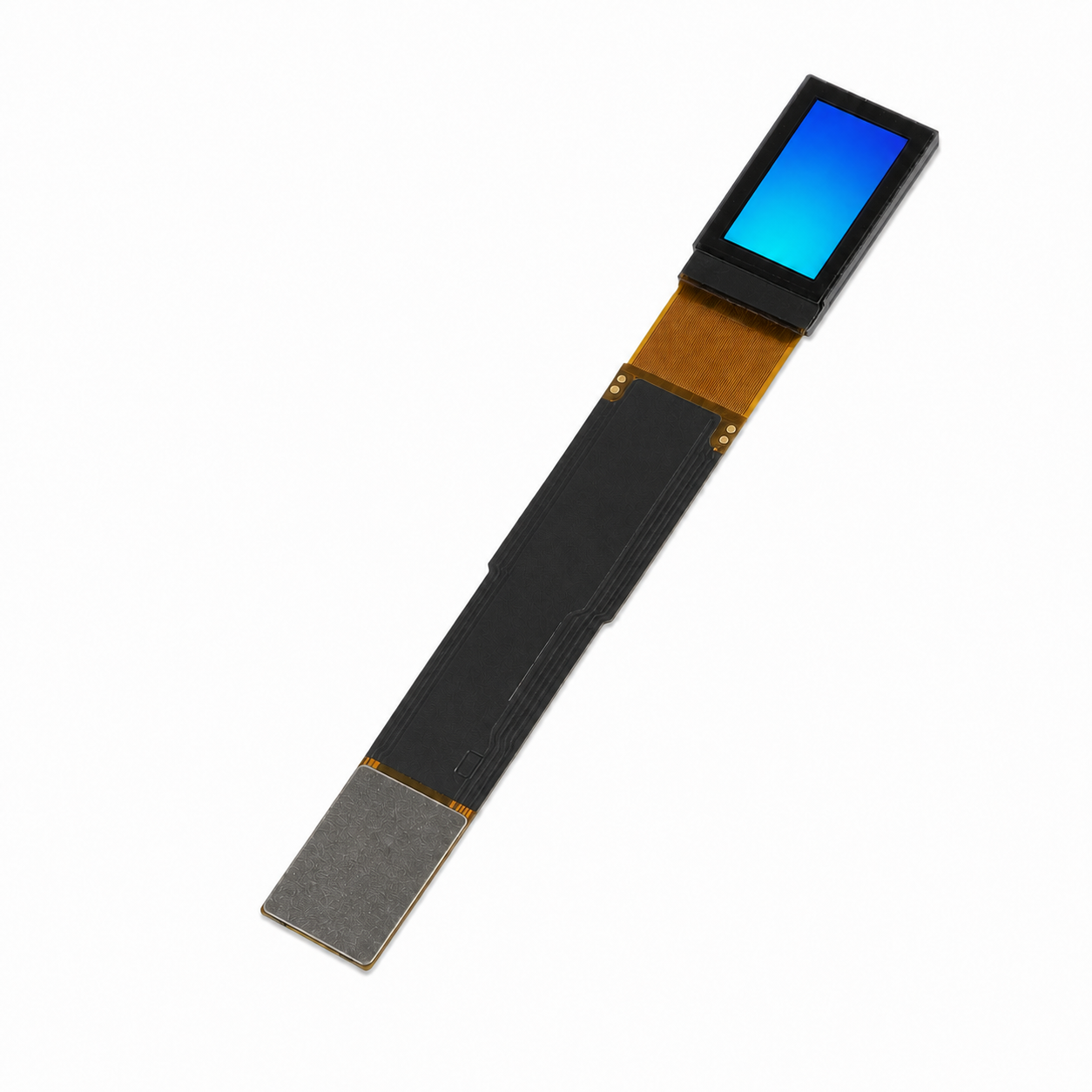
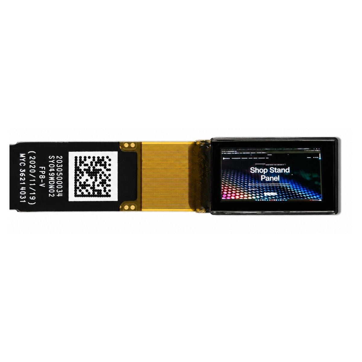
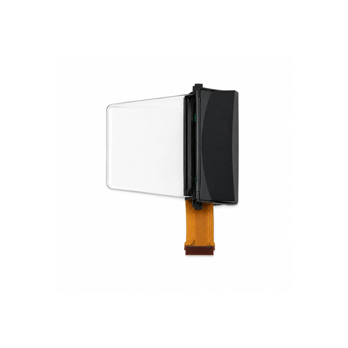
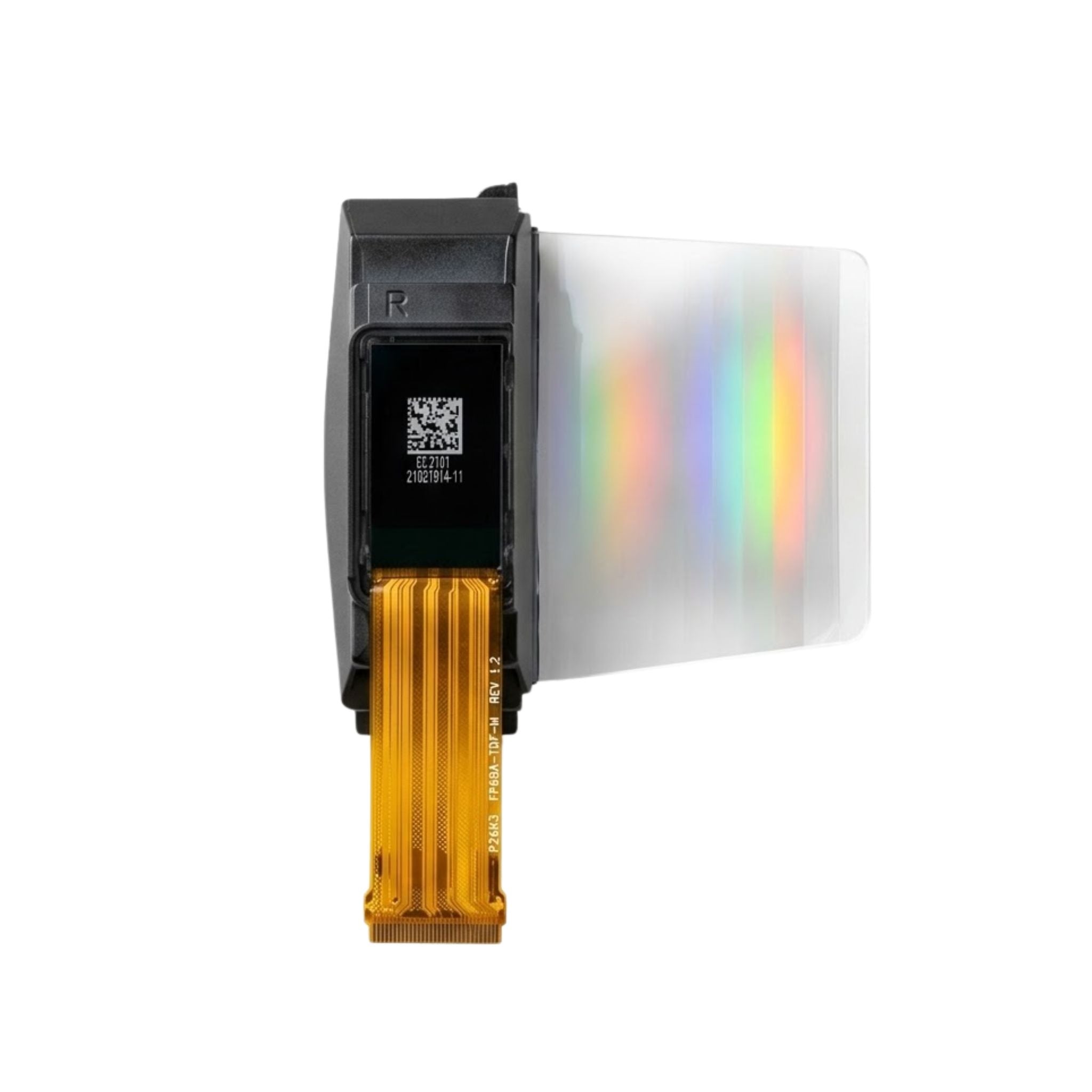
The thickness that matters is not the panel's, it is the assembly's. A module's stack typically includes the LCD cell, the backlight with its light guide and films, an optional touch sensor and cover glass, plus the FPC and its connector. Sub-3 mm assemblies exist, but they are usually achieved by removing layers — an air-gap-free optical bonding, a thinner light guide, or an on-cell touch sensor instead of a separate one.
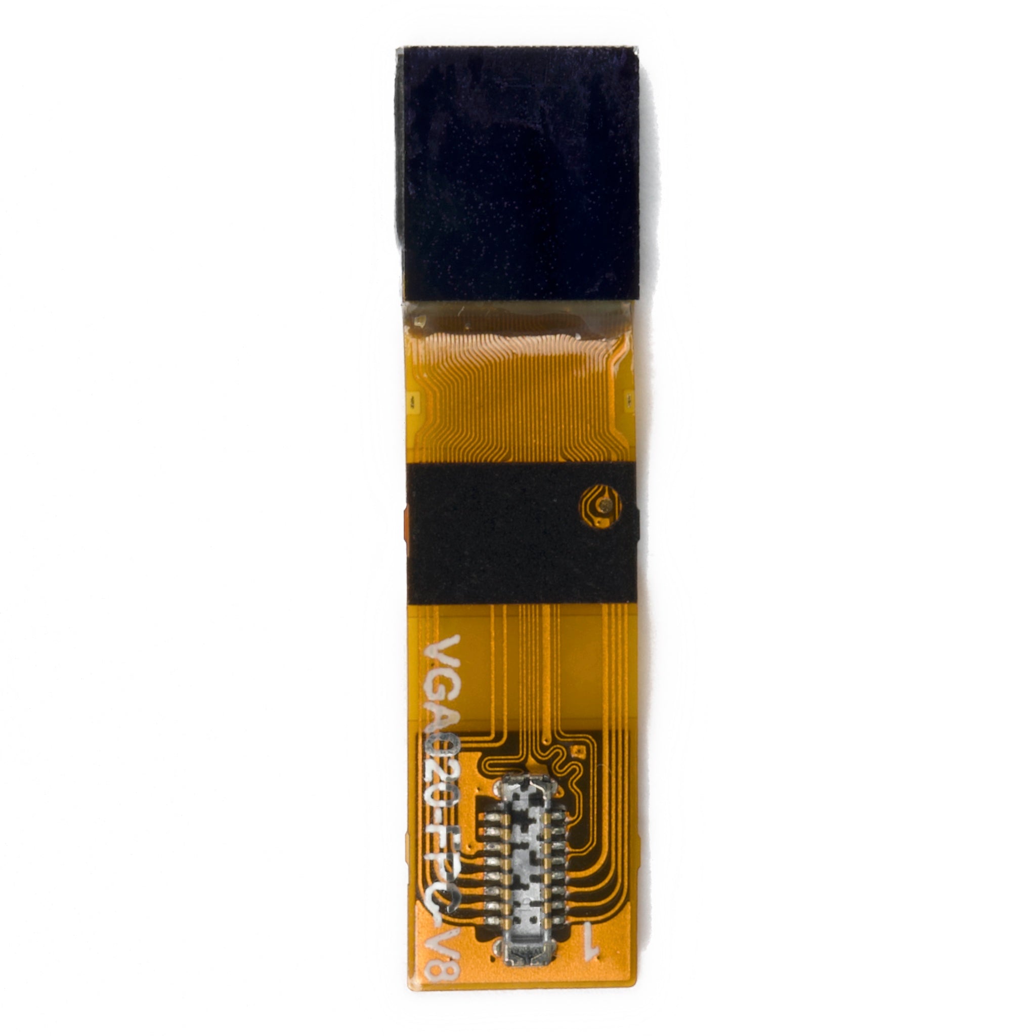
Three mechanical details cause most integration surprises: the connector height above the PCB, the minimum bend radius of the FPC, and the tolerance stack between the panel and the enclosure opening. Each needs to be fixed before the mechanical design freezes, because changing any of them later usually means changing the PCB as well.
Interfaces that match embedded controllers
Interface choice follows from resolution, colour depth and frame rate. SPI and 8-bit MCU interfaces are practical for small panels at modest frame rates; RGB parallel, MIPI DSI and LVDS become necessary as resolution or refresh rate rises. For a battery-powered product, the interface also sets a power floor: a parallel RGB link running continuously costs more than an SPI link that is idle between updates.
The drive mode matters as much as the bus. Partial refresh and sleep-in display modes let the controller update a small region or hold a static image with the interface idle, which is usually where the biggest battery savings are found.
Heat and lifetime in sealed enclosures
An IPS module in a sealed plastic case has no convection path. The backlight's waste heat raises the panel temperature above ambient, and at high brightness the difference can be significant. Two consequences follow: brightness may need to be derated at elevated ambient temperature, and the backlight lifetime quoted at room temperature will not hold inside a hot enclosure.
The specification to ask for is the derating curve — luminance versus ambient temperature — rather than a single brightness figure. If the product must run in direct sun, that curve decides whether a 1000-nit module is usable or whether the design needs thermal management first.
What to specify
- Current at the operating brightness, not only at maximum, and standby current with the interface idle.
- Assembly thickness with the touch and cover-glass options you intend to use.
- Connector type, height and FPC bend radius, with a drawing.
- Brightness derating versus ambient temperature.
- Backlight lifetime defined as hours to a stated fraction of initial luminance.
- The measurement basis for luminance and contrast, standardised in ISO 9241-307[1].
Compact IPS modules for wearables, handhelds and IoT devices are listed in the IPS display collection, including round and square formats; industrial housings and wider temperature ranges are covered by the industrial display range.

For embedded products, judge an IPS module on average current at the operating brightness and on assembly thickness with the options you will actually use. Both are estimable before ordering and measurable on a sample, and both matter more than the peak figures on the first page of the datasheet.
References
- ISO 9241-307:2008 — Ergonomics of human-system interaction — Part 307: Analysis and compliance test methods for electronic visual displays. International Organization for Standardization. https://www.iso.org/standard/40102.html
Read more
The IPS display module tailored for industrial use excels in durability and a wide temperature range , built to thrive in harsh settings like factory.
Choose IPS modules by aligning size (7–10” industrial, larger consumer), resolution (≥FHD/1920x1080 for clarity, 4K/3840x2160 pro), and interface.
Leave a comment
This site is protected by hCaptcha and the hCaptcha Privacy Policy and Terms of Service apply.