



Extending IPS Module Lifespan | Heat Dissipation & Voltage Tips
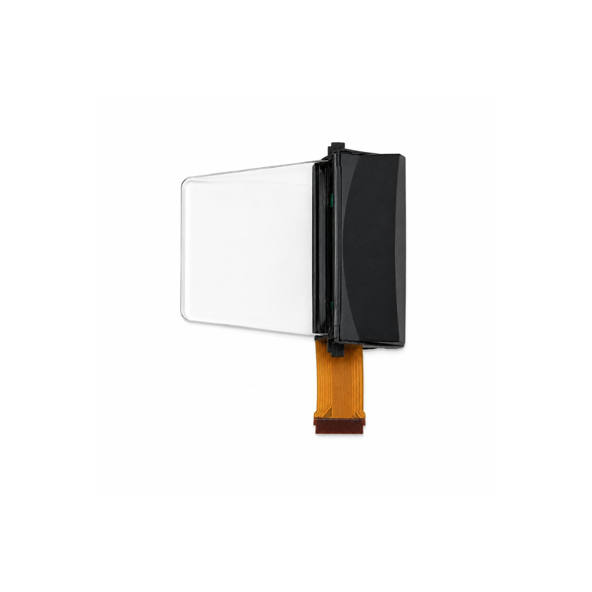
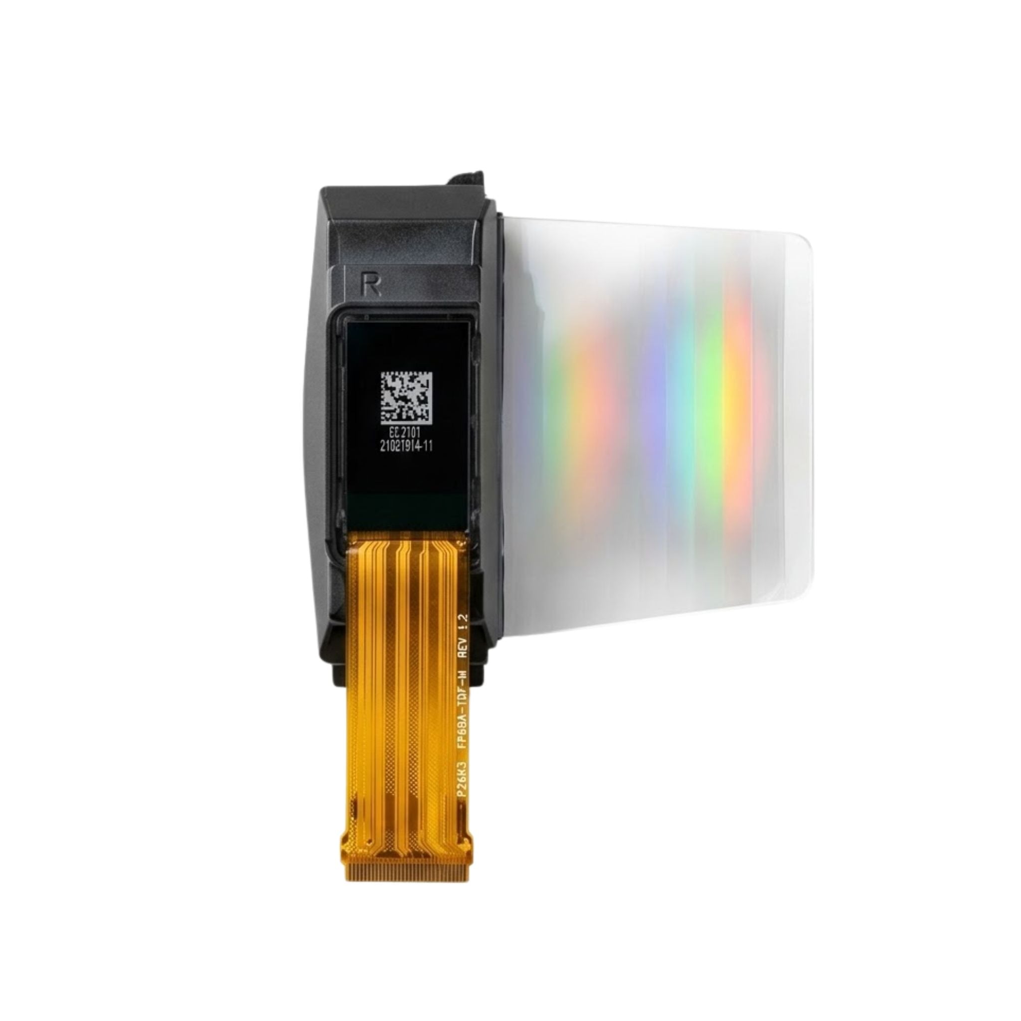
An IPS module rarely fails because of the liquid crystal. Life is set by the LED backlight, the driver electronics and the polarisers, and all three age faster when heat and supply voltage drift outside the datasheet window. Keeping the LED bar and driver IC cool, and feeding the module a regulated supply inside its rated range, is what separates a five-year module from a fifteen-year one.
Where the heat comes from
Almost all waste heat in a small IPS module comes from two places: the LED backlight and the driver ICs on the source board. The liquid crystal layer itself dissipates very little, because it is driven as a capacitive load with microamps of current. The backlight dominates, a point that has shaped every generation of flat-panel design since the thin-film transistor array became practical[2]. Light is generated by LEDs driven at constant current, and every optical loss between the LED and the front polariser — the light guide, the diffusers, the brightness enhancement films, the colour filter — turns into heat inside the stack.
A high-brightness module running at full output can put more heat into a five-inch assembly than the host device produces. That heat has nowhere to go except through the back of the module, and if the mechanical design leaves an air gap there, the LED junction temperature climbs while the enclosure surface still feels cool.
Two temperature numbers, not one
Datasheets quote an operating range and a storage range, and they are not interchangeable. The operating figure usually refers to a defined reference point — the panel surface, or a marked spot on the FPC — not to the air inside the enclosure. A module rated for 70 °C ambient is not rated for a 70 °C panel surface with 70 °C air behind it.
The failure that arrives first is rarely dramatic. Wide-temperature liquid crystal mixtures still slow down as they approach the low end of their range, and polarisers yellow and shrink at the top end long before anything burns out. If the application runs near the upper limit, ask the supplier which reference point the rating uses and how much margin the polariser has.
Measure before designing a heatsink
Thermal design starts with four readings: ambient air in the enclosure, panel surface, LED bar, and the driver IC. Attach fine thermocouples, close the unit, run it at the brightness the product will actually use, and wait for the readings to flatten — usually half an hour or more, because the thermal mass of the housing is large. A reading taken after five minutes describes the housing, not the module.
Record the optical conditions too, since a luminance reading means little without them[1]. Repeat the measurement at the highest expected ambient temperature, or in an oven if the product is specified for one. The gap between the LED bar reading and the datasheet limit is the budget you have to spend on mechanical changes.

Conduct heat out, then ventilate
Heat leaves a module through its mechanical interface. A thermal pad or gap filler between the rear of the module and a metal chassis does more than any fan, because it converts an air gap into a conduction path. Keep the pad thin and consistent in thickness, clamp it evenly with screws at the corners rather than in the middle, and avoid stacking several pads to reach a gap.
Convection is the second step. Vents sized generously relative to the enclosure surface, positioned low on one side and high on the opposite side, allow a chimney effect without moving parts. A fan should be the last resort, because it introduces a bearing that will fail, a filter that will clog, and dust that will settle on the surfaces you were trying to cool.
Supply voltage and inrush
Most modules take 3.3 V or 5 V logic plus a separate backlight rail. Treat the two as separate design problems. The logic rail tolerates a modest window around its nominal value; the backlight rail does not, because LED current rises steeply with forward voltage. Driving an LED string from a fixed voltage rail with a series resistor makes brightness and heat both a function of temperature, which is the wrong coupling.
Use a current-regulated driver, check the inrush at power-up and at hot-plug, and add bulk capacitance close to the connector. Long cables between the supply and the module add inductance and series resistance; at switch-on the module can see a dip deep enough to reset the driver or latch the display into an abnormal state.
Dimming without cooking the LEDs
Many modules dim by pulse-width modulation, switching the backlight on and off at a frequency above the eye's flicker threshold. Others reduce the LED current directly, and some mix the two. The distinction matters for thermal life. During the on-time of a PWM waveform the LEDs still run at full current, so the junction sees the same peak power and the same peak temperature; only the average falls. Reducing the current lowers the junction temperature itself.
Where the application allows it, capping maximum brightness is the cheapest reliability measure available. Very few products need the last ten percent of output, and that last ten percent is where the LED bar runs hottest. If PWM is required for colour stability, keep the frequency high enough that camera-based systems and sensitive users do not see banding.
Sealing, dust and condensation
Dust on a heatsink behaves like a blanket. In a plant with cement, flour or carbon black in the air, a visible layer builds up within weeks and the thermal path degrades quietly. Filters help only if someone replaces them; a sealed enclosure with a conduction path to an external surface avoids the problem entirely.
Sealing introduces the opposite risk. A gasket that keeps dust out also traps moisture, and a module that cycles between warm and cold will condense on the coldest surface inside the housing. Desiccant packs, a breathable membrane vent, or conformal coating on the FPC and connector area are the usual answers. Reapply torque to gasket screws at service intervals, because elastomer compression set is slow but real.
A maintenance routine worth the labor
Quarterly inspection catches most age-related problems early. Re-measure the four temperatures and compare them with the commissioning record; a rise of a few degrees with unchanged settings points to dust, a dried thermal pad or a fan losing speed. Check connectors for fretting and discolouration, look for browning at the edge of the polariser, and verify that brightness at a fixed setting has not dropped noticeably. Compare against the baseline rather than against a feeling.
What to put in the purchase specification
Ask for wide-temperature liquid crystal and polariser grades, LED binning and lumen-maintenance data at the drive current you will use, the driver IC's rated junction temperature, and the thermal interface material specified for the assembly. Request the test report for the conditions you actually care about, not a generic summary, and confirm that the module's rated reference point is stated on the drawing.
For applications where the enclosure is sealed and the ambient is high, a industrial display module built with these grades costs more upfront and far less over the product's life. Where the design is open-frame and ventilated, a standard IPS module with a proper thermal pad often meets the same target.
Bottom line
Lifespan is a thermal and electrical budget, not a specification you buy. Measure the four temperatures in the real enclosure, conduct heat into metal before adding a fan, drive the backlight with current regulation, and cap brightness where the product allows it.
References
- ISO 9241-307:2008 — Ergonomics of human-system interaction — Part 307: Analysis and compliance test methods for electronic visual displays. International Organization for Standardization. https://www.iso.org/standard/40102.html
- Hilsum, C. (2010). Flat-panel electronic displays: a triumph of physics, chemistry and engineering. Philosophical Transactions of the Royal Society A, 368(1914), 1027–1082. https://doi.org/10.1098/rsta.2009.0247
Read more
IPS modules ensure stable images with 178° wide viewing angles (minimal distortion) and ΔE < 2 color accuracy (industry benchmarks), minimizing color.
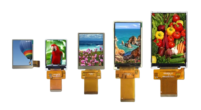
Custom TFT screens can precisely match performance requirements, such as industrial-grade wide temperature range (-30℃ to 80℃) and high brightness (1000.
Leave a comment
This site is protected by hCaptcha and the hCaptcha Privacy Policy and Terms of Service apply.