


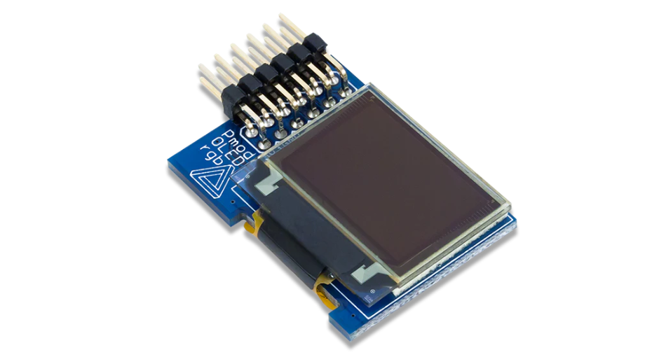
How to Choose a PMOLED | Key Specs, Interface Options
It is recommended to purchase modules under 3 inches with a resolution of 128×64.
Use 4-pin I2C when I/O is limited, and select SPI for high-speed requirements.
Make sure to confirm that brightness exceeds 100 nits and match with SSD1306 drivers to ensure compatibility.
Key Specs
PMOLED selection must match physical dimensions with the capabilities of the Driver IC.
Mainstream resolutions are concentrated in the 64x32 to 256x64 range.
Due to the limit of the 1/64 Duty cycle driving method, it is difficult to make them large.
Driver ICs like SSD1306 or SH1106 are universal standards, supporting 400kHz I2C or 10MHz SPI interfaces.
Electrical design needs to distinguish between the 1.65V-3.3V logic voltage and the 7V-15V panel driving voltage (VCC).
Regarding optical parameters, brightness is usually 100-200 nits, but lifespan varies significantly: blue materials typically decay to 50% within 15,000 hours, while yellow materials can last over 50,000 hours.
Size and Resolution
Limitations of Passive Driving
To light up 64 rows of pixels, the driver must sequentially light up row 1, row 2... up to row 64 in an extremely short time, and then quickly cycle back to row 1.
- Duty Cycle: For a 128x64 resolution, each row of pixels is powered and emitting light for only 1/64 of the time within a refresh cycle.
- Instantaneous Brightness Requirement: For users to perceive an average brightness of 100 nits, the pulse brightness of the pixel at the moment of power-on must reach 6400 nits or even higher.
- Physical Bottleneck: If one attempts to make a 320-row PMOLED, the duty cycle becomes 1/320. This would require extremely high instantaneous voltage (possibly exceeding 20V) and current, causing the organic material to age rapidly, overheat, or even break down.
Therefore, the vertical resolution of PMOLEDs on the market mostly stops at 64 rows or 128 rows, and the physical diagonal size rarely exceeds 3.0 inches.
Most Common Specifications
Between 0.91 inches and 2.42 inches, there are several industrially recognized "standard modules."
0.96 inch (128x64)
This is the general-purpose specification with the largest shipment volume, almost synonymous with DIY electronics and low-cost meters.
- Active Area: Approximately 21.74mm x 10.86mm.
- Pixel Pitch: Approximately 0.17mm x 0.17mm.
- Visual Effect: At a viewing distance of 30cm, pixel dots are almost invisible. This screen is suitable for displaying 4 lines of small text (16-20 English characters per line) or a complex QR code.
- Controller: Most are paired with SSD1306 or SH1106.
0.91 inch (128x32)
This "bar-shaped" screen removes half the rows and is often used in smart bands, USB Keys (U-Keys), or handle displays for 1U server racks.
- Physical Advantage: The height is usually only half that of a 0.96-inch screen, making it very suitable for slender PCB layouts.
- Driving Advantage: Since there are only 32 rows, the duty cycle is 1/32. This makes it brighter than a 128x64 screen at the same voltage, or allows for a lower driving voltage at the same brightness, which is beneficial for extending lifespan.
Screens Above Two Inches
When the size expands to over 2.0 inches (such as 2.42 inches or 2.7 inches), the resolution usually remains at 128x64.
- 2.42 Inch Module: Its pixel pitch expands to about 0.43mm. Careful observation reveals a distinct "screen door effect" (black gaps between pixels).
- Driver IC Change: The SSD1306 commonly used in small screens may have insufficient current driving capability for large pixels. 2.42-inch modules typically use the SSD1309. The SSD1309 supports higher drive currents and is compatible with most of the SSD1306 instruction set, but the boost capacitor value in the peripheral circuit needs to be increased.
- Application Scenarios: This large-pixel screen is suitable for industrial meters or cash register customer displays viewed from a distance, but not for close-up reading of fine text.
High-Density Exceptions
Although rare, there are high-end PMOLEDs on the market that break the 128x64 limit, mainly used for audio equipment or high-end measuring instruments requiring extreme precision.
- 256x64 Resolution: Common sizes are 2.08 inches or 2.23 inches.
- Grayscale Display: These screens are usually paired with the SSD1322 driver. The SSD1322 not only supports more columns but also supports 4-bit grayscale (16 Grayscale). Each pixel has not just "on/off" states but 16 brightness levels, allowing for the display of delicate black-and-white images or anti-aliased fonts.
- Data Bandwidth: The pixel count of 256x64 is doubled, and with 4-bit grayscale, each pixel requires 4 bits of data. The data volume required to refresh a frame is 8 times that of a standard monochrome 128x64 screen (256 x 64 x 4 bits vs 128 x 64 x 1 bit). Using an I2C interface will result in noticeable screen refresh lag; it is recommended to use the SPI interface.
Circular and Special Screens
With the rise of wearable devices, circular PMOLEDs are gradually entering the field of view of engineers.
- Non-Rectangular Mapping: The video RAM (GDDRAM) inside the Driver IC (like SSD1306) remains rectangular.
- Example 1.13 Inch Circular Screen: The physical resolution might be 96x96, but during actual driving, you need to write data to a 128x64 or 96x16 memory area and set the IC's "Segment Remap" and "Common Offset" parameters to map the image correctly into the circular area.
- Software Processing: When writing the GUI, you need to avoid the "dead zones" in the four corners, which increases the difficulty of UI layout.
Driver Chip Configuration
Choosing Solomon or Others
The PMOLED driver IC market is almost monopolized by Solomon Systech, but there are subtle and potential pitfalls between different models.
-
SSD1306 (Industry Standard):
This is currently the controller with the most resources and widest application. Its on-chip memory (GDDRAM) is exactly 128 columns x 64 rows (128x64 bits). Most open-source libraries (such as Adafruit_SSD1306, U8g2) are written based on this. If your screen resolution is 128x64 or 128x32, this model is the first choice. -
SH1106 (Cheap but Troublesome):
A compatible chip launched by Sino Wealth, often used in low-cost modules. Its memory is actually 132x64.- Offset Issue: Many engineers burn SSD1306 driver code directly into it and find that the screen content is shifted 2 pixels to the right, or there is a 2-pixel wide strip of noise on the left.
- Solution: This is because the SH1106 memory is wider than the physical pixels of the screen, and usually, the screen glass is connected to the center of the Driver. When writing the driver, you need to set the starting Column Address to 0x02 instead of 0x00.
-
SSD1315 (Newer Alternative):
An upgraded version of the SSD1306, mainly improving electrostatic discharge (ESD) protection and anti-interference capabilities. Its instruction set is almost completely compatible with the 1306, and it can usually be a direct replacement without modifying software.
Handling Voltage Charge Pump
OLED pixels require a high voltage of 7V to 15V (VCC) to emit light, while handheld device batteries are typically only 3.3V or 5V.
The configuration of the charge pump inside the Driver IC determines whether you need to add an extra boost chip on the PCB.
-
Internal Generation Mode:
Most modules under 0.96 inches enable this mode.- Configuration Method: Send command 0x8D followed by 0x14 to enable the charge pump.
- Hardware Requirements: A low ESR ceramic capacitor (usually 1uF or 2.2uF / 16V) needs to be connected between the C1P/C1N and C2P/C2N pins of the Driver IC. The IC uses the switched-capacitor principle to boost 3.3V to about 7.5V for the panel.
- Advantages: Saves PCB space and BOM costs.
-
External VCC Mode:
Used for large sizes (like 2.42 inches) or high-brightness applications.- Configuration Method: Send command 0x8D followed by 0x10 to disable the internal charge pump.
- Hardware Requirements: An independent Boost chip (like TPS61040) is needed on the PCB to output 12V or higher, feeding directly into the OLED's VCC pin.
- Advantages: Lower power ripple, more stable brightness, and does not increase the heat generation of the Driver IC.
RAM Addressing Mode
The GDDRAM of the Driver IC is just a bitmap memory.
How the data bytes sent by the MCU map to the screen pixels depends on the register configuration of the Addressing Mode.
-
Page Addressing Mode (0x02):
This is the default mode for PMOLED.- Structure: Splits 64 rows of pixels vertically into 8 "Pages" (Page 0 - Page 7). Each page contains 128 columns, and each column has 8 vertical pixels (corresponding to 1 Byte).
- Writing Logic: One byte of data sent by the MCU controls a vertical column of 8 dots.
- Scenario: Very suitable for drawing English characters with heights that are multiples of 8 pixels.
-
Horizontal Addressing Mode (0x00):
- Structure: The pointer automatically moves to the right after writing data; when it reaches the end of the line (column 127), it automatically jumps to the beginning of the next page.
- Scenario: Suitable for I2C transmission of full-screen Frame Buffers. You only need to set the start and end coordinates, and then continuously "mindlessly" send 1024 bytes of data without frequent coordinate commands, offering the highest efficiency.
Clock Frequency and Frame Rate
The refresh rate of PMOLED is not determined by the SPI speed of the external MCU, but by the oscillator inside the Driver IC.
-
Display Clock Divide Ratio Register (0xD5):
This command controls the display refresh frequency.- Lower 4 bits: Sets the divide ratio.
- Upper 4 bits: Sets the oscillator frequency (Fosc).
-
Configuration Strategy:
- Default Value: Usually generates a refresh rate of about 100 frames/second (100Hz).
- Increasing Fosc: Reduces screen flickering but increases the charging current frequency, leading to higher power consumption.
- Decreasing Fosc: Suitable for scenarios extremely sensitive to power consumption. Although the naked eye might perceive slight flickering, it effectively reduces the dynamic power consumption of the logic circuits.
Hardware Interface Pins
When designing the schematic, the BS0, BS1, BS2 pin configuration of the Driver IC determines the communication protocol.
| Interface Mode | BS0 | BS1 | BS2 | Pin Requirement | Data Bandwidth |
|---|---|---|---|---|---|
| I2C | 0 | 1 | 0 | 2 (SDA, SCL) | Low (400kHz) |
| 4-wire SPI | 0 | 0 | 0 | 5 (CLK, MOSI, CS, DC, RES) | High (10MHz) |
| 3-wire SPI | 1 | 0 | 0 | 4 (CLK, MOSI, CS, RES) | Medium |
| 8080 Parallel | 0 | 1 | 1 | 13+ (D0-D7, WR, RD...) | Extremely High |
- I2C Trap: The I2C address of SSD1306 is determined by SA0 (DC pin). When connected to low level, the address is 0x3C; when connected to high level, it is 0x3D.
-
SPI Trap: 4-wire SPI has one more DC (Data/Command) line than 3-wire SPI.
- 3-wire SPI requires adding a bit before each Byte to distinguish between data and command (9-bit transmission). This is very painful for most standard 8-bit SPI MCU hardware controllers and usually requires software bit-banging GPIO, which is extremely slow.
- Strongly Recommended: Always choose 4-wire SPI to use the hardware D/C pin for physical distinction, thereby fully utilizing the SPI bus speed.
Interface Communication Bandwidth
Is I2C Really Enough?
I2C (Inter-Integrated Circuit) is very popular because it only requires two lines (SDA, SCL) and is the default standard for 0.96-inch OLED modules.
However, its bandwidth is often stretched for full-screen animations.
-
Theoretical Bandwidth:
- Standard Mode: 100kbps. This is absolutely unusable. Transmitting one frame takes nearly 1 second.
- Fast Mode: 400kbps. This is the default operating point for the vast majority of MCUs and OLED Driver ICs.
-
Real Calculation:
Taking a 128x64 resolution monochrome screen as an example, one frame contains128 * 64 / 8 = 1024 Bytesof data.
In the I2C protocol, transmitting 1 Byte requires 9 clock cycles (8-bit data + 1-bit ACK).
Adding start bits, stop bits, device address (Slave Address), and control bytes (Control Byte), the actual transmission efficiency is about 80%.400,000 bits / (1024 Bytes * 9 bits/Byte) ≈ 43 FPS. -
Overclocking Tips:
Some Driver ICs (like SSD1306) can actually tolerate clocks higher than 400kHz. On STM32 or ESP32, you can try forcing the I2C clock to 800kHz or even 1MHz. This can increase the frame rate to 50-60 FPS, but at the cost of reduced anti-interference capability, requiring very short PCB traces and pull-up resistors reduced to about 2.2kΩ to improve signal rise times.
The Extreme Speed Experience of SPI
If you pursue high refresh rates or UI response speed, SPI (Serial Peripheral Interface) is the only choice.
-
Clock Speed:
The SSD1306 datasheet conservatively lists the minimum SPI clock cycle as 100ns, i.e., 10MHz.
In practice, chips from many batches work stably at 20MHz. -
4-wire SPI:
This is the most efficient SPI mode.- Pin Definition: SCLK (Clock), MOSI (Data), CS (Chip Select), D/C (Data/Command).
- Function of D/C Pin: It is a physical level signal. High level means display data (RAM Data) is being transmitted, while low level means control instructions (Command) are being transmitted.
- Power of DMA: This mode fits perfectly with the MCU's DMA (Direct Memory Access) controller. You can place the entire Frame Buffer in RAM, configure the DMA channel, and trigger the transfer directly.
- Frame Rate Estimation: At 10MHz clock, transmitting 1024 Bytes takes only about 0.8ms. The theoretical frame rate is as high as 1200 FPS. Of course, the OLED screen's own refresh rate is only about 100Hz.
-
Pitfalls of 3-wire SPI:
Some modules remove the D/C line to save a pin.- Protocol Variant: It is no longer standard 8-bit SPI but 9-bit SPI. The 9th bit must be forcibly inserted before every Byte to represent the D/C state.
- Hardware Incompatibility: The SPI hardware units of the vast majority of MCUs (like STM32, AVR) only support 8-bit or 16-bit data frames, not 9-bit.
- Consequence: You must use "Bit-banging," using software to toggle GPIOs to simulate SPI timing. This consumes CPU resources excessively, and the speed is usually hard to exceed 1-2MHz, completely losing the high-speed advantage of SPI. Designers are strongly advised to avoid 3-wire SPI.
8080/6800 Parallel Interface
Although rarely used on small PMOLEDs, you might see 8080 parallel ports on 2.42-inch or larger modules.
- Wiring Nightmare: It requires 8 data lines (D0-D7) plus 5 control lines (CS, RES, DC, WR, RD), totaling 13 IO ports. This is a huge waste for modern MCUs with limited pins.
- Speed Advantage? Theoretically, parallel transmission is 8 times faster than serial. But today, when 10MHz SPI can achieve "instant screen refreshing," the bandwidth advantage of the parallel port is completely excessive for low-resolution screens like 128x64.
Partial Refresh Optimization
Whether using I2C or SPI, reducing the amount of communication data is the king of improving frame rates. This introduces the concept of "Partial Update."
-
Dirty Rectangle Algorithm:
Do not redraw the entire 1024 Bytes buffer every time. If only the battery icon in the upper right corner of the UI changes (assuming size 16x8 pixels, i.e., 16 Bytes), you only need to send "Set Column Address" and "Set Page Address" commands to the Driver IC to limit the writing area, and then send only these 16 Bytes of data. -
Command Overhead:
Note that sending address positioning commands itself takes time (usually 3-6 Bytes).- If the update area is too small (e.g., changing only 1 pixel), adding the overhead of address commands might be slower than directly rewriting the entire page (128 Bytes).
- Usually, the strategy is: if the amount of data to be modified exceeds 20-30% of the full screen, a Full Refresh is often faster and logically simpler; if only updating the last digit of a digital clock, partial refresh can bring a 5-10x performance improvement.
Interface Options
I2C is the most PCB space-saving solution, requiring only two signal lines, SDA and SCL. The standard rate is 100kHz or 400kHz, suitable for static displays with low refresh rate requirements.
4-wire SPI is the first choice for balancing speed and pin count.
Using four pins—CLK, MOSI, CS, and D/C—it can achieve transmission rates of over 10MHz, sufficient to support smooth animations above 30fps.
6800/8080 Parallel Interface, although offering the highest theoretical bandwidth, typically requires 8 to 16 data bits plus control lines (total 12+ GPIOs).
It has gradually been replaced by serial interfaces in small PMOLED designs under 2.4 inches.
I2C Wiring Configuration
How to Configure External Resistors for SDA and SCL
Driver chips like SSD1306 or SH1106 can only pull the signal line low to ground (GND) and cannot actively pull it high to the supply voltage (VCC).
Therefore, SDA (Data Line) and SCL (Clock Line) must be connected to VCC via external pull-up resistors.
- Resistance Selection: Generally, 4.7kΩ is recommended.
- Operating Conditions: If your PCB traces are very short (less than 5cm) and only this one screen is connected, 10kΩ is also feasible, and power consumption will be slightly lower (about 0.33mA @ 3.3V).
- High-Speed Requirements: To run stably in 400kHz Fast Mode, or if multiple devices are mounted on the bus causing increased parasitic capacitance, the resistance must be reduced to 2.2kΩ or 1.5kΩ to speed up the signal rise time.
Confusion About Addresses 0x3C and 0x78
On the back of the PMOLED module, you usually see a resistor jumper area marked addr or SA0. This determines the I2C slave address of the screen.
- SA0 Grounded (Low): 7-bit address is 0x3C.
- SA0 to VCC (High): 7-bit address is 0x3D.
This is because the I2C protocol shifts the 7-bit address left by 1 bit during transmission and appends a Read/Write flag bit (R/W) at the lowest bit.
- Write Operation: (0x3C << 1) + 0 = 0x78
- Read Operation: (0x3C << 1) + 1 = 0x79
In Arduino or Linux (i2c-tools) environments, you usually fill in 0x3C directly; while in bare-metal register programming, you might need to fill in 0x78.
What is the Control Byte in the Data Packet For?
I2C mode is slower than SPI not only because of the lower clock frequency but also because it requires sending an extra "Control Byte."
Before every group of data sent to SSD1306, you must first declare whether this group of data is "Command" or "RAM Data."
The data stream format is as follows:
- Start Signal
- Device Address (e.g., 0x78) -> Wait for ACK
- Control Byte -> Wait for ACK
- Data Content -> Wait for ACK
- Stop Signal
The first two bits of the Control Byte are crucial:
- Co (Continuation bit): If 0, it means the following bytes are all data bytes; if 1, it means the next byte is still a control byte. Usually set to 0 for continuous transmission.
-
D/C# (Data/Command Selection bit):
- 0x00: Indicates the following bytes are Commands, such as setting contrast or turning on/off the display.
- 0x40: Indicates the following bytes are Graphic Data (GDDRAM Data), which will be written to memory to light up pixels.
Don't Directly Ground the Reset Pin RES#
Although the I2C protocol only requires two lines, the RES# (Reset) pin on the PMOLED module cannot be ignored. The register state of the Driver IC is unknown upon power-up.
- Correct Method: Connect RES# to a GPIO of the MCU. During power-up initialization, pull RES# low for at least 3us (for SSD1306), then pull it high, and wait for more than 3us before starting to send I2C commands.
- Pin-Saving Method: If GPIOs are scarce, you can use an RC reset circuit (resistor in series with capacitor) to keep RES# at a low level briefly during power-up. Connecting directly to VCC causes a probability of initialization failure, resulting in static noise or a black screen.
Differences in SPI Modes
The Biggest Difference Between 4-Wire and 3-Wire
In PMOLED datasheets, the fundamental difference between 4-wire SPI and 3-wire SPI lies not in ground or power lines, but in how to tell the screen: "Is this byte I'm sending you a command or RAM data?"
-
4-Wire Mode: This is the most standard approach. In addition to SCLK (Clock) and SDIN (Data), there is an independent physical signal line usually marked as D/C (Data/Command) or A0.
- D/C Pulled Low: Bytes sent by the MCU are stored in the command register by the Driver IC (e.g., set column address, turn on display).
- D/C Pulled High: Bytes sent by the MCU are directly written to GDDRAM (Graphic Display Data RAM), and the corresponding pixels on the screen light up.
- Advantage: The MCU's Hardware SPI module is usually designed to send 8 bits (1 Byte) at a time. The 4-wire mode fits this standard perfectly; the MCU only needs to toggle the GPIO (D/C) once and then send a large block of data at full speed via DMA or hardware buffer, resulting in extremely low CPU usage.
-
3-Wire Mode: To save that one D/C line, the 3-wire mode modifies the communication protocol. It no longer uses a physical pin to distinguish data types but adds this "distinction flag" into the data stream.
- 9-bit Data Stream: Each transmission unit is no longer 8 bits, but 9 bits.
- 1st Bit (D/C#): Acts as a header; 0 represents command, 1 represents data.
- Last 8 Bits: These are the actual payload.
Why 3-Wire SPI Causes Headaches for MCUs
Although 3-wire SPI saves one MCU pin, it brings huge trouble to software development.
The hardware SPI controllers of most modern MCUs (like STM32, ESP32, nRF52) are designed based on 8-bit, 16-bit, or 32-bit word lengths.
They do not support this odd "9-bit" format in hardware.
To drive a 3-wire SPI PMOLED, engineers usually have only two choices:
- Bit-banging: Abandon hardware SPI and use software code to control GPIO toggling to simulate clock and data signals. Every 1 bit sent requires CPU participation, efficiency is extremely low, and high frequencies are hard to reach.
- Complex Bit Manipulation: If you insist on using hardware SPI, you must repackage the 9-bit data. For example, piecing together 8 groups of 9-bit data (72 bits) into 9 groups of 8-bit bytes to send.
Therefore, unless your PCB area is so small that you can't even route one more wire, it is strongly recommended to choose 4-wire SPI.
How Fast Can It Run?
The speed advantage of SPI crushes I2C. Taking the common SSD1306 Driver IC as an example:
- Conservative Datasheet Value: Minimum clock cycle 100ns, i.e., 10MHz.
- Actual Overclocking Capability: With 3.3V power supply and short lines, many PMOLED modules can run stably at 20MHz or even higher.
Let's calculate the frame rate:
Transferring one frame of 128x64 monochrome image data amounts to 1024 Bytes (8192 bits).
- At 10MHz SPI clock, ignoring the extremely short time for setting window commands, transmitting one frame takes only about 0.8ms.
- In contrast, 400kHz I2C requires more than 20ms.
Theoretically, the SPI interface can support a refresh speed of 1000 FPS.
Although the pixel response time of the PMOLED itself limits the actual optical refresh rate to around 100-200 FPS, a high-bandwidth MCU with SPI can dump data to the screen in 1ms, and then spend the remaining 99ms sleeping or processing other heavy tasks, which is great for power optimization in battery-powered devices.
Don't Mistake Clock Polarity and Phase
The SPI protocol has 4 modes (Mode 0 to Mode 3), determined by Clock Polarity (CPOL) and Clock Phase (CPHA).
PMOLED Driver ICs usually only support one or two of them; choosing the wrong one will cause static or data misalignment.
For most PMOLEDs (like the SSD13xx series):
- Common Modes: SPI Mode 0 (CPOL=0, CPHA=0) or SPI Mode 3 (CPOL=1, CPHA=1).
- Sampling Moment: The Driver IC usually reads the data line (SDIN) logic state on the Rising Edge of the clock signal.
- If your MCU is configured to sample on the falling edge, it may lead to unstable data reading, especially during high-frequency transmission.
What if There is No MISO Line?
Standard SPI buses include MISO (Master In Slave Out) for the slave to send data to the master.
However, the vast majority of PMOLED modules are "Write Only" devices.
- You can only send data to the screen, but cannot read data from the screen (e.g., you cannot read the current content of the video RAM, nor read the device ID).
- Therefore, the module pins only have SCLK (D0) and MOSI (D1), and no MISO.
- MCU Side Handling: When configuring the MCU's SPI pins, you can set the MISO pin to floating input or use it directly as a regular GPIO.
Read more

AMOLED utilizes TFT to independently drive pixels, achieving a contrast ratio exceeding 100,000:1 and dominating the market for displays larger than 5 inches. Compared to PMOLED, which is limited t...
PMOLED leverages a TFT-free architecture to significantly reduce manufacturing costs, featuring an ultra-fast response time of 10μs and a wide viewing angle of 160°. It is recommended for devices u...
Leave a comment
This site is protected by hCaptcha and the hCaptcha Privacy Policy and Terms of Service apply.