



Industrial TFT LCD Module Supplier Insights | Sunlight Readable, Wide Viewing, Integrated Touch
Judge an industrial TFT LCD supplier by what the company controls in-house: the backlight, the optical bonding, the touch stack and the firmware behind it. Sunlight readability, wide viewing and integrated touch are module-level properties, not panel attributes, so a supplier that only resells open cell glass cannot hold a specification on any of the three. Ask for measured module data before the drawing is fixed.
What sunlight readable really means
A transmissive LCD both emits light and reflects it. Ambient light entering the cover glass, the polarizer and the gap above the liquid crystal returns to the viewer as reflected luminance, and that pedestal is added to the white state and the black state alike.
Contrast under illumination is therefore a ratio of two sums: white plus reflected, over black plus reflected. The same term sits above and below the line, so a strong reflection compresses the ratio toward one however good the dark-room contrast happens to be.
A first-order estimate treats the front surface as a diffuse reflector, giving reflected luminance of roughly illuminance times reflectance divided by pi. At 20,000 lx on a stack with one percent reflectance, that is about 64 cd/m² of glare; at five percent it is five times as much. Emitted light has to beat that number, and no backlight current removes it.
This is why the useful specification pairs a photopic luminance target with a reflectance value measured on the finished stack, at a stated geometry, in the manner display metrology standards define for contrast and luminance under specified conditions[1].
Reflectance before nits
An air-gap assembly loses light at every glass-air boundary, and each untreated surface returns a few percent of the ambient. Filling the gap with an optically clear adhesive or resin removes two of those boundaries and the internal reflection that comes with them, which is usually the cheapest gain available on an existing panel.
Anti-reflective coating on the outer surface attacks what remains. Anti-glare treatment solves a different problem: it spreads a specular highlight from a ceiling luminaire or the sun across a wide angle instead of letting it mirror into the operator's eye. Haze softens the image slightly, so the two treatments are chosen together and specified with measurement geometry.
When a supplier quotes reflectance, ask for the wavelength range, the incidence angle, and whether the reading came from the bonded module or from bare glass. A figure without those conditions cannot be compared with a competitor's.
Brightness, heat and end of life
High output costs power and heat, and heat ages both the light guide and the liquid crystal. Brightness is rated at a drive condition and a temperature; the practical question is what luminance remains at the end of the product's duty cycle.
Ask for a lumen maintenance curve for the LED string at the case temperature the module will actually run at, plus the thermal resistance from backlight to mounting surface. A module that meets its target on a bench at room temperature can sit well below it inside a sealed enclosure in summer, and the shortfall appears as a readability complaint rather than a failure.
Wide viewing in practice
In-plane switching rotates the liquid crystal within the plane of the substrate, which keeps the effective birefringence seen by the viewer more stable across the cone. Compensation film in the polarizer stack does much of the remaining work, so two IPS panels with different film designs do not behave alike off axis.
IPS reduces angular sensitivity rather than removing it: the optical path through the cell lengthens as the angle grows, so colour and gamma still shift near the edge of the cone. Specify the angle, the test pattern and the metric, for example a colour difference in CIELAB or a u'v' shift on a stated grey, and ask for readings on both axes.
Vertical alignment remains the better choice where static contrast in a dark room outweighs off-axis colour, as in diagnostic imaging. Twisted nematic is still the least expensive fast option, though its vertical cone is narrow and the image inverts when the operator stands.

Touch integration
Projected capacitive sensing delivers multi-touch and a flush front surface, and it is the default for sealed enclosures. It reads a change in capacitance, so a thick glove or a film of water between finger and glass attenuates the signal. Controllers with glove and wet modes exist, but their thresholds have to be tuned on the real stack, with the real cover glass thickness.
Resistive sensing responds to pressure and works with any stylus or heavy glove, at the cost of a softer surface, lower transmittance and a single touch point. In cold, wet or greasy environments it is still the more forgiving choice.
Touch figures deserve the same scrutiny as optical ones. Report rate, scan time and latency depend on the controller, the node count and the firmware filter, while transmittance depends on the sensor mesh, the adhesive and the cover glass. Test the rim and the corners, where linearity error is largest, and test at the brightness and refresh rate the product will ship with, since display drive can couple into the sense lines.
Temperature and qualification
Storage range and operating range are separate specifications, and a datasheet front page sometimes shows the wider one. Operating range governs start-up and response: below it the liquid crystal viscosity rises and moving content smears, above it contrast falls and the polarizer ages faster.
The IEC 60068 series describes methods rather than a pass mark. Damp heat, thermal shock, sinusoidal vibration and bump each carry their own procedure and severity, so a summary line such as "IEC 60068 tested" says little until the clause and the level appear.
An IP rating belongs to the assembled enclosure, not to the panel, and a claim of compliance with a military standard is only meaningful with a report that names the methods and the laboratory. Ask which tests the supplier runs in-house, which are subcontracted, and for the chamber profile rather than the conclusion.
A sample review that finds problems
Measure luminance at nine points at the specified temperature, then repeat after a thermal soak at maximum brightness to see how far it droops. Check reflectance on the bonded sample, not on a bare coupon.
Exercise the touch at the rim, with the target glove, with a wet finger and with the charger connected. Flex the FPC through its intended bend radius and watch a flat grey field for line noise. Finally, compare the driver IC and connector temperature ratings against the internal air temperature of the enclosure, which is often the number nobody measured.
Questions that reveal the supplier's role
Whether the company buys open cell and builds the module, or buys finished modules and relabels them, decides how much of the specification it can change. The same test applies to the touch firmware: if it comes from a third party, glove tuning may be impossible to obtain.
Ask for the product change notification process, the end-of-life notice period and the last-time-buy arrangement, because industrial programmes outlive display generations. Ask for an engineering contact who will read a schematic and a stack-up drawing, not a sales inbox.
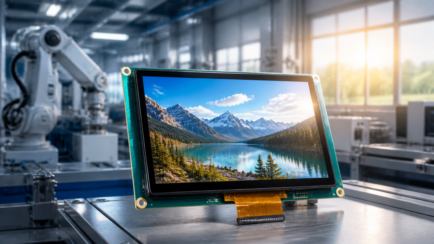
Most projects converge on an industrial display module built around a wide-temperature cell, an IPS TFT module where colour consistency across the cone is the requirement, or a TFT display where cost dominates and the viewing cone is narrow.
Sunlight readability, viewing cone and touch are decided by the module stack, so the supplier review is really a stack review. Fix the worst-case illuminance and temperature first, demand measured data at those conditions, and let the price comparison come last.
References
- ISO 9241-307:2008 — Ergonomics of human-system interaction — Part 307: Analysis and compliance test methods for electronic visual displays. International Organization for Standardization. https://www.iso.org/standard/40102.html
Read more
Wearable AMOLED customization hinges on three engineering challenges that cannot be glossed over—fitting the display to a curved wrist surface, designing.
Sony launched the ECX350F micro OLED display microdisplay module, compressing pixel pitch to 5.1 micrometers while delivering an unprecedented peak.
Leave a comment
This site is protected by hCaptcha and the hCaptcha Privacy Policy and Terms of Service apply.