



Micro OLED Module for Industrial Use | Ruggedness, Visibility, Applications
Industrial micro OLED selection turns on three questions: does the package survive the environment it will live in, is it bright enough against the ambient light actually present, and does its lifetime at that brightness match the service interval. Everything else — resolution, colour, interface — is settled after those three, because a module that fails any of them fails in the field.
Why the backplane helps
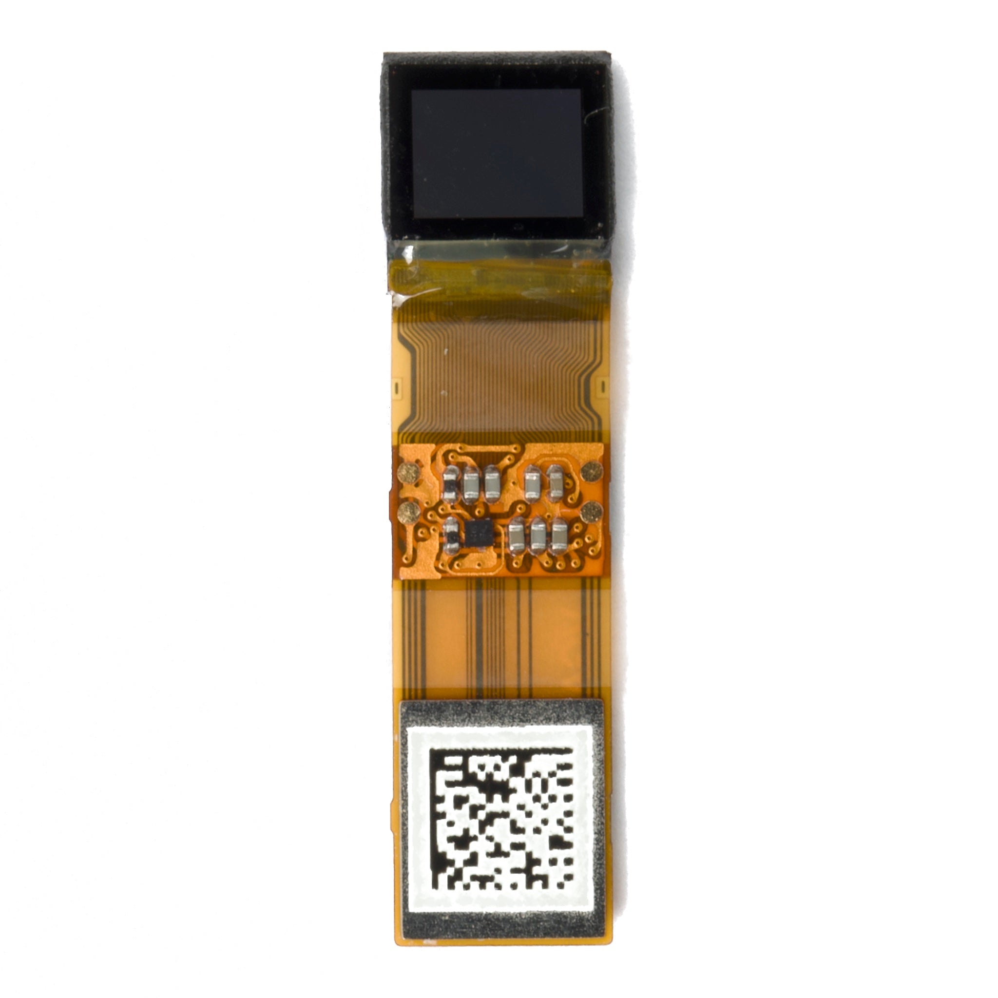
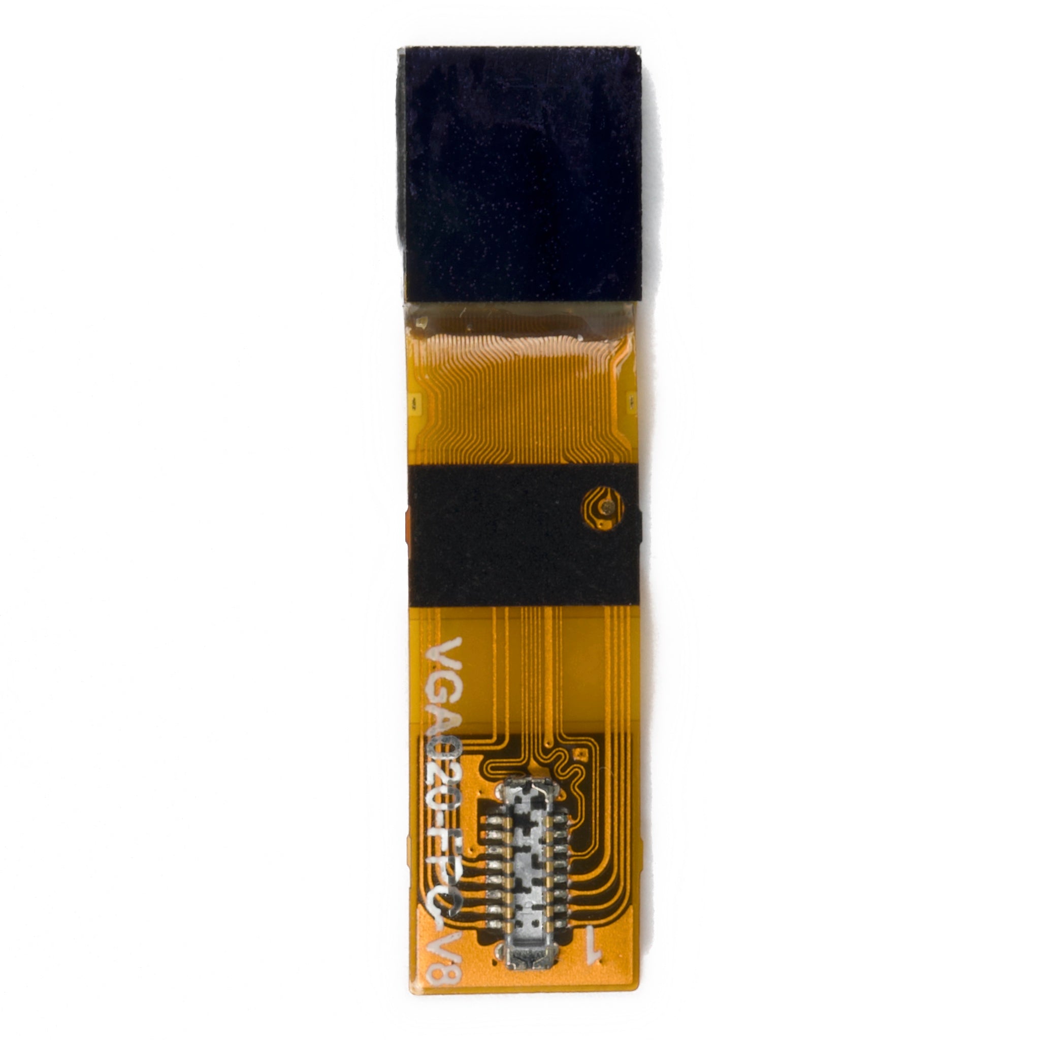
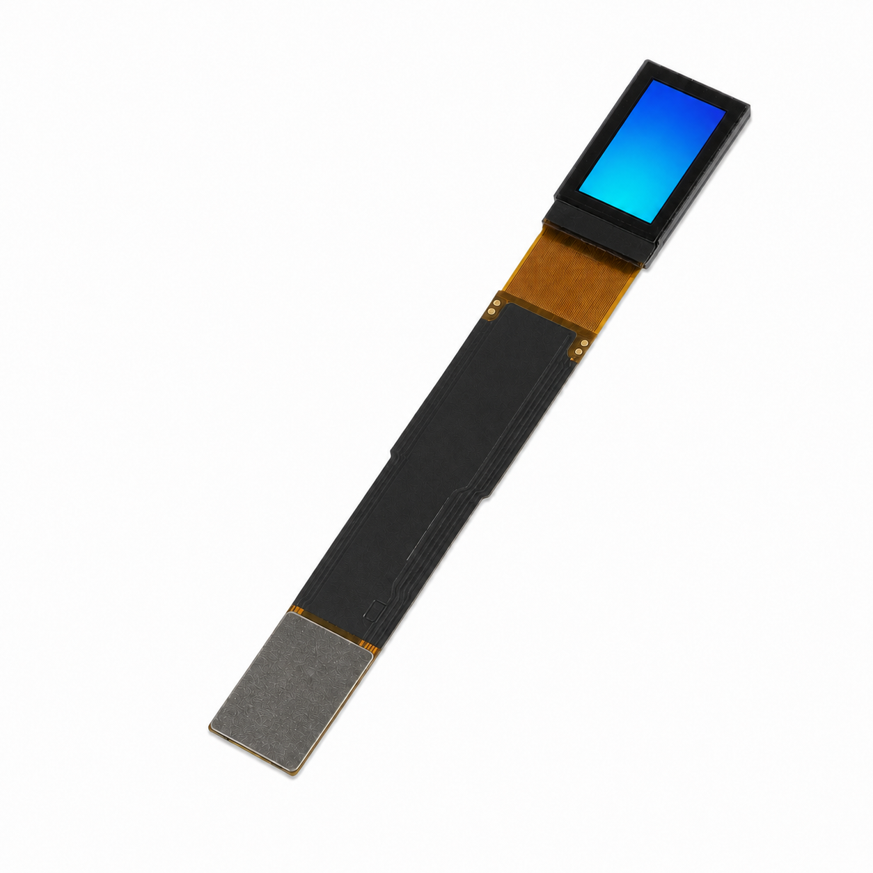
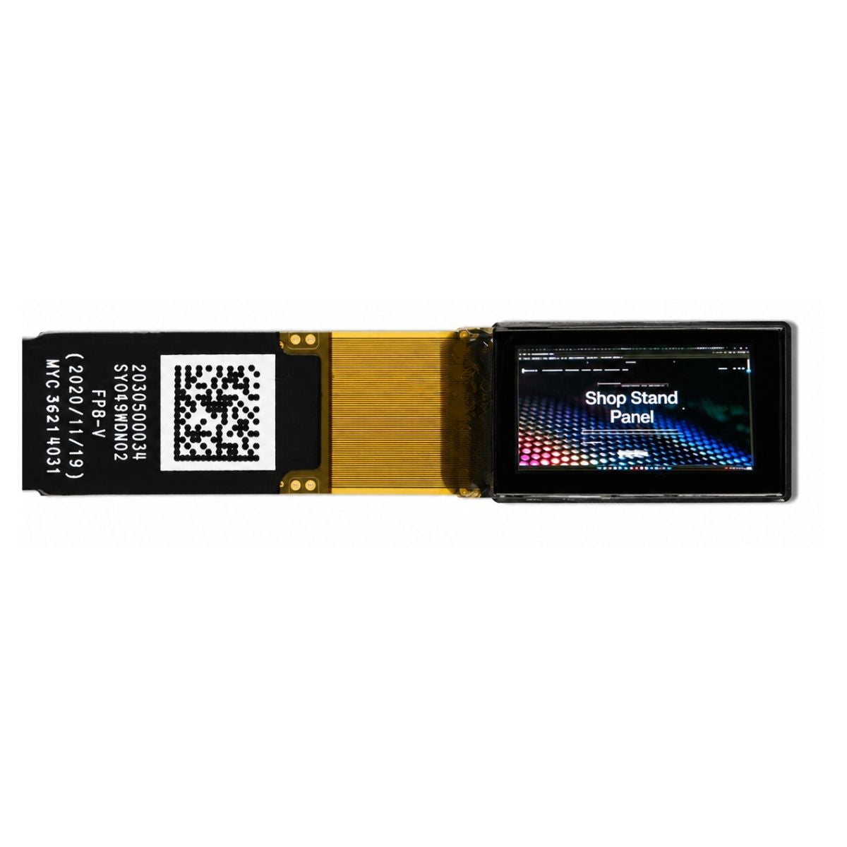
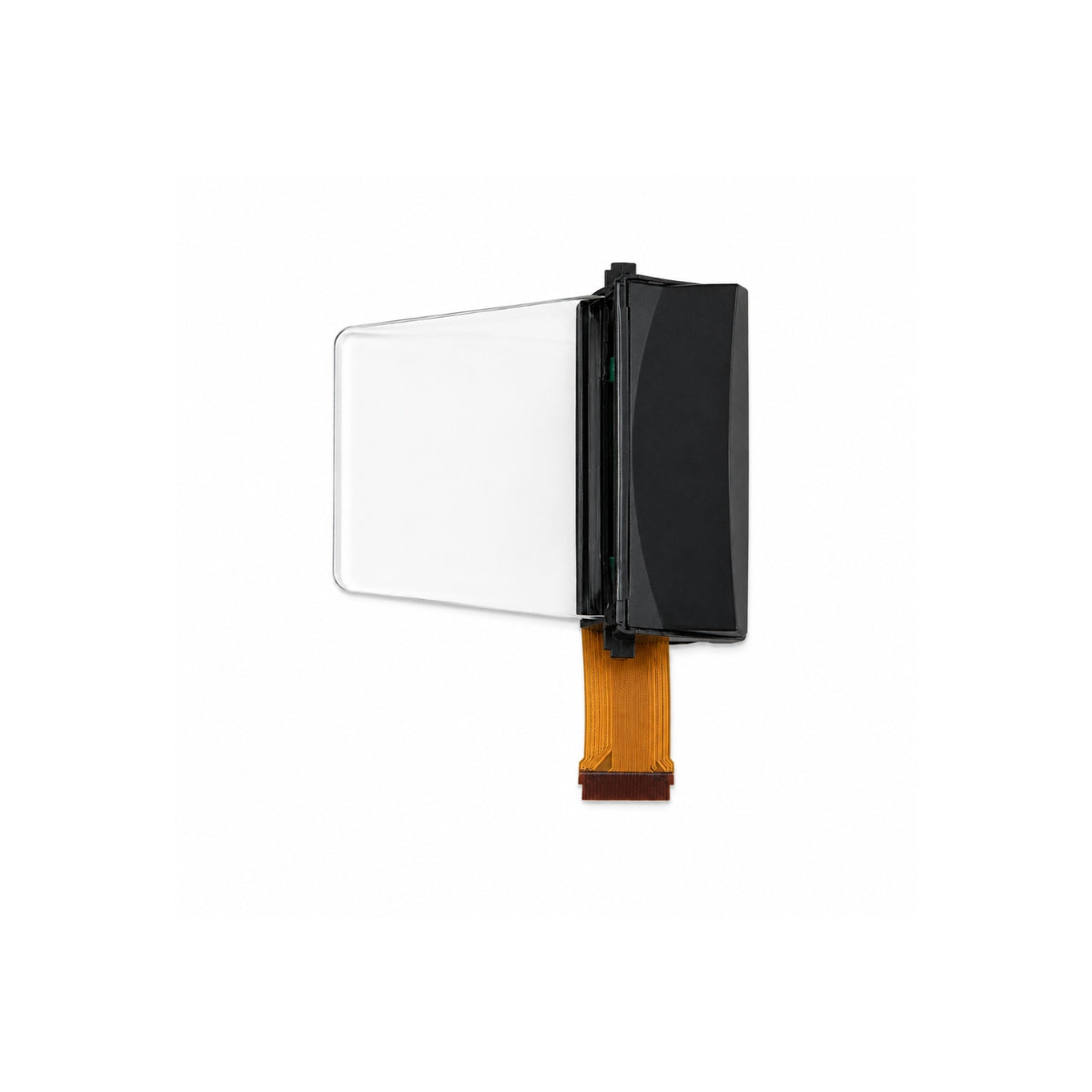
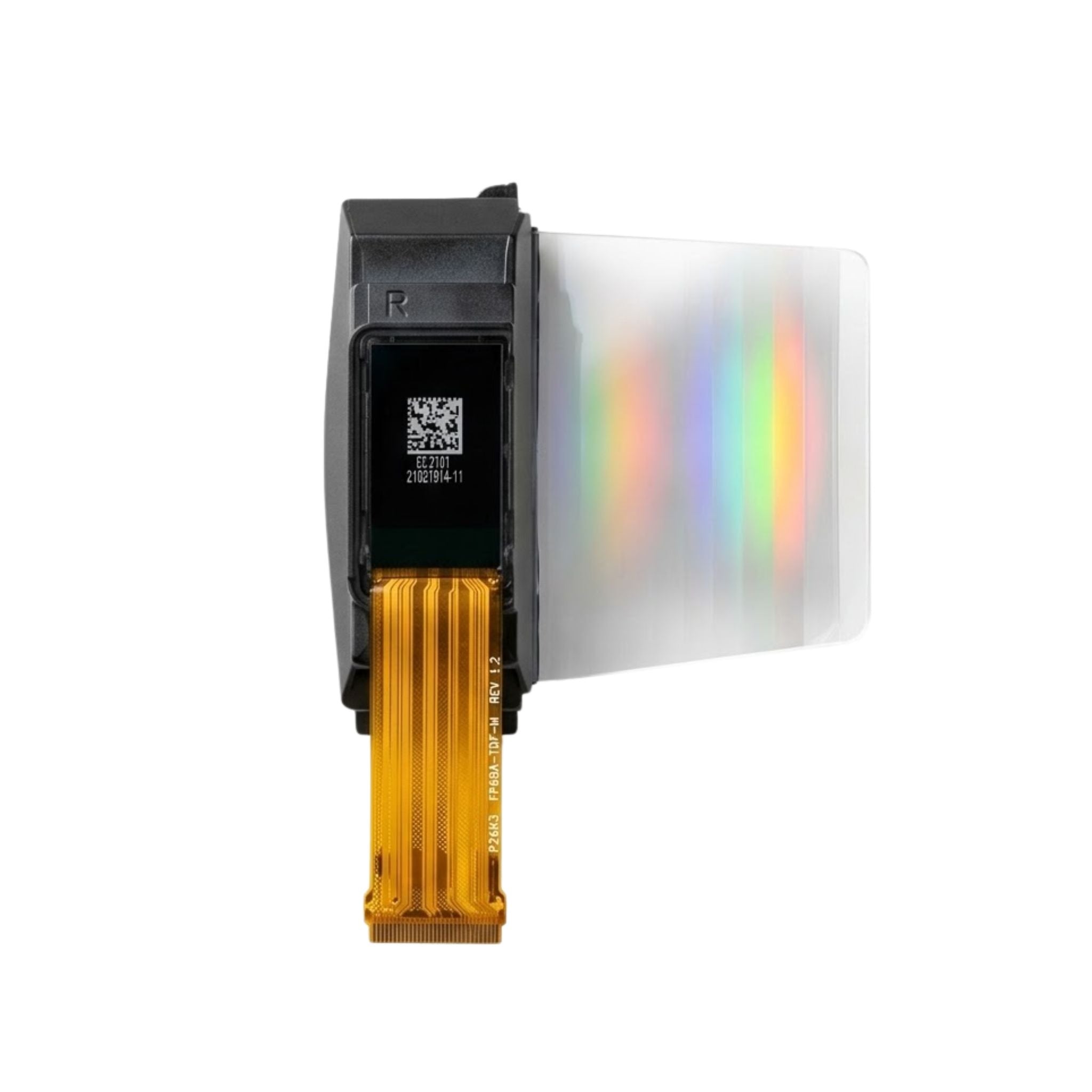
A micro OLED is built on a silicon chip rather than on a glass sheet. The active area is a single die a few millimetres to a couple of centimetres across, which changes the mechanical picture completely: there is no large, thin glass plate to flex, no sealed cell of liquid crystal to rupture, and no backlight stack to separate under vibration.
That does not make the package indestructible. The die still sits behind a cover, the flex tail is still a fatigue point, and the organic layers still need protection from moisture. The advantage is that the fragile element is small and can be potted, bonded and mounted as a solid unit rather than supported at its edges.
Environmental ratings and what they mean
Ask for the test standard, not the adjective. Temperature range should name the operating and storage limits separately, because a module that survives storage at one extreme may not operate there. Vibration is normally quoted against IEC 60068-2-6 with a frequency band, an acceleration or displacement, and a duration per axis; without all three the number is not comparable.
Shock is quoted against IEC 60068-2-27 as a pulse shape, peak acceleration and duration. A half-sine pulse of a given height means something quite different from a trapezoidal one, so read the waveform as well as the amplitude.
Ingress protection follows IEC 60529. An IP rating describes dust and water resistance of the enclosure as tested, not of the bare module, so a display inside a sealed housing inherits the housing's rating. Confirm whether the figure applies to the module alone or to the assembled unit, because the answer decides who is responsible for the seal.
Sealing and optical bonding
Moisture is the main long-term threat to an organic stack. Thin-film encapsulation on the die, a desiccant where used, and a sealed module outline all serve the same purpose, and the supplier should be able to say which applies. Condensation is the practical case: a cold module brought into a warm humid space will collect water on its outer surface, and that is why the front cover and the bond line matter as much as the encapsulation.
Optical bonding fills the gap between the panel and the cover glass with an index-matched resin. It removes two reflecting interfaces, which raises contrast in bright light and improves mechanical robustness by removing a void that can flex. For an industrial instrument used near windows or outdoors, bonding is usually worth more than an extra step of panel brightness.

Visibility in bright ambient light
Reflected ambient light adds to both the white and the black state, so the contrast you see falls as the environment brightens. The panel's own black level barely changes; what changes is the light bouncing off the cover glass, the polariser and any air gap. This is why an emissive display that looks superb in a control room can wash out on a loading dock.
Three levers move the result: lower reflectance through coating and bonding, higher panel luminance, and a UI that does not depend on subtle tonal differences. In high ambient light, saturated colours and thick strokes survive better than fine grey gradients, and that is a design decision as much as a component one.
Compare candidates by measurement rather than by datasheet. Place the module in the intended enclosure, put it under the light level of the actual workplace, and photograph it next to a reference. Luminance and contrast figures are only meaningful with stated conditions, which is what standardised display measurement exists to provide.[1]
Thermal management at high brightness
Emitting more light costs more current, and that current becomes heat in a very small package. In a sealed metal housing the heat has nowhere to go, so a module run at its maximum luminance for hours will settle at a higher temperature than the same module on a bench. OLED efficiency and colour both shift with temperature, and accelerated aging follows.
Design the thermal path deliberately: a thermally conductive potting compound or gap filler to the housing, a mounting surface with real contact area rather than four standoffs, and ventilation or a heatsink where the enclosure allows it. Then measure the panel temperature at the worst-case ambient, not the board temperature.
Lifetime at duty cycle
Lifetime figures are meaningless without the drive condition. A module quoted for a long life at half brightness may reach a small fraction of that at full brightness, because aging accelerates with current density. Ask for the luminance, the drive mode and the end-of-life criterion behind any hour count.
Then apply your own duty cycle. An instrument that displays a static screen for eight hours a day accumulates far more stress on the same pixels than one that cycles content, and the static case is where differential aging and image retention appear first. Blanking, dimming and periodic pixel shifts are cheap countermeasures that belong in the firmware specification from the start.
Applications
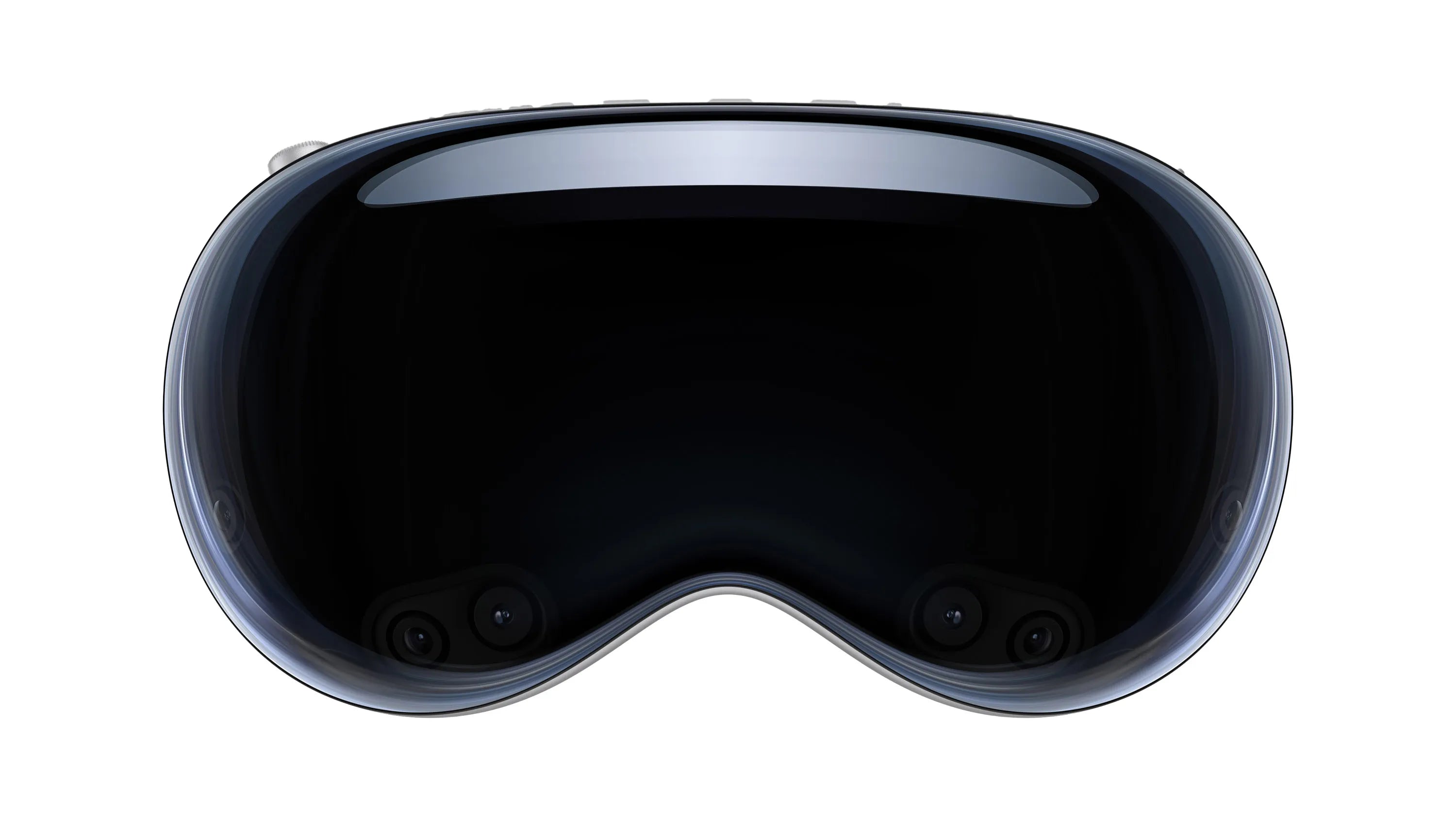
Head-mounted industrial tools use micro OLED for its size and its ability to show a bright image in a package that fits a temple arm. The constraint is usually the optical train and the battery, not the panel.
Surgical and diagnostic consoles use it for grayscale fidelity and contrast in a dim room, where the requirement is a stable, monotonic ramp rather than raw luminance. Regulatory clearance applies to the assembled system, and the display specification is one input to that work.
Avionics and vehicle displays use it where wide temperature range and sunlight readability matter, though the qualification burden for flight hardware is far beyond a general industrial module and should be treated as a separate programme.
Panel PCs, portable test gear and machine HMIs use it where a small, bright, wide-temperature display replaces a larger LCD behind a heater. In those designs the win is usually depth and cold-start behaviour rather than resolution.
Qualification checklist
- Operating and storage temperature stated separately, with test duration.
- Vibration and shock quoted with standard, band, level and axis count.
- IP rating attributed to module or enclosure, with the test standard named.
- Encapsulation method and a moisture resistance statement.
- Whether the front cover is bonded, and with what.
- Luminance at the operating temperature, sustained rather than peak.
- Lifetime definition at the luminance you intend to run.
- Thermal path specified: potting, gap filler, mounting contact area.
Ruggedised modules and matching mechanical parts are listed in our micro OLED collection and the wider industrial display range. Where the enclosure has room and the brightness requirement is moderate, a TFT module with a wide-temperature specification often costs less for the same service life.
Qualify the package, not the panel. Temperature, sealing, bonding and the thermal path decide whether the instrument survives its first winter, and each of them can be checked before the first production order.
References
- ISO 9241-307:2008 — Ergonomics of human-system interaction — Part 307: Analysis and compliance test methods for electronic visual displays. International Organization for Standardization. https://www.iso.org/standard/40102.html
Read more

Micro OLED panels vary: qVGA (320x240) for low-power, WVGA (800x480) for clarity; RGB variants hit 1M:1 contrast (mono: 500k:1), <5mW at 30Hz. Variants.
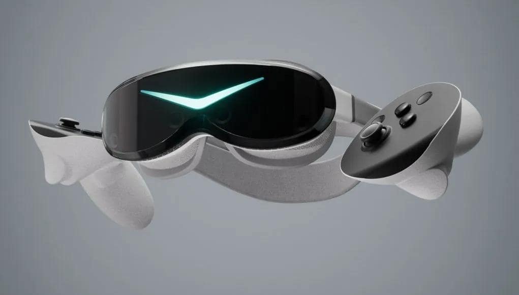
Choose Micro OLEDs for VR: 0.9" panels deliver 50°+ FOV, sub-10μs gray-scale response (system latency <20ms to reduce dizziness), and >1M:1 contrast.
Leave a comment
This site is protected by hCaptcha and the hCaptcha Privacy Policy and Terms of Service apply.