









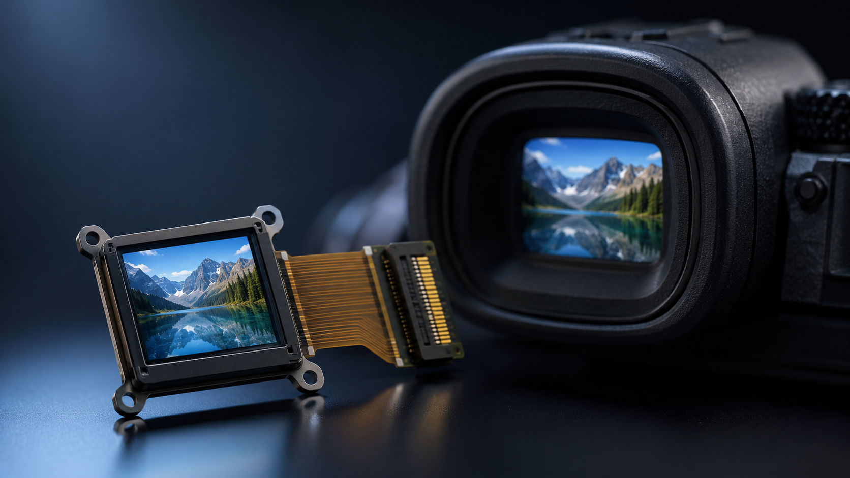
Micro OLED Module Supplier for EVF | High PPI, Fast Response, Compact Design
EVF viewfinders demand a display that can combine high pixel density, fast response, low latency, and a compact optical form factor. Among currently commercialized near-eye display technologies, Micro OLED modules are one of the most mature and widely adopted solutions for high-end EVF applications. Displaymodule focuses on compact display module integration and supports custom display solutions for camera, XR, industrial, and near-eye display projects.

Know the Module
What It Is
A Micro OLED module uses a single-crystal silicon wafer as the driver backplane, with organic light-emitting diode layers deposited onto the pixel circuitry to form an active-matrix organic electroluminescent microdisplay. Unlike conventional LCD-based solutions, Micro OLED does not require a backlight. Its self-emissive structure enables wide viewing angles, high contrast, fast pixel response, and a compact optical engine, making it suitable for near-eye applications such as EVFs, AR/VR devices, and industrial viewfinders.
The manufacturing challenge for Micro OLED lies in silicon backplane design, OLED deposition uniformity, pixel defect control, and package barrier performance. OLED materials are sensitive to moisture and oxygen, so display-grade encapsulation must provide strong water vapor and oxygen barrier protection. In industry discussions, OLED encapsulation requirements are commonly expressed using water vapor transmission rate (WVTR) in g·m⁻²·day⁻¹ and oxygen transmission rate (OTR) in cm³·m⁻²·day⁻¹. For high-reliability OLED devices, WVTR targets around 10⁻⁶ g·m⁻²·day⁻¹ are often referenced, depending on device structure, lifetime target, and test conditions.
From a display performance perspective, EVF specifications have evolved from early low-resolution LCD or LCoS solutions to high-resolution OLED and Micro OLED displays. A typical high-end EVF may use a 0.5-inch to 0.7-inch class microdisplay with several million dots, high refresh rate, and high magnification optics. For example, a 1920×1080 panel at 0.6-inch diagonal corresponds to approximately 3670 PPI, while the same resolution at about 0.83-inch diagonal corresponds to approximately 2645 PPI. Therefore, suppliers must define resolution, diagonal size, and pixel pitch consistently when specifying Micro OLED modules.
- Typical EVF display range: 0.5-inch to 1-inch class diagonal, from HD to QHD-class resolution depending on product tier
- Pixel density: commonly above 2000 PPI for high-end near-eye Micro OLED applications
- Response speed: typically in the microsecond to sub-millisecond range, depending on measurement method and drive condition
- Operating temperature: often specified by module design and customer requirement; industrial-grade targets may extend toward -40°C to +85°C
The core competitive advantage of a module manufacturer is not only the ability to provide samples, but also the ability to maintain optical consistency, electrical stability, defect control, supply continuity, and long-term technical support during production.
EVF (Electronic Viewfinder) is a technology that replaces or supplements optical viewfinding with a miniature electronic display, enabling photographers to preview exposure, white balance, focus, framing, and shooting parameters before capturing an image. It is widely used in mirrorless cameras, cinema cameras, and near-eye imaging systems.
For procurement teams, it is important to distinguish between nominal datasheet specifications and verified production performance. Resolution, brightness, contrast, color uniformity, pixel defects, display latency, interface compatibility, and optical alignment should be validated through sample testing and batch inspection rather than relying only on typical values.
Where It Fits
EVF display requirements are more demanding than ordinary consumer display requirements because the screen is viewed through magnifying optics and placed very close to the eye. Key requirements include high pixel density to reduce visible pixel structure, fast response to reduce motion smear, high contrast for low-light scenes, stable brightness, low power consumption, and low display latency for real-time framing.
Micro OLED uses a CMOS silicon backplane, allowing small pixel pitch and compact display size. This makes it well suited for near-eye optical systems where high resolution must be achieved within a small physical area. Compared with LCD-based EVF solutions, Micro OLED generally provides better black level, higher contrast, faster pixel response, and a thinner optical engine because it does not require a backlight.
From a market segmentation perspective, entry-level cameras may still use lower-cost LCD or OLED EVF solutions, while high-end mirrorless and cinema cameras increasingly adopt high-resolution OLED or Micro OLED EVFs. Flagship camera models such as Sony Alpha 9 III and Canon EOS R3 use high-resolution OLED EVFs with high refresh-rate viewfinding modes, reflecting the importance of fast, low-latency display performance in sports, wildlife, and action photography.
- Entry-level EVF: cost-focused LCD or lower-resolution OLED solutions, depending on camera positioning
- Mid-range EVF: higher-resolution OLED or compact near-eye display solutions with improved refresh rate and contrast
- Flagship/high-speed EVF: high-resolution OLED or Micro OLED-class solutions with high refresh rate, low latency, and strong optical integration
For module purchasers, the practical takeaway is that high-end EVF design usually requires a display technology that can combine compact size, high pixel density, fast response, and high contrast. Micro OLED is one of the strongest commercially mature options for this requirement set.
Sony Alpha 9 III is a full-frame mirrorless camera with a global-shutter image sensor, and its high-resolution OLED EVF supports high refresh-rate viewing modes. Such products illustrate why display response, refresh rate, and latency have become key factors in flagship sports and action photography systems.
When comparing EVF technologies, procurement teams should avoid evaluating only static resolution. Dynamic image clarity, perceived latency, black level, brightness stability, color consistency, and optical compatibility are equally important for real-world viewfinder performance.
Key Parts
A complete EVF Micro OLED module typically consists of five core functional blocks: CMOS driver backplane, OLED emissive stack, encapsulation barrier, optical lens assembly, and flexible printed circuit or board-level interface. Each block directly affects final module performance, reliability, and integration difficulty.
The CMOS driver backplane integrates pixel drive circuits, row and column drivers, timing control, and sometimes additional display compensation functions on a silicon substrate. Mature semiconductor process nodes are commonly used because Micro OLED requires high uniformity, low defect density, and stable analog drive behavior rather than the most advanced logic process. Pixel pitch, aperture ratio, drive current uniformity, and defect control all influence final image quality and yield.
The OLED emissive layer may use different technology routes, including white OLED with color filter, RGB OLED deposition, or other proprietary stack designs depending on supplier capability, brightness target, color gamut requirement, and cost target. RGB deposition can provide strong color performance but is more difficult to manufacture at very small pixel pitch. White OLED with color filter can simplify some manufacturing steps but may involve trade-offs in efficiency and color performance.
The encapsulation barrier layer is essential because OLED materials degrade when exposed to moisture and oxygen. Glass sealing, thin-film encapsulation, hybrid encapsulation, and other barrier structures may be used depending on module size, lifetime requirement, and product environment. Barrier performance should be specified with correct units and test methods, such as WVTR in g·m⁻²·day⁻¹ and OTR in cm³·m⁻²·day⁻¹.
| Functional Layer | Technical Solution | Key Parameters |
|---|---|---|
| CMOS Driver Backplane | Silicon-based active-matrix backplane | Pixel pitch, uniformity, defect density, drive stability |
| OLED Emissive Layer | White OLED + color filter or RGB OLED stack | Brightness, color gamut, lifetime, efficiency |
| Encapsulation Barrier | Glass sealing, thin-film, or hybrid encapsulation | WVTR, OTR, lifetime, environmental reliability |
| Optical Lens Assembly | Aspherical lens or custom eyepiece optics | Distortion, eye relief, magnification, diopter range |
| FPC Interface | MIPI DSI, LVDS, RGB, or custom interface | Signal integrity, connector type, pin pitch, EMI control |
Understanding these five functional blocks is the foundation for evaluating supplier capability. A reliable supplier should be able to explain trade-offs among brightness, lifetime, power consumption, resolution, optical design, and mechanical constraints rather than simply quoting a headline PPI value.
A professional Micro OLED module specification should define resolution, active area, diagonal size, pixel pitch, brightness, contrast, color gamut, refresh rate, interface, power consumption, operating temperature, storage temperature, pixel defect criteria, and reliability test conditions.
For engineering evaluation, buyers should request full electrical and optical documentation, including interface timing, recommended power sequencing, connector definition, optical center tolerance, mechanical drawings, thermal guidance, and acceptance criteria for pixel defects and luminance uniformity.
Check the Quality
Clear Image
The core value of an EVF is to help the user judge focus, exposure, framing, and scene detail before capture. For this purpose, display clarity is determined not only by nominal resolution or PPI, but also by optical magnification, fill factor, brightness, contrast, pixel structure visibility, color uniformity, and lens quality.
In practical evaluation, "clear image" should not be judged solely by the PPI figure on the datasheet. The effective aperture ratio or fill factor is also important because it affects brightness, perceived pixel structure, optical efficiency, and power consumption. In near-eye systems, lens design and display-panel matching can be just as important as the display panel itself.
Brightness should be evaluated under realistic optical conditions. A panel-level luminance value does not directly equal the brightness perceived at the eye after passing through the EVF optical system. Optical transmission loss, eyepiece design, diopter adjustment, and exit pupil geometry all affect final viewing performance. Therefore, procurement teams should request both panel-level and module-level optical test data.
- PPI example: 1920×1080 @ 0.6-inch diagonal is approximately 3670 PPI
- PPI example: 2560×1440 @ 0.7-inch diagonal is approximately 4195 PPI
- Key optical metrics: luminance, contrast, color coordinates, uniformity, distortion, eye relief, and exit pupil
- Image quality checks: pixel defects, mura, color shift, grayscale linearity, and dynamic image clarity
Purchasers should require suppliers to provide measured reports for each production batch when appropriate, including luminance, uniformity, color coordinates, pixel defect inspection, and optical alignment data. Batch-to-batch consistency should be defined contractually in the product specification or quality agreement.
Reliability testing for Micro OLED modules should be defined through a clear test plan. Common references may include high-temperature operation, low-temperature operation, temperature cycling, high-temperature/high-humidity storage or bias testing, and accelerated stress tests. Brightness degradation limits should be specified by customer requirement rather than attributed broadly to a single JEDEC standard.
Dynamic clarity is also critical for EVFs. At a 120 Hz refresh rate, each frame lasts about 8.3 ms. A display with microsecond-level pixel response can settle quickly within the frame period, helping preserve perceived sharpness during panning or fast subject tracking. However, total EVF latency also depends on the image sensor readout, image processor, interface transmission, display driver, and optical system.
Fast Response
The response speed of an EVF display directly affects perceived motion clarity and viewfinder confidence. Excessive pixel response time can cause motion smear, while excessive system latency can make the viewfinder feel disconnected from the real scene. These issues are especially important in sports, wildlife, racing, and handheld video applications.
Micro OLED generally provides very fast pixel response because OLED emission can change rapidly with drive current. However, response time should be specified with a clear measurement method, such as gray-to-gray transition, black-to-white transition, temperature condition, brightness level, and drive waveform. Comparing response values across display technologies without identical test methods can be misleading.
For EVF applications, response time is only one part of the total display experience. Refresh rate, frame buffering, image processing delay, sensor readout speed, interface bandwidth, driver timing, and optical persistence all contribute to perceived latency. Therefore, a professional evaluation should test end-to-end latency from camera sensor input to visible image output, not only panel-level pixel response.
- Typical Micro OLED advantage: very fast pixel response and high contrast
- Important system metrics: refresh rate, end-to-end latency, frame buffering, and motion clarity
- Useful test methods: high-speed camera latency test, gray-to-gray measurement, flicker test, and dynamic MTF evaluation
- Dimming evaluation: PWM frequency, low-brightness flicker, DC dimming behavior, and visible artifacts
Fast response is not just a technical specification. For professional EVF users, the viewfinder must remain predictable and trustworthy during rapid motion. A supplier should therefore provide not only response-time claims, but also test data under relevant temperature, brightness, and refresh-rate conditions.
Canon EOS R3 uses a 5.76-million-dot OLED EVF with a high-refresh-rate viewing mode, and its eye-control autofocus system demonstrates how EVF quality, refresh rate, latency, and camera processing work together to create a responsive shooting experience.
When evaluating suppliers, procurement teams should request driver timing information, supported refresh rates, interface bandwidth requirements, recommended cable length, EMI guidance, and signal-integrity margins. For high-resolution EVF modules, MIPI DSI or LVDS signal quality can become a practical integration risk if cable routing and grounding are not designed carefully.
Stable Supply
Procuring EVF modules is different from purchasing ordinary electronic components. Camera and optical-device development cycles can be long, and once a display module is designed into the optical, mechanical, electrical, and firmware architecture, changing suppliers may require redesign, revalidation, and new certification work.
The core of supply stability is supply chain depth. Key upstream elements for Micro OLED modules may include silicon backplanes, OLED materials, encapsulation materials, display driver ICs, FPCs, connectors, optical components, and assembly capacity. Single-source dependency in any critical part can create risk, especially for long-lifecycle camera or industrial products.
A professional supplier should be able to discuss supply continuity, end-of-life management, material change notification, production capacity, lead time, quality control, and long-term support. For long-term projects, buyers should consider using a formal quality agreement, product change notification process, and last-time-buy mechanism.
- Supply chain review: identify critical materials, single-source parts, and geographic risk
- Lifecycle support: define production continuity, EOL notice period, and last-time-buy options
- Quality control: specify incoming inspection, optical testing, pixel defect criteria, and traceability
- Compliance: verify RoHS, REACH, conflict minerals, and customer-specific material requirements
When evaluating suppliers, purchasers should request a supply chain overview, production capability statement, quality management certificates, material compliance declarations, and product change notification policy. If a supplier can only provide verbal claims of stable supply without documentation, the long-term risk should be considered high.
The EU RoHS Directive 2011/65/EU and REACH regulation impose material compliance requirements on electronic display modules. Micro OLED modules intended for the European market should be assessed for restricted substances, SVHC declarations, and applicable exemptions. RoHS should not be confused with the EU Toy Safety Directive, which is a separate regulatory framework.
Material change control is especially important for OLED products because changes in organic materials, encapsulation process, adhesive, FPC, or driver settings can affect brightness, color, lifetime, and reliability. Buyers should require advance notification and requalification for any critical material or process change.
Choose a Supplier
Real Support
Procuring Micro OLED modules is not a simple "order by specification" transaction. From specification confirmation, optical-mechanical design integration, firmware tuning, interface debugging, thermal design, and final validation, buyers may encounter technical issues that require supplier engineering support.
The first dimension for evaluating technical support capability is response quality. A professional supplier should be able to provide timely engineering responses, clear documentation, and practical troubleshooting guidance. For camera and near-eye display projects, support may involve optical simulation, mechanical tolerance analysis, interface timing review, color calibration, brightness control, and failure analysis.
The second dimension is technical service depth. Buyers should check whether the supplier can provide optical-mechanical design references, interface configuration guidance, register settings, firmware support, test fixtures, reliability data, and on-site or remote debugging when needed. This depth of support is often the difference between a true engineering supplier and a simple trading company.
- Engineering support: optical, electrical, mechanical, firmware, and reliability guidance
- Documentation: datasheet, integration guide, mechanical drawings, interface timing, and test reports
- Debug support: signal integrity, power sequencing, color calibration, brightness tuning, and failure analysis
- Project support: sample review, design-in support, pilot production, and mass-production transfer
It is recommended that purchasers arrange a technical capability assessment before formal cooperation. The supplier can be asked to solve several realistic integration problems, such as MIPI signal instability, brightness non-uniformity, optical center deviation, low-temperature startup failure, or color calibration drift.
A capable Micro OLED module supplier should be able to explain not only what the module specification says, but also why each parameter matters in the final optical system and how it can be verified during engineering validation.
One practical test for evaluating supplier depth is to ask for a signal-integrity review of a high-resolution display interface through a realistic flexible cable length. A strong supplier should be able to provide layout guidance, impedance requirements, grounding recommendations, and test suggestions rather than simply referring the buyer to the chipset vendor.
Custom Options
The procurement value of an EVF module often lies not in buying a standard display, but in obtaining a solution that fits the customer’s optical path, mechanical envelope, power budget, interface architecture, and product positioning. Each camera or near-eye device has different requirements, so customization capability can directly affect final product competitiveness.
The first layer of customization is optical parameter matching, including display size, active area, resolution, aspect ratio, eyepiece design, magnification, eye relief, distortion control, and optical center tolerance. A supplier with strong optical integration capability can help reduce iteration cycles and improve final viewfinder performance.
The second layer is electrical and firmware customization, including signal interface type, timing configuration, brightness control, gamma setting, color calibration, standby mode, power sequencing, and thermal protection. For advanced near-eye systems, additional integration may include sensors, eye-tracking components, or application-specific control logic.
The third layer is mechanical customization, including module outline, FPC shape, connector position, mounting holes, tolerance stack-up, thermal path, shielding, and assembly process. In compact camera bodies, even small changes in module thickness or connector location can significantly affect system design.
- Size range: selected according to optical design, resolution target, and mechanical envelope
- Resolution options: from entry-level EVF requirements to high-resolution near-eye display applications
- Interface types: MIPI DSI, LVDS, RGB parallel, or customer-specific interface depending on system design
- Firmware customization: brightness control, gamma, standby mode, color calibration, and display compensation
- Mechanical customization: FPC, connector, bracket, thermal path, and module outline
Purchasers should involve potential suppliers during the specification definition stage. A qualified supplier should be able to identify trade-offs among resolution, brightness, power consumption, heat, lifetime, optics, cost, and manufacturability before the design is locked.
For custom Micro OLED module projects, the most valuable supplier input often comes before sampling: feasibility analysis, optical-electrical trade-off review, risk identification, and early cost-down suggestions.
For buyers evaluating customization depth, it is useful to request a design review that compares the proposed custom module with at least two alternative architectures. This helps determine whether the supplier is providing genuine optical-electrical co-design or only minor mechanical changes to a standard product.
Long-Term Fit
Camera and optical-device product lifecycles often extend for several years, and the same EVF module platform may be used across multiple models or product revisions. This means the supplier must support not only initial delivery, but also long-term lifecycle management, documentation stability, change control, and technical continuity.
The first critical indicator is roadmap alignment. A supplier should be able to discuss future display availability, next-generation resolution options, brightness and lifetime improvements, interface roadmap, and package changes. This helps buyers plan platform upgrades and avoid premature obsolescence.
The second is service continuity. For long-term projects, account engineers, application engineers, and quality contacts should be clearly assigned. If key personnel change, a structured handover process should protect project knowledge and avoid repeated debugging.
The third is operational soundness. Buyers should consider production capacity, quality system maturity, financial stability, material sourcing, and historical delivery performance. For long-lifecycle products, the lowest quotation is not always the lowest-risk choice.
- Roadmap alignment: review future display options, interface plans, and lifecycle status
- Service continuity: define account ownership, technical contacts, and escalation path
- Change control: require PCN, requalification, and documented approval for critical changes
- Operational health: evaluate capacity, delivery history, quality system, and long-term support capability
It is recommended that purchasers add a strategic fit assessment to supplier evaluation. In addition to current technical capability and pricing, buyers should evaluate the supplier’s understanding of camera and near-eye display trends, willingness to support long-lifecycle products, and readiness to cooperate on intellectual property, customization, and quality responsibilities.
The EVF and near-eye display markets are expected to continue evolving as cameras, XR devices, industrial viewers, and hybrid optical-electronic systems demand higher resolution, faster refresh rates, lower power consumption, and more compact optical engines.
EVF has become an essential viewfinding solution for modern mirrorless cameras and professional imaging equipment. Micro OLED occupies a strong position in high-end near-eye display applications because it combines high pixel density, fast response, high contrast, and compact form factor. For camera and device brands, choosing a module supplier with proven engineering support, customization capability, quality control, and stable supply is a key step in building a reliable and competitive product platform.
Read more
The rapid development of smart glasses, AR headsets, MR devices, and other near-eye optical products is reshaping the microdisplay market. OLEDOS, also known as OLED on Silicon or Micro OLED, has b...
Micro OLED displays, also known as OLED-on-Silicon displays, combine high pixel density, fast response, high contrast, compact size, and efficient power performance under suitable drive condition...
Leave a comment
This site is protected by hCaptcha and the hCaptcha Privacy Policy and Terms of Service apply.