









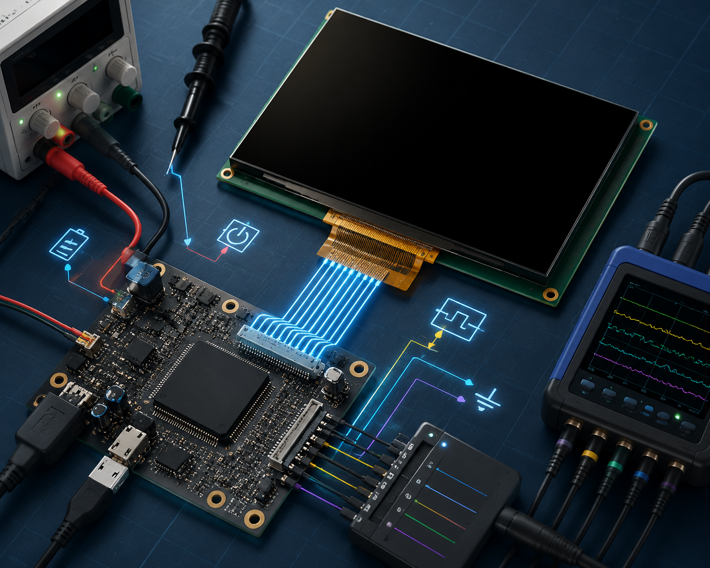
A MIPI DSI black screen usually comes from one of four places:
- Light output: an LCD backlight is off, or an OLED panel is not emitting light.
- Panel state: the panel has no power, is held in reset, remains asleep, or is still in Display Off mode.
- DSI link: commands or video packets do not reach the panel correctly.
- Pixel source: the host sends black pixels, transparent pixels, the wrong format, or data from the wrong memory address.
Check the display in that order. A missing power rail cannot be fixed with a gamma command. A lane-routing fault cannot be fixed with a longer reset delay.
MIPI DSI-2 defines the link between a host processor and a display and can run over D-PHY, C-PHY, or A-PHY.[1] The electrical checks in this article apply to conventional forwarded-clock D-PHY links. These links use a dedicated clock lane and one or more data lanes.[2] C-PHY, A-PHY, and embedded-clock D-PHY need different physical-layer tests.
For a simple introduction to the interface, read What Is MIPI DSI?

Get the Exact Panel Information
Before changing code, collect the documents for the exact panel model and revision:
- Full manufacturer and part number
- Hardware revision
- Display driver IC
- Connector pin assignment
- Power-on and power-off sequences
- Reset polarity and timing
- Number of DSI data lanes
- Supported lane-rate range
- Video mode or command mode
- Pixel format
- Native resolution and porch timing
- Official initialization command table
- Backlight or OLED power requirements
- Host-controller or bridge-chip documentation
Do not choose a driver only because another panel has the same resolution or controller IC. Two panels can use the same controller but require different power settings, gate timing, gamma data, scan direction, and initialization commands.
A useful initialization table must show more than hexadecimal bytes. It should also state the packet type, payload length, virtual channel, LP or HS mode, delay, read length, and whether an acknowledgement is expected. Linux stores the channel, packet type, flags, transmit length, and receive length as separate fields in a DSI message, so correct payload bytes alone do not prove that the transfer is correct.[3]
How to Read a TFT LCD Module Datasheet explains where to find the pin table, timing limits, reset sequence, and initialization data.
Read the Screen Symptom
The Screen Is Completely Dark
For an LCD, check the LED supply, LED current, backlight enable, PWM signal, connector, and flex-cable direction. Shine a flashlight across the screen at an angle. A faint image means the LCD may be receiving pixels while the backlight is off.
This flashlight test does not apply to OLED and AMOLED panels because their pixels make their own light. A MIPI Micro OLED module, for example, uses separate logic and OLED power rails rather than an LED backlight.
The Backlight Is On but the Image Is Black
A lit backlight proves only that the LED circuit works. The panel may still be held in reset, asleep, in Display Off mode, missing its vendor setup, receiving no DSI data, or displaying a black framebuffer.
Force the host to output full white, red, green, and blue. If every test stays black, check panel state, DSI traffic, and the pixel source. For OLED, also check the OLED power rails, internal brightness, and emission control.
The Screen Is White
A white LCD often has working glass power and backlight but no valid source-driver data. Possible causes include incomplete initialization, missing bias settings, wrong reset timing, or no video stream. White is only a clue: an uninitialized panel can also look black, gray, or noisy.
The Screen Flashes or Shows Lines
A brief flash followed by black can come from a voltage drop, current limiting, backlight protection, a D-PHY clock failure, or a driver that disables the panel after an error.
Random lines, flicker, or a partial image usually mean that some data is reaching the panel. Check lane order, pair polarity, lane rate, pixel packing, line timing, packet size, and signal quality.
Confirm the Panel Mode
A panel can use video mode, command mode, or support both. DSI and DCS provide control and image-transfer methods for these display designs.[4]
Video Mode
A video-mode panel expects the host to keep sending frames. This does not mean every lane must toggle without a break. Burst mode and non-continuous clock mode can contain normal idle periods.
The host must provide the correct line timing, frame timing, pixel packets, and repeated video stream. If the host stops sending the required frames, the image may disappear, freeze, or become unstable.
Command Mode
A command-mode panel may store pixels in internal memory. It can require a column address, page address, Memory Write command, pixel payload, tearing-effect synchronization, and an update trigger.
Some host controllers create these commands automatically. Others require software to send them. Check both the panel manual and host-controller manual.
For projects that use an AMOLED panel and a MIPI host, How to Drive a Round AMOLED Display with MIPI covers host selection, FPC wiring, panel power, and image output.
Check the Light Output
LCD Backlight
The LCD backlight is normally separate from the LCD timing controller and DSI receiver. Measure these signals at the panel connector, not only at the regulator:
| Signal | What to check |
|---|---|
| LED supply | Correct voltage while the LEDs are drawing current |
| Backlight enable | Correct voltage, polarity, and start time |
| PWM | Correct pin, period, polarity, and non-zero duty cycle |
| LED current | Inside the panel or LED-driver limit |
| Fault output | No open-string, overvoltage, or overcurrent fault |
PWM polarity, period, and duty cycle are separate settings. A non-zero software brightness value does not prove that the physical PWM waveform is correct.[5]
Do not use a universal test value such as “50% brightness.” Use a safe current and PWM setting from the panel or LED-driver document. Do not power a bare LED string from a fixed voltage without current control.
OLED Light Output
OLED and AMOLED panels do not use a separate backlight. Check logic power, positive and negative OLED rails, emission enable, brightness registers, and any panel-specific power IC. An OLED can receive valid DSI video and still remain black when its emission power is missing.
Check Every Power Rail
Measure all required external rails at the panel connector. Common names include VDD, VDDIO, IOVCC, VCI, AVDD, VSP, VSN, ELVDD, and ELVSS. Some datasheets also show VGH and VGL, but a finished module may generate them internally. Never apply an external voltage unless the pin is marked as a power input.
Linux panel descriptions often model power, reset or enable GPIOs, backlight, lane count, format, and mode flags as separate items. This reflects the fact that a panel can have correct DSI data while another required resource is still missing.[6]
| Rail | Required value | Allowed range | Measured value | Lowest startup value | Ripple |
|---|---|---|---|---|---|
| VDDIO | Panel specification | Panel specification | Connector measurement | Oscilloscope measurement | Peak-to-peak |
| VCI or VDD | Panel specification | Panel specification | Connector measurement | Oscilloscope measurement | Peak-to-peak |
| Positive bias | Panel specification | Panel specification | Connector measurement | Oscilloscope measurement | Peak-to-peak |
| Negative bias | Panel specification | Panel specification | Connector measurement | Oscilloscope measurement | Peak-to-peak |
Measure during power-up, reset, initialization, Sleep Out, Display On, video start, and light-output start. A rail can look correct when idle and drop when the panel turns on its analog circuits.
The Linux regulator API separates enable state, voltage, current limit, and operating mode. A regulator reported as enabled does not prove that the correct voltage reaches the panel under load.[7]
Look for Back-Powering
A panel can receive unwanted current through reset, TE, I2C, backlight enable, GPIO, or input-protection circuits while its main power is off. This can cause cold-boot failure, warm-reboot success, changing startup behavior, or current draw after shutdown.
Measure each control pin while the panel rails are off. Linux GPIO APIs also distinguish logical active and inactive states from the physical pin level, especially for active-low signals.[8]
Why Incorrect Startup Timing Causes a Black Screen gives more detail on the relationship between panel power, reset, commands, and OLED emission.
Check Reset and Start-Up Timing
Measure reset at the panel connector. Do not trust only a log message or the value passed to a GPIO function.
A common start-up flow is:
Enable the required rails
Wait until the rails are stable
Apply the required reset pulse
Release reset
Wait until the panel can accept commands
Send the vendor initialization
Send Sleep Out
Wait for the panel-specific delay
Start video and send Display On in the required order
Enable the backlight or OLED emission
This order is only a general example. Some panels require reset to be active before power rises. Others need a low pulse after power becomes stable. The position of video start and Display On also varies by panel and host.
| Time to measure | Best evidence |
|---|---|
| Power valid to reset release | Power and reset on the same oscilloscope capture |
| Reset pulse width | Oscilloscope |
| Reset release to first command | Oscilloscope plus timestamped driver log |
| Sleep Out to the next operation | Driver timestamp |
| Video start to visible light | DSI activity, backlight enable, or OLED emission signal |
Hardware Reset and Software Reset
Hardware reset uses the physical reset pin. DCS command 0x01 is Software Reset. The standard DCS opcodes are also defined in the Linux MIPI display header.[9]
Software Reset cannot fix missing power, wrong reset wiring, a panel held in hardware reset, bad bias rails, or lane-routing faults. Some panels also return vendor registers to default after Software Reset, so the full vendor table must be sent again.
Prove the First Command
For the first required command, log the command byte, packet type, packet length, virtual channel, LP or HS flag, and return value. Then check for command activity on data lane 0.
If the first command fails, stop the sequence. Sending another hundred commands only hides the first useful fault.
Check the Linux Display Path
Search the kernel log:
dmesg | grep -Ei "dsi|drm|panel|display|backlight|regulator|phy|clock"Look for panel probe, DSI attachment, deferred probe, missing regulators, missing GPIOs, unsupported formats, invalid lane counts, PHY timeouts, clock failures, transfer errors, and modeset failures.
Where supported, inspect DRM state:
cat /sys/class/drm/*/status
cat /sys/kernel/debug/dri/0/state
The debugfs path may require root access, mounted debugfs, DRM debug support, and a card number other than 0.
Check whether the connector is attached to an active CRTC, whether the primary plane is enabled, which framebuffer is attached, and which mode and pixel format are active. DRM treats connectors, CRTCs, planes, and framebuffers as separate parts of the display path.[10]
A CRTC is the timing engine that creates lines and frames. A plane is one image layer. A connector shown as connected does not prove that an embedded panel is displaying valid pixels.
Check the Driver Order
probe
→ attach
→ get modes
→ prepare
→ enable
→ disable
→ unprepare
The Linux DRM panel interface separates prepare, enable, disable, and unprepare so power, initialization, visible output, and shutdown can happen at the right stage.[11]
In many panel drivers, prepare handles power, reset, and commands, while enable makes the image visible or turns on the backlight. The exact split is panel-specific.
Remove Bootloader Dependence
A panel can work in the bootloader but fail in Linux because the bootloader left regulators, the D-PHY, panel registers, video timing, or the backlight already active.
Test Linux after a complete power removal. If possible, disable bootloader display setup and confirm that Linux can start the panel from a true off state.
Check Lane Wiring
Lane Count
A forwarded-clock D-PHY link has a clock lane and scalable data lanes.[2] Many embedded DSI hosts and bridges support up to four data lanes. Do not assume that only one, two, or four lanes are possible: some hardware supports three lanes, and the official Linux binding for the ADV7533/ADV7535 lists two-, three-, and four-lane input configurations.[12]
The configured count must match the host, bridge, PCB, connector, panel, device tree, and driver. A host configured for four lanes cannot send a valid four-lane stream through a board that routes only two.
A 7-inch 1200 × 1920 MIPI DSI module may specify four lanes, but that setting must not be copied to another panel without checking its datasheet.
Lane Order
Check the complete path:
Host logical lane
→ SoC package pin
→ PCB net
→ Connector pin
→ Panel lane
Some bridges support limited lane reordering, but this is a hardware feature, not a general DSI rule. The official Linux binding for the SN65DSI86, for example, describes specific lane-routing options and limits.[13]
Low-power command traffic normally uses data lane 0. A lane-0 fault can stop initialization and readback. A fault on another data lane may allow commands to work but break high-speed video.
Pair Polarity
Check the positive and negative wires of the clock pair and every data pair. Swapping the two wires in a pair is different from swapping lane numbers.
A reversed pair can break low-power state detection, high-speed data, or both. Some hosts and bridges can invert selected pairs in hardware; others need a PCB correction.
Check D-PHY Activity
D-PHY supports low-power and high-speed operation and can move between these states with low transition delay.[14]
Check for Activity
Use a suitable probe to answer these basic questions:
- Does command activity appear after reset?
- Does high-speed video start?
- Do all configured data lanes become active?
- Does traffic continue over complete frames?
- Does the link repeatedly start and stop?
A normal oscilloscope can show that a signal is active, but it cannot prove that packets, CRC, ECC, or eye quality are correct.
No Host Activity
If the host produces no clock or data activity, check the DSI host clock, PHY power, pin mux, runtime power management, driver attachment, packet generator, and display-controller enable.
Panel reset does not normally stop the host from creating a waveform. Reset becomes the main suspect when host activity exists but the panel does not respond.
Commands Appear but Video Does Not
If LP commands are visible but no high-speed video starts, check command return values, panel state, CRTC state, video-engine enable, bridge enable, and mode flags.
Clock Runs but Data Does Not
Observe at least one complete frame. In continuous-clock mode, the clock can run while data lanes are temporarily idle. If no data burst appears during a complete frame, check data-lane enable, the packet generator, DMA, FIFO, CRTC state, and video timing.
Traffic Starts and Stops
Read the first host error. Common causes include PLL unlock, FIFO underflow, LP timeout, HS timeout, CRC or ECC error, packet-size error, and a failed modeset.
Calculate the Lane Rate
Do not choose a lane rate from resolution alone. Start with the complete raster timing:
Horizontal total = active width + front porch + sync width + back porch
Vertical total   = active height + front porch + sync width + back porch
Pixel clock      = horizontal total × vertical total × refresh rate
Example:
Active resolution: 1280 × 800
Horizontal total: 1280 + 48 + 32 + 80 = 1440
Vertical total:   800 + 3 + 6 + 14 = 823
Refresh rate:     60 Hz
Pixel format:     RGB888
Data lanes:       4
The pixel clock is:
1440 × 823 × 60 = 71,107,200 Hz = 71.1072 MHzVisible Pixel Payload
1280 × 800 × 60 × 24 ÷ 4 = 368.64 Mbps per laneThis value includes only visible pixels. It does not include blanking or packet transport.
Pixel-Clock Estimate
71.1072 MHz × 24 ÷ 4 = 426.6432 Mbps per laneThis is a useful first estimate for an uncompressed RGB888 stream. Because the pixel clock was calculated from total timing, the result already includes the raster blanking ratio. Do not add the full blanking ratio a second time.
The final lane rate still depends on burst or non-burst mode, packet overhead, host design, PHY timing, the panel’s allowed range, and the frequencies the host PLL can actually generate. Use the host or bridge vendor’s calculation for the final register values.
For example, if the host can generate only 400, 450, or 500 Mbps per lane, 400 Mbps is below the estimate. 450 Mbps may work if the panel accepts it. 500 Mbps is not automatically better because it can exceed the panel limit or make a weak PCB link less stable.
Check Display Timing
Verify the values from the exact panel datasheet:
- Active width and height
- Horizontal front porch, sync width, and back porch
- Vertical front porch, sync width, and back porch
- Refresh rate
- Sync polarity when used
- Final rounded pixel clock
The active area contains visible pixels. The front porch is the wait after active pixels. The sync width marks the synchronization interval. The back porch is the wait before the next active area.
Wrong timing can cause a black screen, shifted image, rolling image, repeated lines, image wrap, flicker, or a partial picture.
Compare the panel datasheet, driver or device tree, final DRM mode, actual hardware clock, refresh rate, and DSI line-packet size. A clock framework may round the requested clock, so check the frequency that hardware actually uses.
Check Pixel Format
The format can change at four points:
- Framebuffer memory format
- Display-controller output format
- DSI packet format
- Panel input format
Common DSI formats include:
- RGB565: 16 transmitted bits per pixel
- RGB666 packed: 18 transmitted bits per pixel
- RGB666 loosely packed: 24 transmitted bits per pixel
- RGB888: 24 transmitted bits per pixel
An XRGB8888 framebuffer can be converted to RGB888 before DSI transmission. That is valid if the display controller is configured to perform the conversion.
DCS includes Set Pixel Format, and Linux defines its opcode as 0x3A.[4][9] Do not assume that changing the host format also changes the panel register.
| Symptom | First check |
|---|---|
| Red and blue are swapped | RGB/BGR order |
| Colors look posterized | RGB565, RGB666, or RGB888 mismatch |
| Pixels shift at regular intervals | Packing and payload length |
| White is correct but colors are wrong | Channel order and bit alignment |
Check DCS and Command Transport
MIPI DCS defines standard display-control functions and methods for sending image data to DSI displays.[4]
| Command | Hex | Purpose |
|---|---|---|
| Software Reset | 0x01 |
Reset the display controller |
| Read Display ID | 0x04 |
Read panel identification when supported |
| Read Error Count | 0x05 |
Read DSI error information when supported |
| Read Display Status | 0x09 |
Read display state |
| Read Power Mode | 0x0A |
Read power-related state |
| Enter Sleep | 0x10 |
Enter sleep mode |
| Exit Sleep | 0x11 |
Leave sleep mode |
| Display Off | 0x28 |
Disable visible output |
| Display On | 0x29 |
Enable visible output |
| Column Address | 0x2A |
Set the horizontal memory window |
| Page Address | 0x2B |
Set the vertical memory window |
| Memory Write | 0x2C |
Begin writing pixels |
| Address Mode | 0x36 |
Set scan direction and orientation |
| Pixel Format | 0x3A |
Set the panel interface format |
| Brightness | 0x51 |
Set brightness when the panel supports it |
These standard commands do not replace the vendor table. A panel may also need private power registers, gamma, VCOM, gate timing, source timing, scan direction, frame-rate settings, TE setup, or compression settings.
Use the Correct Packet Type
The same bytes can fail when sent as the wrong packet. Possible transfers include DCS short write, DCS long write, generic short write, generic long write, DCS read, and generic read.
B0 04
B6 3A D3
E0 00 0A 10 0D ...
The bytes above do not show whether the panel expects DCS or generic packets. Preserve the packet category, short or long format, payload length, LP or HS flag, virtual channel, delay, read length, and acknowledgement setting.
Keep Delays Beside Their Commands
Important waits can be required after power, reset, Software Reset, command-page switching, Sleep Out, Display On, and before power removal. Use the delay from the exact panel document. Do not copy a common value such as 120 ms without checking the panel.
If a longer delay fixes the screen, find out what was late: a regulator, reset release, bridge lock, host setup, or the panel’s internal analog start-up.
Check Every Return Value
Linux DSI write helpers return a negative error on failure and a transferred byte count on success.[3]
static int panel_send_dcs(struct panel_ctx *ctx,
                          const uint8_t *data,
                          size_t length)
{
    ssize_t ret;

    if (!ctx || !ctx->dsi || !data || length == 0)
        return -EINVAL;

    ret = mipi_dsi_dcs_write_buffer(ctx->dsi, data, length);
    if (ret < 0) {
        dev_err(ctx->dev,
                "DCS command 0x%02x failed: %zd\n",
                data[0], ret);
        return (int)ret;
    }

    if ((size_t)ret != length) {
        dev_err(ctx->dev,
                "DCS command 0x%02x short transfer: %zd/%zu\n",
                data[0], ret, length);
        return -EIO;
    }

    return 0;
}
A successful host return value proves that the host completed the transfer. It does not prove that the panel understood the command. Use readback or a visible state change when the panel supports it.
Check Readback
Useful reads can include Display ID, Display Status, Power Mode, Address Mode, Pixel Format, and Diagnostic Result. Readback needs panel support, bus turn-around, host receive support, the correct return-packet size, the correct virtual channel, and a valid timeout.
Check the returned byte count and whether the value changes after Sleep Out or Display On. Repeated 0x00 or 0xFF does not point to one cause; it can come from an unsupported read, wrong return size, a panel still in reset, or a host receive problem.
Test the Pixel Source
Use Simple Patterns
Test full white, red, green, blue, black, vertical bars, a checkerboard, and a one-pixel border.
| Result | Likely area |
|---|---|
| White works but colors are wrong | Pixel format or channel order |
| Image is shifted | Porch timing, packet size, or stride |
| Image wraps | Line length or command-mode memory window |
| Only part of the image appears | Resolution, payload length, or buffer size |
| Every pattern is black | Panel state, alpha, DMA, or wrong buffer |
Use a Built-In Test Generator
If available, use the panel self-test, bridge test pattern, or display-controller test pattern:
- If the panel self-test works, the panel glass and internal drivers are probably working.
- If a bridge pattern works, the bridge-to-panel path is probably working.
- If a display-controller pattern works, the DSI output path is probably working and the fault may be in framebuffer memory.
A known adapter can also provide a separate test source, but it must support the panel’s connector, power, lane count, timing, and initialization. A Type-C to MIPI DSI adapter is not automatically compatible with every MIPI panel.
Check the Framebuffer
Confirm that:
- The buffer contains non-zero pixels.
- The correct framebuffer is attached to the active plane.
- Plane and global alpha are not zero.
- The display controller can read the buffer address.
- The stride matches the width and pixel format.
- The cache has been synchronized when required.
- No overlay covers the test image.
Stride is the byte distance between the start of one image row and the next. On systems where the CPU and display controller do not share a coherent view of memory, the DMA API defines the required synchronization steps.[15]
Read the First Error
Host error names differ, but these groups are common:
| Error | Likely area | First action |
|---|---|---|
| ECC or CRC | Lane mapping, polarity, rate, or signal quality | Check lane wiring and test a supported lower rate |
| LP timeout | Reset, lane 0, packet type, or panel power | Check the first command |
| HS timeout | PHY timing, clock, or lane rate | Check the high-speed state change |
| FIFO underflow | Pixel input, memory speed, or timing | Test a lower supported mode and check DMA |
| PLL unlock | Reference clock, PHY power, or divider | Check clock and PHY setup |
| Packet-size error | Pixel format, active width, or payload size | Recalculate the line packet |
| Bus Turn-Around timeout | Readback path or unsupported read | Check receive settings and panel read support |
Clear old errors, perform one start-up, and record the first new error. Later errors may be side effects. For example, a failed PHY clock can create timeouts and FIFO errors afterward.
Check Power-Off
Do not use one shutdown order for every panel. A common flow is:
Disable the backlight or OLED emission
Send Display Off while commands are still available, if required
Stop or blank video at the point required by the host and panel
Send Enter Sleep while commands are still available, if required
Wait for the specified delay
Assert reset
Disable bias rails
Disable logic rails
The exact position of Display Off, video stop, and Enter Sleep depends on the panel and host.
Check that DSI signals do not back-power the panel, the rails turn off in the correct order, and the minimum off-time is met before restart. A bad shutdown can cause warm-reboot-only operation, excess standby current, residual images, or an unpredictable next start.
Quick Fault Map
| Symptom | First check |
|---|---|
| LCD is completely dark | Measure LED supply and current at the connector |
| Backlight is on but the image is black | Capture reset and the first LP command |
| DCS readback works but there is no image | Check high-speed lane count, timing, and video mode |
| Random lines or noise | Check lane map, polarity, error counters, and lane rate |
| Warm reboot works but cold boot fails | Check power removal, reset, and back-powering |
| The panel works only at a lower lane rate | Check PHY timing, PCB routing, and signal quality |
| Colors are wrong | Check format conversion and RGB/BGR order |
Validate the Fix
One successful boot is not enough. Repeat:
- Complete cold starts
- Warm reboots
- Suspend and resume
- Minimum and maximum supported brightness
- Supported refresh rates
- Minimum and maximum operating voltage
- Tests on several boards and panel samples
- Long-running display tests
- Correct shutdown and restart after the required off-time
Production qualification should also cover the project’s required temperature range, sample count, voltage corners, and cycle count.
Record the start-up success rate, time to first image, power and reset timing, pixel clock, lane rate, panel current, light-output current, readback values, and host error counters.
Conclusion
A MIPI DSI black screen becomes easier to solve when each layer is tested separately. First prove light output and panel power. Then prove reset and the first command. After that, check lane wiring, high-speed video, timing, pixel format, and the framebuffer.
The repair is complete only when the panel starts reliably from a true power-off state, shuts down cleanly, resumes correctly, and does not keep adding link errors.
Laisser un commentaire
Ce site est protégé par hCaptcha, et la Politique de confidentialité et les Conditions de service de hCaptcha s’appliquent.