



Why Is My AR Image Misaligned?
Your AR image can look misaligned because the display is not aligned with your pupils, the two eye views use the wrong calibration, or the software places virtual content incorrectly relative to the real world. These are different faults: a clipped edge, a double image, and a label drifting off a physical object do not have the same fix.
For an ar waveguide display, check fit and eye spacing first if the image clips or doubles. If the image is clear but misses its real-world target, check user calibration and spatial registration. If the error changes during head movement, compare a head-locked pattern with a world-locked target before blaming either the optics or tracking.
A waveguide carries image light by total internal reflection [1]. Its coupling and grating design affect how that light reaches the viewing region [2]. Your pupils must sit within that usable region, called the eyebox; interpupillary distance (IPD) is the spacing between the pupils. A VR-headset study reports adult IPD values spanning 51 to 77.5 mm in the anthropometric data it cites, illustrating why one setting does not fit every wearer [3].
| What you see | What to investigate | Useful comparison |
|---|---|---|
| One edge clips or one eye loses brightness | Fit, pupil position, and eye relief | Does a small, permitted fit adjustment restore the missing area? |
| Two images appear only with both eyes open | IPD, left-right view assignment, and binocular calibration | Is each eye's image clear when viewed separately? |
| A second copy remains in a single-eye view | Optical ghosting or duplicated rendered content | Does it persist in the vendor's static test pattern? |
| Stationary white text has colored edges | Chromatic error and viewing position | Does the fringe change when the viewing position changes? TCA-based centering has specific optical limitations [4]. |
| A clear label misses or moves away from a physical target | User calibration, spatial registration, anchors, and rendering stability | Compare a head-locked pattern with the same world-locked target. |
| A centered image is difficult to fuse at some virtual depths | Binocular disparity and the device's focal-plane design | Check the specified focal distance rather than assuming every headset focuses at 1–2 m [5]. |
Start by Separating Display Alignment from World Alignment
Record which eye is affected, whether fit adjustment changes the symptom, and whether the error exists while your head is still. A head-locked pattern stays at a fixed position relative to the display. A world-locked target is intended to remain attached to a location in the room. Comparing them helps separate a viewing or display problem from a placement problem; it does not identify the failed component by itself.
For binocular devices, compare the views one eye at a time before viewing with both eyes. Two individually clear images that will not fuse warrant a different investigation from a ghost copy visible to either eye alone. Do not apply binocular advice to a monocular module.
Why Does One Eye Lose Part of the AR Image?
A low, tilted, or slipping frame can move a pupil away from the usable viewing region. Adjust the nose support and wearing position only as the device instructions allow. If the missing area returns and disappears with the same adjustment, fit or viewing geometry is a useful lead, not proof that the hardware is fault-free.
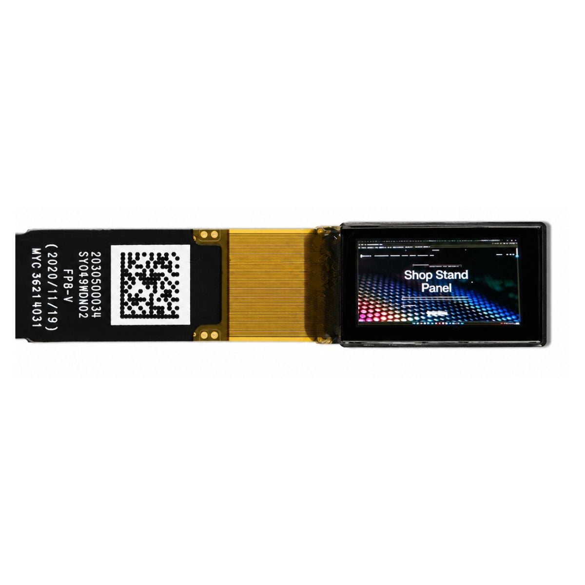
Eye relief is the designed distance between the viewing optics and the eye. Prescription eyewear may increase that distance; whether this reduces the visible field depends on the module's geometry. Compare the specified field of view, exit pupil, and eye relief with the intended wearing position. The same integration issue applies to micro-OLED near-eye displays.
The IPD study reports female values of 51–74.5 mm, with a mean of 61.7 mm, and male values of 53–77.5 mm, with a mean of 64 mm. Those are dataset values, not universal limits or an AR-module acceptance specification [3]. Use the wearer's measured IPD and the vendor's supported adjustment method. Request the module's eyebox and eye-relief measurements with their test conditions; IEC 63145-20-10 addresses optical-property measurement methods for eyewear displays [6].
Do not force a headset against prescription glasses or safety eyewear. This guide concerns optical-engine evaluation, not vision correction or safety certification. Stop the test if viewing is uncomfortable; persistent double vision outside the device needs qualified clinical advice.
Why Do the Left and Right Images Not Line Up?
If each eye sees a clean image but the combined view doubles, check the supported IPD setting, left-right view assignment, and the calibration profile for the exact hardware revision. Physical fit and software eye-spacing settings are related, but one does not automatically correct the other. The relationship between the two views is explained in how AR glasses create stereoscopic images and binocular parallax.
A reset may remove a saved profile; a mismatched profile may apply the wrong correction; swapped views change which image reaches each eye. These are not all cases of calibration data being erased. Confirm the configuration, then run the vendor's user-calibration routine with a static crosshair and edge markers. Do not overwrite factory correction files or swap cables unless the vendor's integration instructions require it.
If a single-eye view still contains a second copy, binocular recalibration alone may not resolve it. Compare the application with the vendor's test content and record whether the duplicate stays at the same location.
Why Does White Text Have Red and Blue Edges?
One possible cause is transverse chromatic aberration (TCA), where magnification varies with wavelength. The FDA describes a measurement method that uses the TCA minimum to locate the eye-point in suitable HMD optics. Its stated limitations include rotationally symmetric optics with measurable TCA, generally found in VR headsets; it is not a universal centering test for AR waveguides [4].
Compare a stationary pattern at the intended viewing position with the same pattern at other permitted positions. Record changes in fringe, clipping, and brightness separately. Neither symmetric edge falloff nor one persistent blurred patch proves a particular manufacturing defect. Different optical-waveguide categories use different optical structures, so ask for a design-specific interpretation of the result. The related contrast, uniformity, and chromatic-aberration measurements also need defined viewing conditions.
Color splitting that appears mainly during motion needs a different check. Microsoft's HoloLens documentation describes temporal color separation in its color-sequential displays when the eyes follow moving content. That device-specific effect should not be diagnosed automatically as static optical misalignment in another module [7].
Why Does the Label Drift Away from Its Target?
A sharp image can still be placed incorrectly in the room. In Microsoft's HoloLens documentation, drift can occur when holograms are far from spatial anchors, especially in unmapped areas. The same documentation distinguishes tracking-related jitter from low-frame-rate judder and head-motion-related swim involving calibration or reprojection. Motion-dependent error therefore does not prove that the room map has been lost [7].
| Test result | What it suggests | Next check |
|---|---|---|
| Head-locked pattern is clear; world-locked target is offset or drifts | A world-placement or stabilization problem is more likely than simple edge clipping | User calibration, target registration, anchor placement, tracking, and reprojection |
| Both views clip or double while the head is still | Viewing geometry, view assignment, calibration, or the display path may be involved | Per-eye static test, supported fit adjustments, and the correct module profile |
| Both look acceptable while still but degrade during motion | Timing, rendering, reprojection, or tracking may be involved | Vendor performance diagnostics and a repeatable motion test |
For camera-based tracking, keep the sensors unobstructed and test in stable, even lighting with visible environmental features. Microsoft's HoloLens guidance explains how very dark or bright conditions and reflective surfaces can impair tracking. Its recommendations are platform-specific, so use your device's operating guidance rather than transferring a HoloLens lighting threshold to every AR engine [8].
When Is It a Depth or Visibility Problem Instead?
A centered image that is hard to fuse is not necessarily geometrically misplaced. A review of XR vision discusses fixed-focus consumer VR headsets, often with virtual-screen distances of 1–2 m, and the conflict between that focus distance and convergence at a different virtual depth. That figure is not a specification for all AR waveguide displays [5]. Check the engine's actual focal distance and the application's disparity settings before choosing a comfortable content depth.
A washed-out image is another separate symptom: poor visibility is not proof of positional error. Compare an ar waveguide display under recorded ambient and display settings, keeping the test content unchanged. Brightness, transparency, and timing affect the viewing result, while the optical see-through light path explains why the real-world background remains visible.
Build a Repeatable Misalignment Test Record
Use the following as a proposed evaluation procedure, not as a report of measurements on a particular product. Keep the pattern, hardware, and software version fixed while changing one variable at a time.
- Capture the baseline. Record the module model, hardware revision, firmware, application version, calibration profile, supported IPD setting, eye relief, ambient conditions, and display brightness setting. Note which eye sees the fault.
- Check fit. Adjust only the permitted wearing controls, then return to the baseline. Record whether the same symptom disappears and reappears.
- Check each eye and the combined view. Use a static crosshair, grid, edge markers, and a short text block. Distinguish clipping, a single-eye ghost copy, binocular doubling, and colored edges.
- Compare reference frames. Observe a head-locked pattern and a world-locked target while still, then repeat a slow, controlled head movement in a clear test area. Record offset, drift, jitter, or motion-only breakup without assigning a cause prematurely.
- Change one configuration item. Follow the vendor's calibration or profile-restoration instructions, then repeat the baseline test. Preserve the before-and-after settings rather than recording only that the result was “better.”
- Send a reproducible support report. Include the pattern, affected eye, conditions, repeatable steps, and remaining fault. If using a through-optics camera, document its position: a camera that is not at the intended eye-point can introduce a measurement error.
The FDA centering method illustrates why measurement setup matters: it uses a high-resolution camera on a three-axis stage and reports testing on four VR headsets, with comparison against maximum-luminance alignment. That is published third-party experimental evidence, not a test of DisplayModule products or proof that the method applies to every waveguide [4].
Do not rebond, polish, heat, or mechanically realign waveguide plates, gratings, or mirrors as a troubleshooting step. Keep the assembly intact and send the test record to the supplier before attempting a repair.
When Should the Optical Engine Be Investigated?
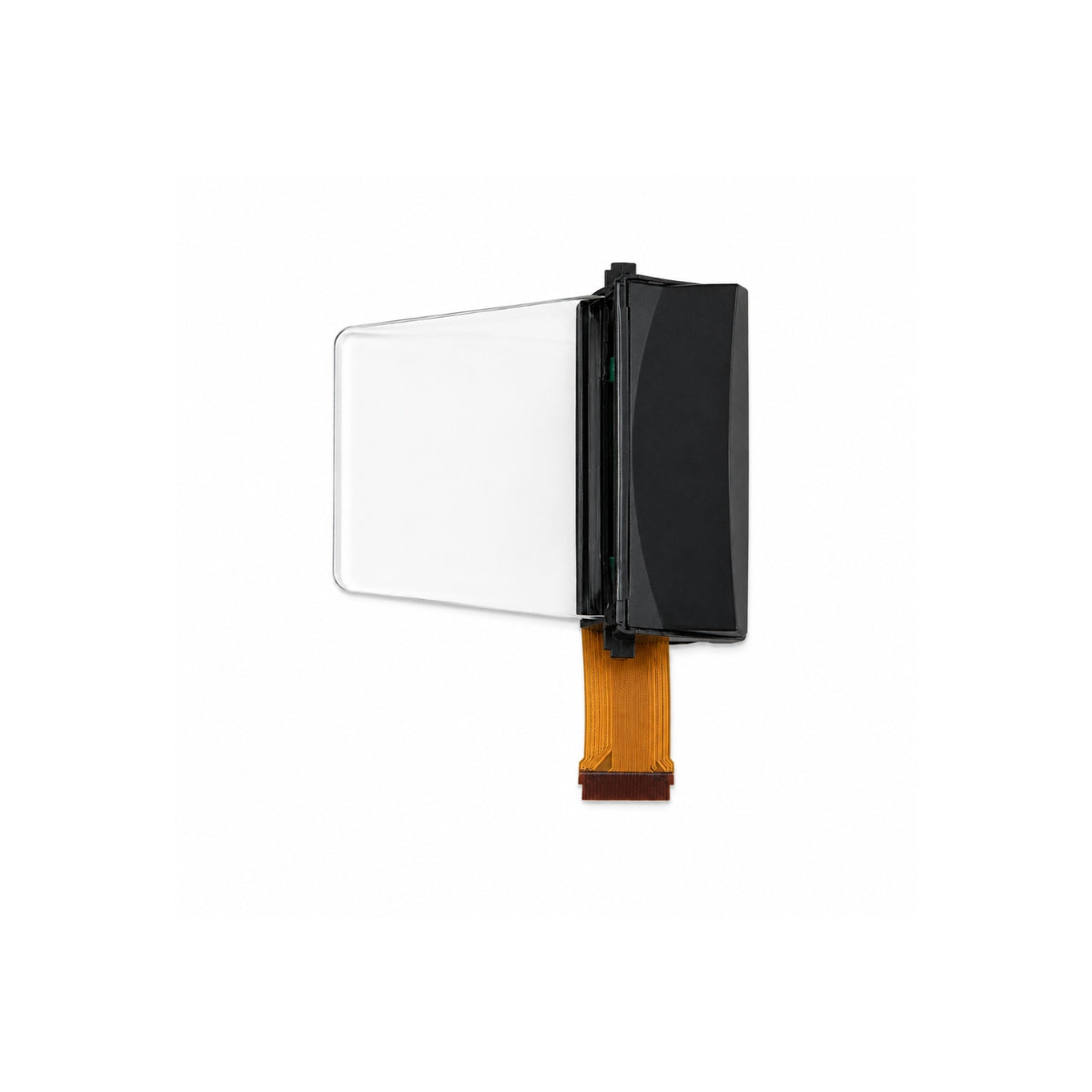
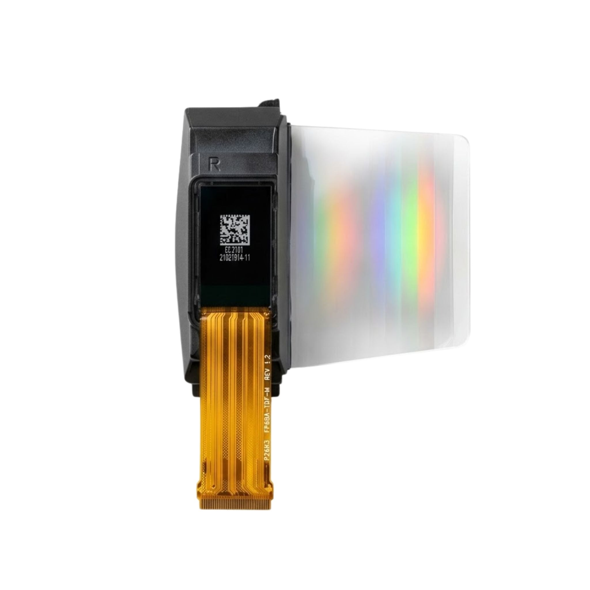
If the fault persists with the vendor's test content, supported fit, and the correct configuration, investigate the engine and its integration without assuming the panel is defective. An ar waveguide display combines a microdisplay, coupling optics, waveguide, mechanics, drive electronics, and calibration. AR display-panel requirements are only one part of that evaluation.
Request measured results and acceptance limits rather than a claim that an image “looks aligned.” IEC 63145-20-10 covers optical-property measurement methods, but citing its public scope does not establish that a product has passed a test or been certified [6]. SID's Information Display Measurements Standard (IDMS) provides a broader display-metrology reference [9].
| Parameter | Evidence to request |
|---|---|
| Eyebox and eye relief | Usable viewing region, measurement position, pupil conditions, and permitted eye-relief range |
| Distortion and color registration | Grid and color-pattern results at defined positions, with the applied correction profile identified |
| Brightness and uniformity | Measurements across the viewing region, ambient conditions, display settings, and left-right comparison where applicable |
| Integration and repeatability | Mechanical datums, mounting instructions, electrical configuration, sample count, and supplier-agreed acceptance limits |
The FDA's IDMS scope entry explicitly includes both see-through AR and non-see-through VR eyewear [10]. SID's Display Week 2022 metrology course describes the addition of near-eye evaluation methods in IDMS version 1.1; use the applicable method and edition when agreeing a test plan [11]. Compare candidate XR optical modules against those requirements, and confirm the current datasheets, drawings, and calibration responsibilities with the supplier.
Need measured data for your shortlist?
Send your eyebox, brightness, and interface requirements and receive matched module datasheets with a project quote.
Request Datasheets and QuoteBottom Line
First decide whether the fault is inside the displayed image or in its placement against the real world. Use fit and per-eye tests for clipping or doubling, then compare static and moving reference-frame tests for placement errors. Evaluate an ar waveguide display against recorded conditions and supplier limits; an unresolved symptom warrants investigation, not an automatic verdict of bad optics or failed tracking.
FAQ
Why is my AR overlay sharp but consistently offset?
Sharpness does not verify spatial alignment. Check user calibration and the application's target registration or anchor transform. Compare the vendor's calibration content with the affected application before changing the optics.
Can recalibration fix an optical ghost image?
Not necessarily. Recalibration can address supported view-alignment errors, but a second copy visible in a single-eye static test needs a separate optical or rendering investigation.
Does one blurry edge mean the waveguide is defective?
No. First reproduce the result at the specified viewing position with the correct profile. If the same area remains affected, send the pattern and setup details to the supplier; the symptom alone does not establish its cause.
What if the problem returns for a different wearer?
Repeat the supported fit and user-calibration procedure for that wearer. Reusing another person's eye-spacing setting or calibration can make a working system appear misaligned.
Sources
- Portland State University, PDXScholar. Guided Modes Through the Dual Perspectives of Geometrical Optics and Wave Equation. Accessed 2026-11-13. Supports the basic total-internal-reflection principle, not product performance.
- University of Arizona, Wyant College of Optical Sciences. Augmented Reality Display Waveguide Design. Accessed 2026-11-13. Course scope covers waveguide and grating design; not a troubleshooting validation study.
- Stanney, Fidopiastis, and Foster. Virtual Reality Is Sexist: But It Does Not Have to Be. Frontiers in Robotics and AI, via NIH PMC. Accessed 2026-11-13. VR-headset research and cited anthropometric IPD data; not a universal AR fit-rate estimate.
- U.S. Food and Drug Administration. Head Mounted Display Eye-box Centering using Transverse Chromatic Aberrations, RST24MX05.1. Accessed 2026-11-13. Camera-alignment method tested on four VR headsets; requires suitable optics with measurable TCA. Not universal waveguide validation or FDA product approval.
- Levi et al. Applications and implications for extended reality to improve binocular vision and stereopsis. Journal of Vision, via NIH PMC. Accessed 2026-11-13. Discusses vergence-accommodation conflict and typical fixed-focus consumer VR examples; the 1–2 m value is not an AR-module specification.
- International Electrotechnical Commission. IEC 63145-20-10:2019: Eyewear display — Fundamental measurement methods — Optical properties. Accessed 2026-11-13. Public scope only; no claim of paid-standard review, product compliance, or certification.
- Microsoft Learn. Hologram stability. Accessed 2026-11-13. Official HoloLens technical documentation covering drift, jitter, judder, swim, reprojection, and temporal color separation. Device-specific behavior is not a specification for every AR module.
- Microsoft Learn. HoloLens environment considerations. Accessed 2026-11-13. Official guidance on lighting, environmental features, and reflective surfaces in camera-based tracking; operating thresholds are platform-specific.
- Society for Information Display, ICDM. Information Display Measurements Standard. Accessed 2026-11-13. Display-metrology reference, not a product test certificate.
- U.S. Food and Drug Administration. Recognized Consensus Standards: ICDM IDMS. Accessed 2026-11-13. Scope includes see-through AR and non-see-through VR eyewear; database inclusion does not approve a particular device.
- Society for Information Display. Display Week 2022: Display Metrology. Accessed 2026-11-13. Historical description of IDMS version 1.1 near-eye evaluation content, not a claim about the latest edition.
더 읽기
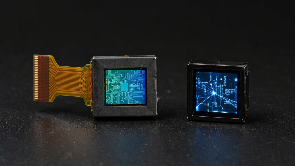
For a full-color EVF or AR prototype, start by evaluating Micro OLED with a matched driver board. For a compact, very bright monochrome AR overlay, evaluate Micro LED. Neither technology wins every...
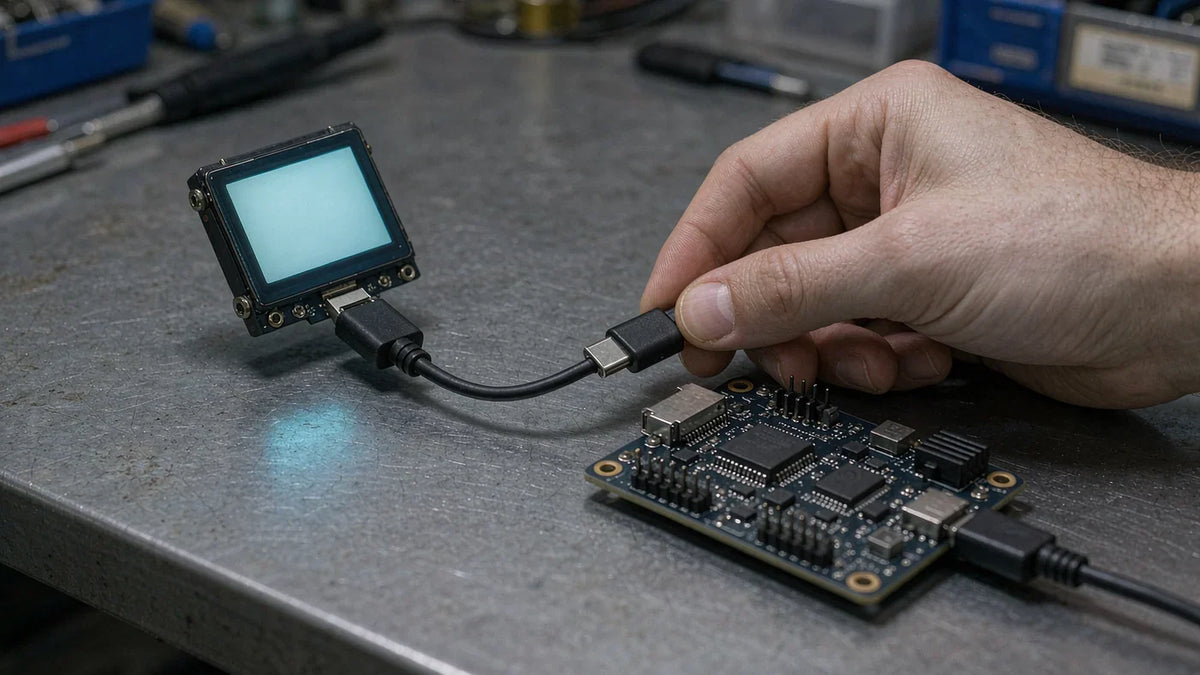
Yes—with a compatible active driver board, not a passive cable. For a MIPI-input Micro OLED, the route covered here is a USB-C source with DisplayPort Alt Mode, an active DisplayPort-to-MIPI DSI br...
댓글 남기기
이 사이트는 hCaptcha에 의해 보호되며, hCaptcha의 개인 정보 보호 정책 과 서비스 약관 이 적용됩니다.