


What is The Use of Waveguides in AR Glasses?
Waveguides in AR glasses route light from micro-OLEDs to eyes via total internal reflection, enabling thin, lightweight form factors. Multi-layer structures (RGB channels) merge images, delivering 50-70° FOV with ~85% transmittance, critical for sharp, wide-field augmented visuals in compact wearables.
Light Paths in Waveguides
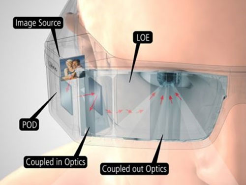
Waveguides in AR glasses function like miniature, complex highways for light, guiding digital images from a micro-display on the temple to the user's eye. Unlike a simple piece of glass, a waveguide's core mechanism is Total Internal Reflection (TIR), which allows light to travel with minimal loss. For TIR to occur, light must strike the waveguide's inner surface at an angle greater than the critical angle, which is typically around 42 degreesfor common optical glass (refractive index ~1.8). This process can bounce a single light ray over 50-100 timeswithin a glass plate often less than 1 mm thick.
For instance, optical efficiency—the percentage of light from the source that actually reaches the eye—is a critical battleground, with figures ranging from a low of <1%for some early designs to over 15%for more advanced implementations.
A larger FOV, say 50 degreescompared to a basic 20-degreeFOV, requires more precise optical structures to handle the wider range of incident angles. Once inside, TIR takes over. The light ray travels within the slab, with its path length determined by the waveguide's thickness and the angle of incidence. A typical path length might be 10-20 mmfrom the in-coupler to the eye box. The most critical part is the out-coupler, which systematically disrupts the TIR condition to direct the light toward the pupil. This can be achieved via surface relief gratings (SRGs), holographic optical elements (HOEs), or other diffractive optics. The design of the out-coupler dictates the eye box—the 3D volume within which the user can see the full image. A larger eye box, for example 12 mm x 8 mm, provides significant comfort, allowing for natural head and eye movements without the image clipping. However, expanding the eye box often comes at the cost of efficiency; doubling the eye box size can sometimes reduce peak brightness by 30% or moredue to the need to distribute the same amount of light over a larger area.
|
Characteristic |
Geometric Waveguide |
Diffractive Waveguide (e.g., SRG) |
|---|---|---|
|
Typical Optical Efficiency |
Higher, often >80(per channel) |
Lower, typically <5% |
|
Color Uniformity |
Excellent, minimal color separation |
Challenging; can exhibit rainbow effect |
|
FOV Capability |
Good, can support up to ~55 degrees |
Very Good, can exceed 60 degrees |
|
Manufacturing Complexity |
High-precision laminated glassassembly |
Mass-produced via nanoimprint lithography |
|
Relative Cost |
High (~300per unit at scale) |
Lower (~150per unit at scale) |
A key metric for the light path is see-through clarity, measured as wavefront error or optical distortion, which should ideally be less than 0.1%to avoid causing user eye strain. Furthermore, light lossis not uniform; it can be wavelength-dependent. For example, a diffractive waveguide might have an efficiency of 5%for green light but only 2%for blue light, leading to an unbalanced color gamut and reducing the effective contrast ratioof the virtual image. Modern designs combat this by stacking multiple waveguide layers—one for each primary color (Red, Green, Blue). This stacking, however, increases thickness and weight; a three-layer stacked waveguide can add 0.5 mmto the overall lens thickness and increase weight by 5-10 grams, pushing the design against the critical consumer threshold of <30 gramsfor the optical engine. 
Boosting Image Sharpness
A key metric here is angular resolution, measured in pixels per degree (PPD). The human eye can resolve approximately 60 PPD. Many early AR waveguides struggled to achieve even 35 PPD, resulting in pixelated text and blurry edges. Modern waveguide designs specifically target >45 PPDto make reading text practical. Another critical sharpness parameter is the Modulation Transfer Function (MTF), which quantifies contrast retention at increasing spatial frequencies. A good waveguide design for consumer AR will maintain an MTF value of >0.3 at 20 cycles/degree, ensuring that fine details in the virtual image remain distinct and not "washed out."
Diffraction-based waveguides, which use nanoscale gratings, are particularly susceptible to a phenomenon called chromatic dispersion. This occurs because the grating's efficiency varies with wavelength; green light (550nm) might be directed with 85%efficiency, while red (650nm) and blue (450nm) drop to ~70%. This 15%variation causes color fringing, where a white line might show a slight red or blue shadow, effectively reducing the effective resolution.
The waveguide itself has a limited angular bandwidth, meaning it can only efficiently transmit light arriving within a specific cone of angles from the micro-display. If the micro-display's output cone is even 5 degreeswider than the waveguide's optimal input, the edges of the image will appear dimmer and less sharp. This coupling loss can reduce peripheral sharpness by a perceptible 15%. Furthermore, the exit pupil expanderin the waveguide, which creates the large eye box, can introduce a "screen door" effect if its periodic structure (e.g., grating lines with a 500nm pitch) becomes visible. The fill factor of this structure must be engineered to be finer than what the eye can resolve at a typical 30-40 cmviewing distance of the virtual image.
|
Sharpness Factor |
Diffractive Waveguide |
Geometric Waveguide |
|---|---|---|
|
Primary Artifact |
Chromatic Aberration ("Rainbow Effect") |
Ghosting / Wavefront Distortion |
|
Typical MTF @ 20 cy/deg |
0.25 - 0.40 |
0.35 - 0.50 |
|
Impact of Eye Box Expansion |
Significant sharpness fall-off (~20%) at edges |
More uniform sharpness across eye box (<10%fall-off) |
|
Dependence on Micro-display |
High; requires precise <3°angular alignment |
Moderate; more tolerant of input angles (~8°) |
A larger Field of View (FOV)often forces a trade-off with angular resolution; doubling the FOV from 30° to 60°without increasing the micro-display's pixel count will cut the PPD in half. Therefore, high-sharpness, wide-FOV designs require extremely high-density micro-displays with pixel pitches below 5 microns. The waveguide must then preserve this intrinsic resolution with minimal degradation. Every 1%reduction in MTF can make the difference between text that is easy to read for 30 minutesand text that causes eye strain in under 5 minutes.
Making Glasses Lightweight
Consumer tolerance for wearable devices is exceptionally low; studies and user feedback consistently point to a sub-80-gramthreshold for the entire device to be considered comfortable for periods exceeding 2-3 hours. Traditional optical architectures like BirdBath place the heavy projector module directly in the lens frame, often resulting in a front-weight of 50-70 grams, creating an imbalanced and neck-fatiguing experience. By acting as a passive conduit, the waveguide itself can be incredibly thin—often under 1.5 millimetersthick and weighing 10-15 gramsper lens.
The substrate material itself is a key variable. While most high-performance waveguides use B270 or D263T eco glasswith a density of about 2.5 g/cm³, research is intensely focused on optical polymers. These polymers can have a density as low as 1.1-1.3 g/cm³, offering a potential 50% reduction in the waveguide's weight. The trade-off, however, is significant: polymers generally have a lower refractive index (often <1.6), which can limit the Field of View (FOV), and they are more susceptible to scratching and thermal expansion, which can distort the image in environments with temperature swings exceeding 30°C. Another critical factor is the optical architecture's efficiency. A waveguide with only 1% optical efficiencyforces the use of a much brighter micro-display, which in turn requires a larger battery and more powerful electronics. Improving that efficiency to just 5%can reduce the power budget by 300-400 milliwatts, allowing for a battery that is 15-20% smaller and lighter, creating a virtuous cycle of weight reduction throughout the entire device.
The impact of waveguide-driven weight reduction can be broken down into its direct and indirect effects:
-
Direct Mass Reduction of the Optical Engine:The core optical combiner (the waveguide lens) is a flat, passive element. A typical waveguide combiner might weigh 12-18 grams, whereas a comparable BirdBath combiner with its complex prism and mirror assembly can weigh 25-35 grams. This direct ~15-gram savingper unit is a substantial starting point.
-
Enabling Balanced Weight Distribution:This is the most significant benefit. By moving the projector module (weighing 15-25 grams) to the temple, the weight on the nose bridge is dramatically lowered. Instead of ~60 gramsconcentrated on the front, the frame front weight can be reduced to ~15 grams(just the waveguide and frame), with the remaining mass distributed evenly along the 140-160 mmlength of the temple arms. This improves the product's moment of inertia, making it less likely to slip during rapid head movements, which can occur at accelerations over 2 m/s².
-
Compatibility with Standard Frames:The thin, flat profile of waveguides allows them to be integrated into form factors that closely resemble standard prescription glasses, which typically weigh 30-50 grams. This is a psychological and physical tipping point for adoption. A waveguide-based AR device weighing 75 gramsfeels familiar, while a bulkier optical design weighing 120 gramsis immediately categorized as a specialized tool, limiting its wearability to short, 30-45 minutesessions.
Working with Microdisplays
A waveguide has a fixed étendue acceptance limit. A micro-display with a large area (e.g., 0.7-inch diagonal) but low angular spread might have the same étendue as a smaller, brighter display (e.g., 0.3-inch) with a wider spread. The challenge is to maximize the transfer of light from the micro-display into the waveguide's narrow acceptance cone, which is often less than ±5 degrees. This coupling efficiency is paramount; even with a waveguide boasting 15%system efficiency, if the coupling loss at the input is 50%, the overall efficiency plummets to 7.5%, directly demanding a brighter—and more power-hungry—micro-display to compensate. For a target virtual image brightness of 2000 nitsperceived by the user, a system with 7.5%total efficiency requires the micro-display to emit over 26,000 nits, pushing the limits of current technology and battery life.
The first is angular color uniformity. Micro-displays like LCoS (Liquid Crystal on Silicon) or OLEDoS (OLED on Silicon) emit light across a range of angles. A diffractive input grating, however, has an efficiency that peaks at a specific angle for each color. This can cause a green image in the center of the FOV to shift towards red or blue at the edges, a distortion that can be measured as a color shift exceeding 0.02 in u'v' color coordinatesacross a 40-degreeFOV. Secondly, the pixel sizeof the micro-display directly limits the theoretical angular resolution(PPD) of the system. A display with a 5-micron pixel pitchcoupled into a waveguide producing a 30-degreeFOV results in a maximum of approximately 30 PPD(calculated as FOV / (pixel size / eye relief) ). To achieve a sharper 60 PPDin a 50-degreeFOV requires pixel pitches below 3 microns, which are at the forefront of micro-display manufacturing, with yields often below 20%, contributing significantly to high costs. The physical alignment tolerance is also incredibly tight; a lateral misalignment of just 10 micronsbetween the micro-display and the input grating can cause a 5% drop in coupling efficiency and introduce image distortion.
The choice of micro-display technology creates a cascade of implications for the entire optical system:
-
LCoS (Liquid Crystal on Silicon):This technology is known for its high resolution, with products readily available at 1920x1200resolution. However, it requires a separate white LED light source and a polarizing beamsplitter, adding 5-8 gramsof weight and consuming 300-500 milliwattsof additional power. Its reflectance efficiency is typically around 60%, meaning 40%of the light is lost before it even enters the waveguide.
-
Micro-OLED (OLEDoS):This is an emissive technology, meaning it generates its own light. This eliminates the need for a backlight, saving weight and power. Modern Micro-OLEDs can achieve phenomenal peak brightnesses exceeding 10,000 nitson a 0.7-inchpanel with a power draw of 0.5-1 watt. Their primary limitation for waveguides is a lower fill factor (the gap between pixels), which can be as high as 20%, potentially contributing to a "screen door" effect if not properly managed by the waveguide's output expander.
-
Micro-LED:This emerging technology promises the best of both worlds: the emissive nature of OLED with ultra-high brightness (>1,000,000 nits) and efficiency. The monumental challenge is mass transfer, the process of placing millions of microscopic LED chips onto a silicon backplane. Defect rates for a 1280x720resolution display are still prohibitively high, with yields below 5%, making a single micro-display unit cost upwards of $1000, confining it to military and enterprise applications for the near future.
A micro-display with a native contrast of 10,000:1can see that value reduced to 100:1in the final virtual image if the waveguide's optical surfaces are not perfectly clean and free of scatter. The data interface between the display driver and the glasses' main processor is also a bottleneck; driving a 1920x1080panel at 90 Hzrequires a data rate of over 3 Gbps, which consumes significant power and generates heat that must be dissipated away from the user's temple.
Types of Waveguide Designs
The choice between them is a fundamental trade-off involving manufacturing cost, optical performance, and mass-production scalability. For instance, a simple one-dimensional pupil expansion waveguide might have only 3 or 4optical surfaces to manage, while a full two-dimensional expansion system for a large eye box can have complex nanostructures with feature sizes smaller than 400 nanometers. The performance gaps are significant: optical efficiencycan vary from over 80%for a single-color geometric design to less than 1%for some early diffractive prototypes.
|
Characteristic |
Geometric (Reflective) Waveguide |
Diffractive Waveguide |
|---|---|---|
|
Core Technology |
Microscopic partial mirrors embedded in glass |
Surface Relief Gratings (SRG) or Volumetric Holograms |
|
Typical Optical Efficiency |
High, 40% - 80%per color channel |
Low to Moderate, 3% - 15%for full-color |
|
Image Quality Hallmark |
Excellent color fidelity, high contrast |
Potential for "rainbow" artifacts, lower contrast |
|
Manufacturing Method |
Precision polishing & thin-film coating |
Nanoimprint lithography (NIL) |
|
Scalability & Cost |
Lower scalability, higher cost (~$200+) |
High scalability, lower cost at volume (~100) |
The defining difference lies in how they manipulate light. Let's break down the key types:
-
Geometric Waveguides:The light then travels via Total Internal Reflection (TIR) until it encounters a series of partially reflective surfaceswith a reflectivity of perhaps 20%each. These surfaces "leak" a small, consistent portion of the light toward the eye at each bounce. The advantage is physics-based color accuracy; since reflection is agnostic to wavelength, color uniformity is excellent, with a color gamut covering >95% of DCI-P3. The major challenge is manufacturing the embedded mirrors with the required λ/4 surface flatness(about 125 nanometersfor green light) and aligning them with an angular error of less than 0.1 degrees. This process is slow and has a final yield that can be as low as 20-30%for complex designs, explaining the high cost.
-
Diffractive Waveguides (Surface Relief Grating - SRG):A key design parameter is the grating period, which is typically between 300-500 nm. The primary advantage is the ability to perform two-dimensional pupil expansionin a single, flat layer, creating a large eye box (e.g., 15x10 mm) from a very compact input. The major drawback is chromatic dispersion. Because the grating equation is wavelength-dependent, different colors are diffracted at slightly different angles. This can cause a 5-10 pixelshift between the red and blue color channels at the edge of a 50-degreeFOV, manifesting as the notorious "rainbow effect." Efficiency is also a challenge; a single-layer, full-color SRG waveguide typically has an efficiency of only 3-5%, meaning over 95%of the light from the micro-display is lost.
-
Holographic Waveguides (Volume Holographic Grating - VHG):Within this layer, an interference pattern is recorded holographically, creating a Bragg gratingthat is highly selective to a specific angle and wavelength of light. This selectivity is their key advantage: VHGs can achieve theoretical peak efficiencies of over 90%for their target wavelength and angle. This makes them ideal for laser-based display systems.
Why Users Notice Differences
The most obvious differentiator is brightness. In a typical office environment with an ambient light level of 300-500 lux, a virtual image needs to sustain at least 500 nitsof brightness to remain clearly visible. A waveguide system with 5% optical efficiencypaired with a micro-display emitting 10,000 nits can just meet this threshold. However, step outside on a cloudy day (5,000 lux), and that same image becomes nearly impossible to see, requiring a system brightness of over 2,000 nits—a target that many waveguide systems simply cannot achieve without draining their battery in under 60 minutes.
When a diffractive waveguide exhibits a 0.03 deviation in the u'v' color coordinatefrom the center to the edge of the 40-degreeFOV, the user may not articulate "chromatic aberration," but they will report that "text looks colored and fuzzy at the edges," making it difficult to read a paragraph of text for more than a few minutes. This effect is quantified as eye strain, reducing comfortable usage sessions from a target of 2-3 hoursdown to under 30 minutes.
The physical design and comfortare equally immediate. A pair of AR glasses weighing 75 gramswith a 40/60 front-to-back weight distributioncan be worn for an entire workday with minimal adjustment. In contrast, a device weighing 110 gramswith 70%of its weight on the front of the frame will create pressure points on the nose and behind the ears, causing discomfort that becomes noticeable within the first 15-20 minutesof use. The waveguide's ability to enable a slim, <15 mmthick temple profile is a direct contributor to this comfort.
Furthermore, the eye box sizeis a critical usability metric. A small 8x6 mmeye box forces the user to keep their head unnaturally still; a slight shift of the glasses by just 5 mmcan cause the image to clip or disappear entirely. A larger 12x10 mmeye box, enabled by advanced pupil expansion, provides the ~3-4 mmof movement leeway that makes the device practical for real-world activities like walking or turning your head, where g-forces can easily exceed 1.5 m/s².
Read more
BOE's specially developed for AR 0.39 inch micro-OLED display start to work. It means that AR glasses will usher in a new era of price reduction.
DisplayModule published a XR development Kit. Do It Youself yours XR world!
Leave a comment
This site is protected by hCaptcha and the hCaptcha Privacy Policy and Terms of Service apply.