


Different Categories of Optical Waveguides in the AR Field
Waveguides for light can primarily be classified into two categories: Geometric Waveguides and Diffractive Waveguides.
Geometric Waveguides, also known as array waveguides, achieve image output and enlargement of the eye box through stacked array reflectors.
On the other hand, Diffractive Waveguides mainly involve the use of surface relief grating waveguides fabricated through photolithography, as well as volumetric holographic grating waveguides constructed based on holographic interference technology.
This technology is still under development. It demonstrates good color performance, however, currently there are significant restrictions on the Field Of View (FOV).
Geometric Waveguide
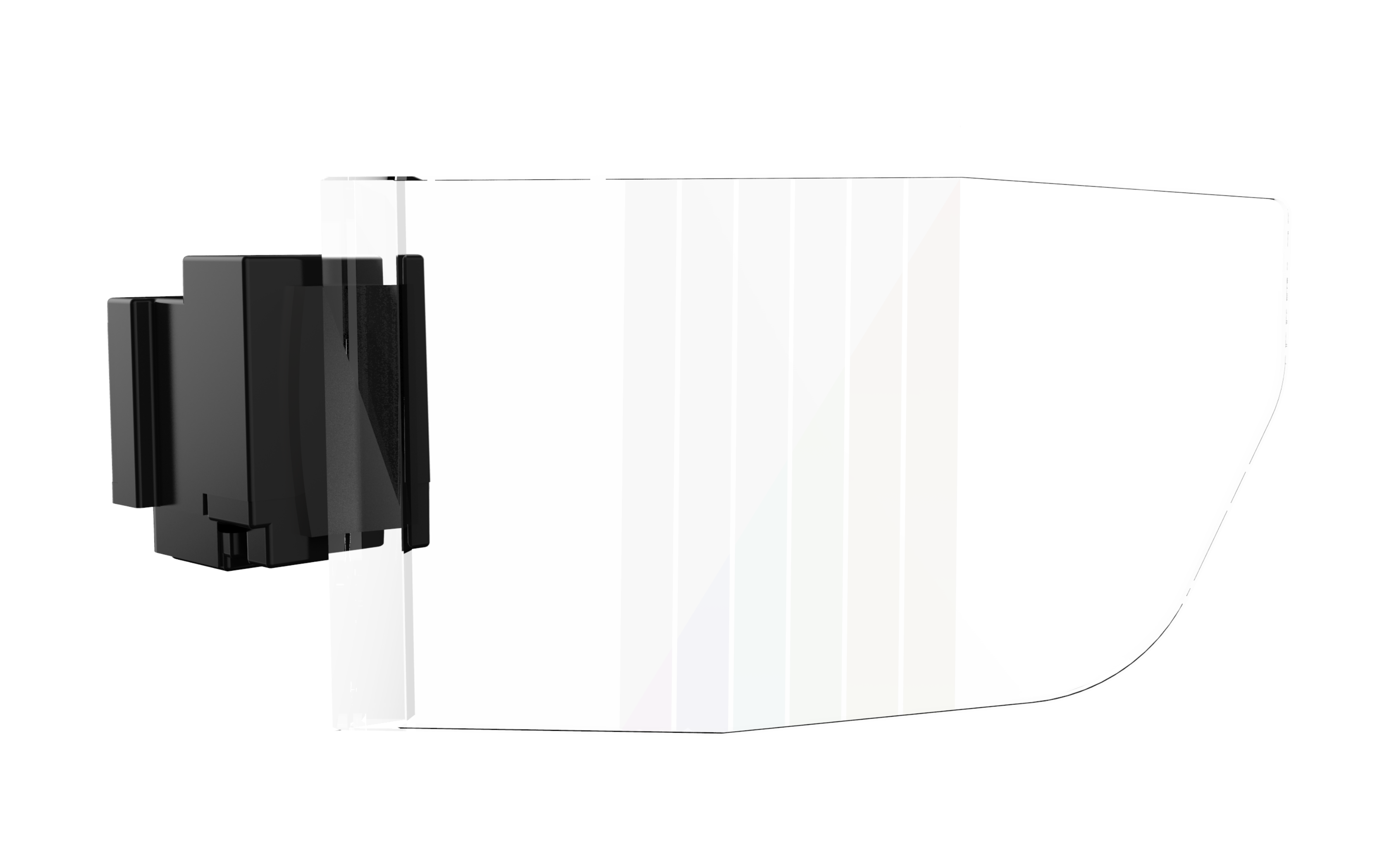
Light coupled into a waveguide usually enters through a reflector or a prism. After multiple total reflections, when the light reaches the front of the glasses, it encounters a "partially reflective, partially transmissive" mirror array. This is the structure where light is coupled out of the waveguide, also known as the "beam combiner" in geometric waveguides.

The "partially reflective, partially transmissive" (more accurately, "partially transmissive, partially reflective") mirror is embedded into a glass substrate and forms a specific angle with the transmitted light path. Each mirror reflects part of the light out of the waveguide into the eye, while the remaining light is transmitted further into the waveguide. This remaining light then encounters another "partially reflective, partially transmissive" mirror, repeating the "reflection-transmission" process, until the final mirror in the array reflects all remaining light out of the waveguide into the eye.
In traditional optical imaging systems, an image usually only has one "exit", called the exit pupil. Here, the "partially reflective, partially transmissive" mirror array effectively replicates the exit pupil horizontally, with each pupil outputting the same image. This way, the eye can see the image even when moving horizontally. This is the one-dimensional exit pupil expansion technology (1D EPE).
To elaborate, if a 4 mm diameter light beam enters the waveguide, and since the waveguide only transmits without enlarging or reducing the image, the exit pupil is also a 4 mm light beam. In this case, the center of the human eye pupil can only move within this 4 mm range and still see the image.
This can be a problem, as the pupil distance for different genders and ages can range from 51 mm to 77 mm. If the optical center of the near-eye display system is designed based on the average pupil distance (63.5 mm), it means that a large number of people will not be able to see a clear image or receive any image at all when wearing the glasses.
With the exit pupil expansion technology, the eye box range can usually be expanded from the initial 4 mm to more than 10 mm. You might wonder, won't multiple exit pupils cause the eye to see duplicate images? Don't worry, the exit pupil plane is just the "Fourier plane" of the image. The eye pupil captures the complete image information from this plane and the eye's inherent "lens" (the lens) transmits the exit pupil plane to the real "image plane" (retina). Therefore, light from the same angle will still converge to the same pixel (visual cell), and there will be no duplicate images.
This may be a bit difficult to understand, but it's the essence of why exit pupil expansion technology is feasible. The enlargement of the eye box has solved many issues in product design, such as mechanical design tolerances, product specification numbers (whether male and female versions are needed), user interaction experience, etc., greatly pushing the realization of consumer-level AR glasses.
However, there's no such thing as a free lunch. The replication of the exit pupil leads to an increase in the total light output area, naturally reducing the amount of light seen at each exit pupil location. This is one of the reasons why waveguide technology has lower light efficiency than traditional optical systems.
Geometric waveguides use traditional geometric optical design concepts, simulation software, and manufacturing processes, and do not involve any micro or nanoscale structures. Therefore, image quality including color and contrast can reach very high standards.
However, the manufacturing process is quite complex, including one step of coating the "partially reflective, partially transmissive" mirror array. As light becomes less and less during transmission, each of the five or six mirrors in the array needs a different reflectance-transmission ratio (R/T) to ensure that the light output throughout the eye box range is uniform.
Furthermore, since light transmitted in geometric waveguides is usually polarized (due to the working principle of LCOS microdisplays), the number of coating layers for each mirror may reach a dozen or even tens of layers. In addition, these mirrors are stacked together after coating and bonded with special glue, then cut into the shape of a waveguide at a specific angle. In this process, the parallelism between the mirrors and the angle of the cut can affect the image quality.
Therefore, even if each step of the process can achieve a high yield rate, the total yield rate of these dozens of steps combined is a challenge. Any failure in a process step may cause imaging defects, common issues being background black stripes, uneven light output brightness, and ghost images.
Also, although the mirror array has become almost "invisible" with process optimization, vertical stripes (i.e., the mirror array) can still be seen on the lens when the light machine is turned off, potentially blocking some of the external view and affecting the aesthetics of the AR glasses.
Diffractive Waveguide
In order for the virtual image produced by a light engine to be transmitted to the human eye via an optical waveguide, two processes are required: the coupling-in and coupling-out of light. In geometric optical waveguides, these processes are achieved using traditional optical elements like prisms or semi-reflective mirror arrays. While this method is straightforward, it presents challenges in terms of physical dimensions and manufacturing processes.
In diffractive optical waveguides, the traditional optical structures are replaced by flat diffractive gratings. This shift towards flatter, nanoscale structures represents a broader trend in optical technology.
So, what is a diffractive grating? Simply put, it's an optical element with a periodic structure, which may either consist of peaks and valleys embossed onto the surface of a material, or interference fringes created within a material by holographic techniques. These structures result in periodic changes in the refractive index within the material.
These periodic structures are typically on the micron or nanometer scale, roughly comparable to the wavelength of visible light (~450-700nm), enabling effective manipulation of light.
Diffractive gratings "split" light in two dimensions. Suppose a single wavelength of green light is incident on the grating. It will be divided into several diffraction orders, each propagating in a different direction. This includes both reflected and transmitted orders of light, with the diffraction angles of each order determined by the incident angle of the light and the period of the grating.
By adjusting other parameters of the grating (such as the refractive index of the material, the shape, thickness, and duty cycle of the grating), the diffraction efficiency of a certain order (i.e., a certain direction) can be maximized. This way, most of the light will propagate primarily in this direction after diffraction.

Besides splitting light into different diffraction orders, diffractive gratings also exhibit dispersion, meaning that for a given grating period, different wavelengths will have different diffraction angles. For example, if white light is incident on the grating, longer-wavelength light will have larger diffraction angles. This dispersion effect is seen in both reflective and transmitted diffractions.
Does this seem familiar? You might recall playing with prisms as a child, which also split white sunlight into a spectrum, or "rainbow". The difference is that this splitting is due to refraction, not diffraction. The image below provides a direct comparison between the dispersive effects of a diffractive grating (including multiple diffraction orders and dispersion) and a prism. You can see that the diffractive grating, which splits light into different diffraction orders each with its own dispersion, is far more complex than a dispersive prism.
Read more
In the world of virtual and augmented reality, developers are constantly seeking new ways to create immersive and engaging experiences for users. With the advent of XR (Extended Reality) technol...

With rapid advancements in technology, AR has found a valuable application in underwater equipment, significantly enhancing the diving experience and bringing a whole new dimension to underwater e...
Leave a comment
This site is protected by hCaptcha and the hCaptcha Privacy Policy and Terms of Service apply.