
XR / XL · glass terminals
Pin 41 is the right glass terminal XR. Pin 43 is the left glass terminal XL.

Popular Products
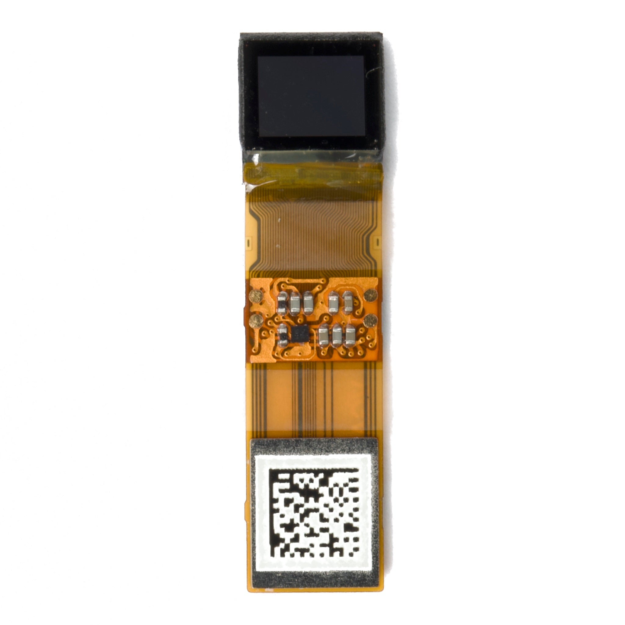
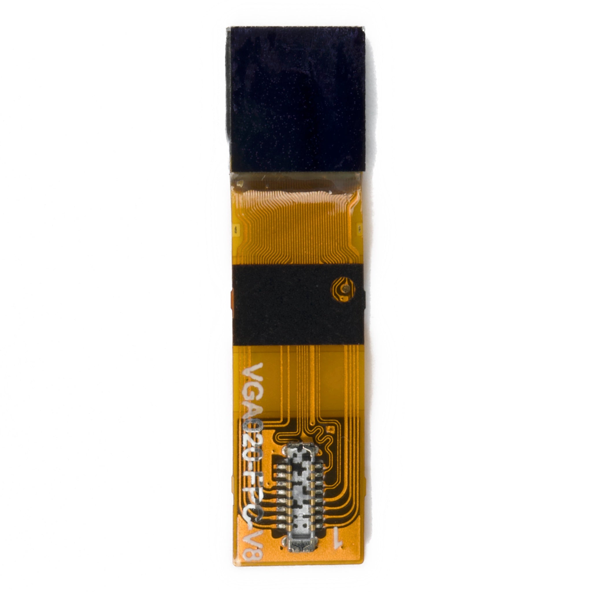
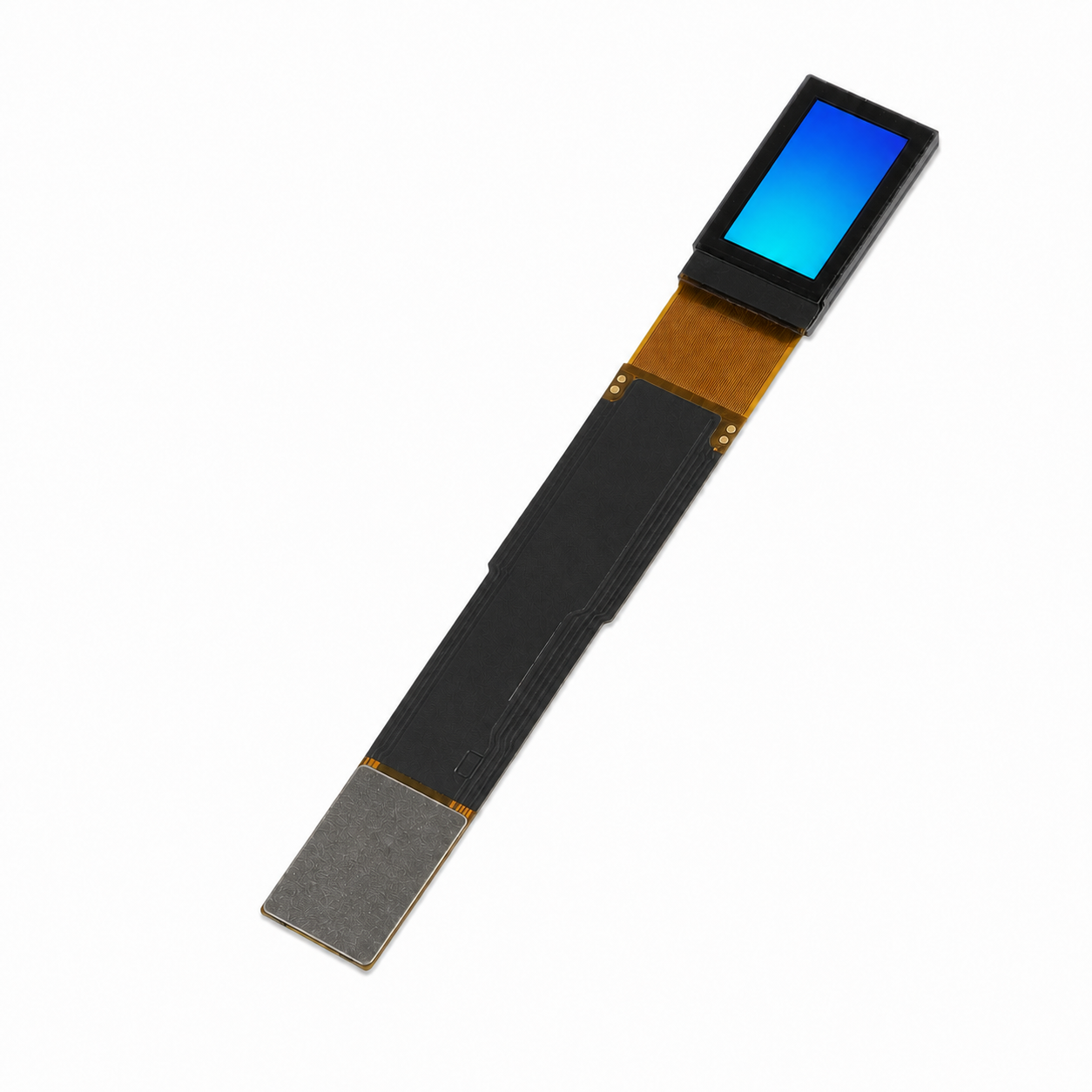
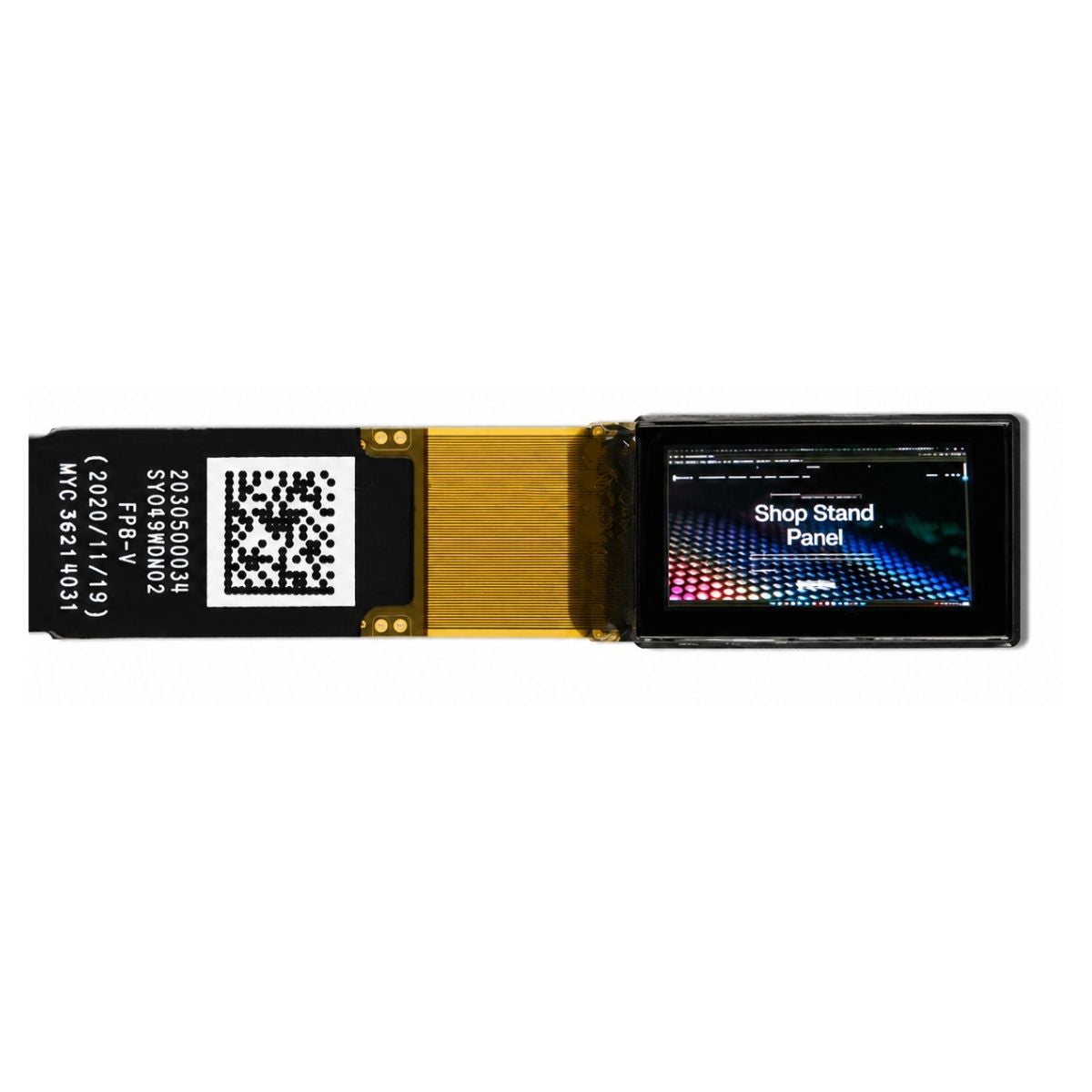


1.77" TFT Display 128x160 Transmissive - SPI, MCU, RGB
DM-TFT18-310
Combine a compact colour interface with resistive-touch input. DM-TFT18-310 brings a 128 × 160 TFT and four touch electrodes together in a 1.77-inch, 9.0 g assembly.
Choose MCU, serial or RGB for the image path. The host provides separate touch acquisition and coordinate calibration for the installed screen orientation.
 + Click to enlarge
The touch layer exposes four resistive electrodes on the same flexible connection as the display. Their electrical roles are independent of the selected MCU, serial or RGB image interface.
Pin 41 is the right glass terminal XR. Pin 43 is the left glass terminal XL.
Pin 42 is the bottom film terminal YD. Pin 44 is the top film terminal YU.
An external acquisition circuit reads the resistive panel. The application calibrates and maps those measurements to its display coordinate system.
This connection exposes the touch electrodes themselves. It does not provide a packet-based I²C touch interface, and the ILI9163 display controller is responsible for the image path.
Touch-terminal reference →The display and touch layer are supplied as one 9.0 g module; the host turns the electrode measurements into application input.
Use the portrait image area for the application’s labels, values and controls. The 65K-colour display provides the image; control size and behaviour are defined by the application.
Map and calibrate acquired coordinates for the installed image orientation. A rotation in the application needs the corresponding touch-coordinate mapping.
Use the DM-TFT18-310 drawing for panel thickness, outline and FPC placement. Its touch assembly must fit the enclosure as a whole.
| Parameter | Specification |
|---|---|
| Product model | DM-TFT18-310 |
| Display size | 1.77 inch |
| Resolution | 128 × 160 pixels |
| Display connection | MCU / 3- or 4-wire SPI / 16- or 18-bit RGB |
| Controller / panel | ILI9163 |
| Display colours | 65K |
| Touch configuration | Four-terminal resistive touch |
| Supply | 2.5–4.2 V; 3.3 V typical |
| Luminance | 300 cd/m² minimum; 360 cd/m² typical |
| Operating / storage temperature | −20 to +70 °C / −30 to +80 °C (absolute maximum ratings) |
The display supports 8-, 9-, 16- or 18-bit MCU operation, 3-wire or 4-wire serial, and 16-bit or 18-bit RGB. The IM, RCM1 and SPI4W pins select the operating mode.
RGB transfers use the pixel bus with PCLK, DE, HSYNC and VSYNC. The touch terminals remain independent of the chosen image interface, allowing touch sampling and screen updates to be implemented as separate host functions.
The display’s mode-select pins allow the image connection to be chosen for the host hardware. Touch acquisition retains the same four-terminal connection across these display modes.
IM1/IM0 combinations 00, 01, 10 and 11 select these four parallel widths respectively. IM2 selects parallel operation at 1.
IM2 = 0 selects serial operation. SPI4W = 1 selects 3-wire serial; SPI4W = 0 selects 4-wire serial.
RCM1 = 1 selects RGB, with PCLK, DE, HSYNC and VSYNC serving the image timing. RCM1 = 0 selects the MCU interface.
Mode selection is a hardware configuration as well as a firmware choice. The module’s pin assignment and initialization must describe the same display connection.
Display-mode reference →Logic voltage is 2.5–4.2 V, with 3.3 V typical and 1.5 mA typical digital operating current at VDD = 3.3 V. The three-LED backlight uses 3.2 V typical forward voltage and 60 mA typical forward current.
Luminance is 300 cd/m² minimum and 360 cd/m² typical. Contrast is 400:1 minimum and 500:1 typical. The 1.5 mA figure describes the display electronics; backlight current is a separate load in the system power budget.
The optical response of the TFT is one component of the complete user-interface response. Touch sampling, application processing and image transfers add their own timing.
Combined rising and falling optical response is 8 ms typical and 16 ms maximum. This specification applies to the liquid-crystal transition.
The illumination-uniformity specification complements the minimum and typical luminance figures; it does not describe touch accuracy.
Top, left and right angles are 35° minimum and 45° typical. The bottom direction is 10° minimum and 20° typical.
For a touch-operated product, the installed viewing angle and the host’s coordinate mapping should use the same physical screen orientation. The preferred viewing direction is 12 o’clock.
Optical-response reference →No. Pins 41–44 expose XR, YD, XL and YU resistive electrodes. A separate acquisition circuit reads the panel, and the host application calibrates the resulting coordinates to the installed orientation.
The four touch terminals retain their roles. RGB image operation uses RCM1 = 1 and the pixel/timing connections, while touch acquisition remains on XR/YD/XL/YU. Configure the display and touch paths separately.
Use the DM-TFT18-310 mechanical drawing for the complete touch stack and FPC route. This SKU is specified at 9.0 g. A common resolution or controller does not establish the same enclosure fit as a non-touch panel.
For DM-TFT18-310 touch support, provide the XR/YD/XL/YU wiring, acquisition-circuit model and coordinate orientation. Include the selected image interface separately so touch measurements can be distinguished from display transfers.
Specify the 9.0 g touch version and the enclosure space around the FPC when requesting a quote. Evaluate the sample with the intended touch-reading circuit and installed screen orientation.
The DM-TFT18-310 datasheet identifies the four touch electrodes, selectable image interfaces and complete touch assembly. The DmTftLibrary is provided as a separate software resource.