









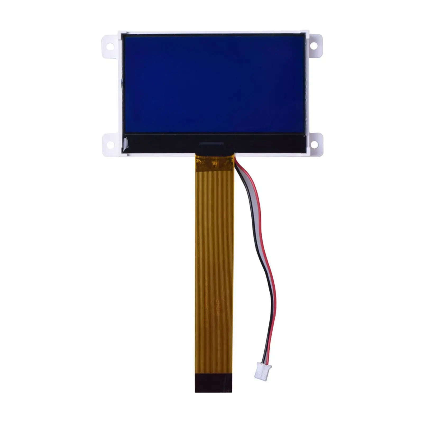
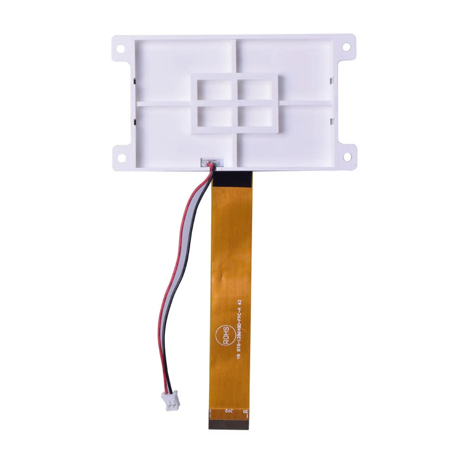


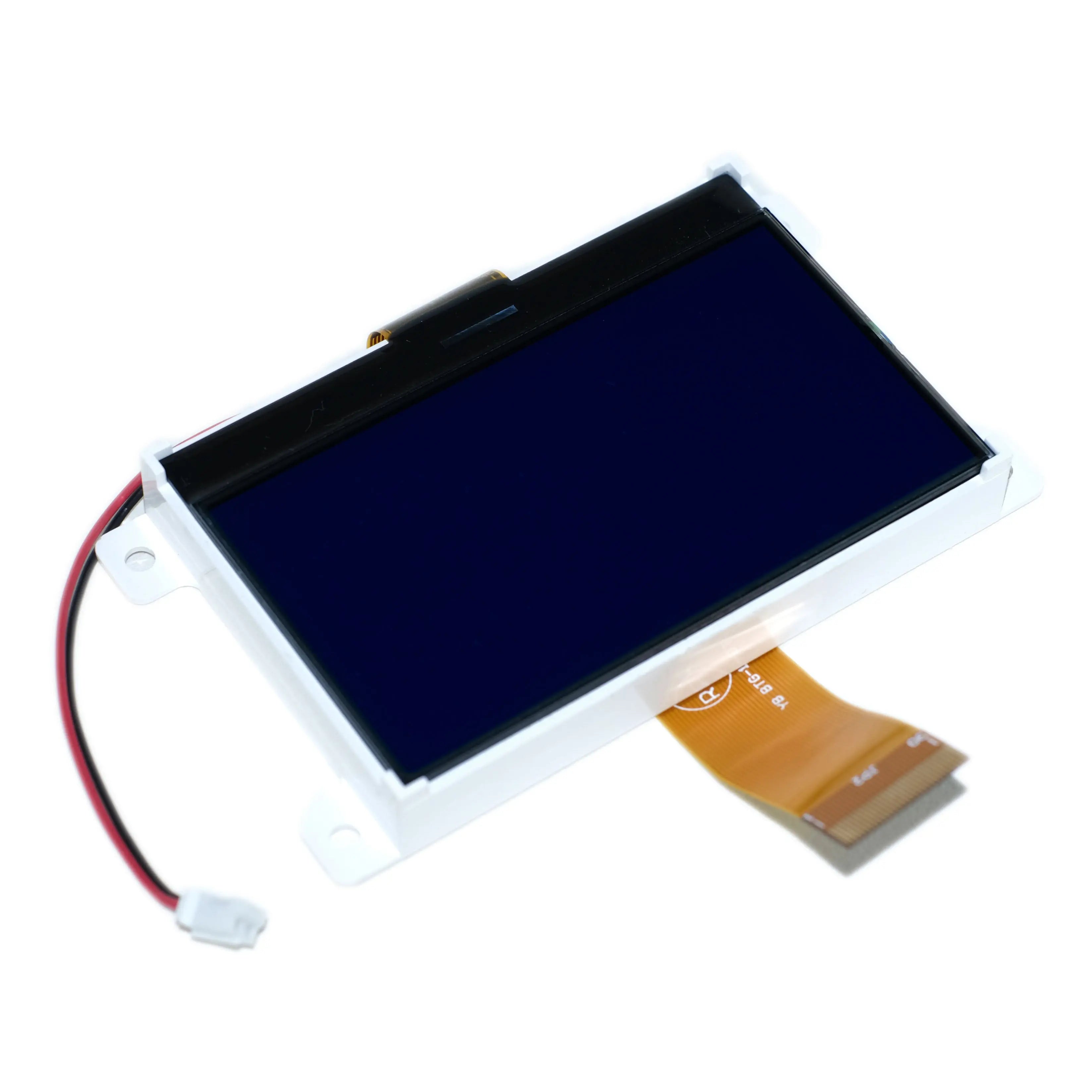
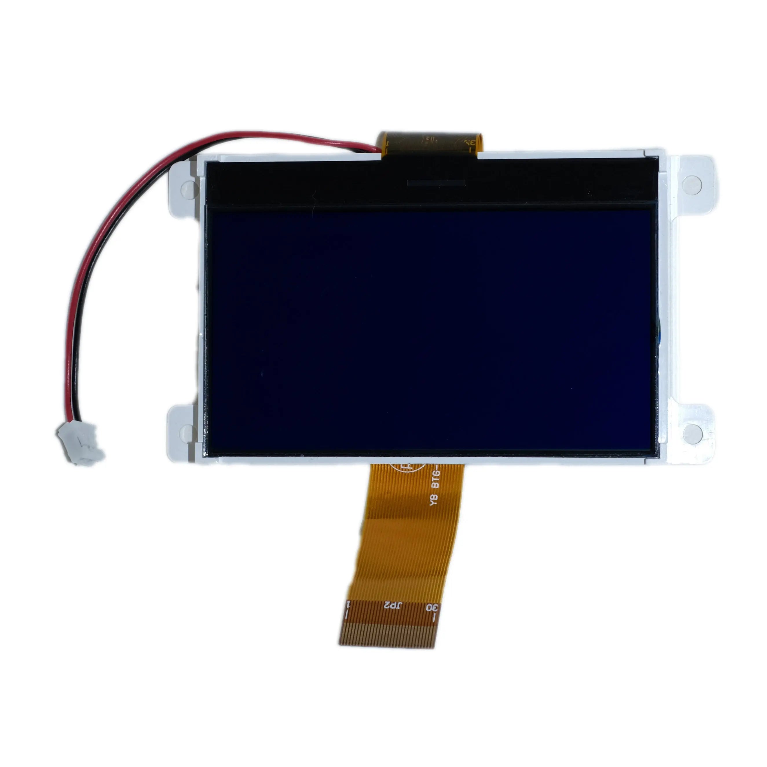
128x64 COG LCD Graphic Display 3.07" - MCU, SPI
- 💹 Enjoy a 20% discount for orders over 500
- 📉 A 15% discount is available for orders ranging from 200 to 499
- 🎁 A 10% discount is available for orders ranging from 50 to 199
- 🎁 A 5% discount is available when ordering 10-49
Interested in customizing this product? Get in touch with us.
Order samples, immediate delivery.
Factory bulk lead time: 3 weeks.
128x64 COG LCD Graphic Display 3.07" - MCU, SPI
- 💹 Enjoy a 20% discount for orders over 500
- 📉 A 15% discount is available for orders ranging from 200 to 499
- 🎁 A 10% discount is available for orders ranging from 50 to 199
- 🎁 A 5% discount is available when ordering 10-49
Resources & Downloads
128×64 COG LCD Graphic Display 3.07" - MCU, SPI
SKU: DM-COG12864-715DM-COG12864-715 is a Chip-on-Glass monochrome graphic LCD with an approximately 3.07-inch viewing-area diagonal, a 128 × 64-dot format, STN negative blue transmissive mode, and white LED backlight. Its integrated ST7565P controller supports an 8-bit 6800-series or 8080-series parallel bus, as well as a serial write interface.
Designed for direct MCU control, the module operates from a 2.7 to 3.3 V logic supply and uses a 1/65-duty, 1/9-bias drive scheme. The specified operating temperature range is -20°C to +70°C, with the display optimized for viewing from the 6:00 direction.

Technical Specifications
Review the display format, controller, interface modes, supply requirements, environmental limits, and key mechanical dimensions used for component selection and initial design planning. Final PCB and enclosure details should follow Figure 1 and the official datasheet.
| Parameter | Verified Specification |
|---|---|
| Product Model | DM-COG12864-715 |
| Display Format | 128 × 64 dots |
| LCD Type | STN negative blue |
| Driver Mode | Transmissive |
| Controller IC | ST7565P |
| Interface | 8-bit parallel MPU interface or serial data input |
| Parallel Interface Selection | 6800-series MPU when C86 is high, or 8080-series MPU when C86 is low, with P/S set high |
| Serial Interface Selection | P/S set low; SI is assigned to D7 and SCL is assigned to D6. Serial operation is write only, and display RAM cannot be read in this mode. |
| Logic Supply | 2.7 V minimum to 3.3 V maximum |
| Digital Operating Current | 0.60 mA typical; 2.0 mA maximum under the datasheet condition |
| Backlight | White LED |
| Preferred View Direction | 6:00 |
| Drive Scheme | 1/65 duty, 1/9 bias |
| Operating Temperature | -20°C to +70°C, absolute maximum range |
| Storage Temperature | -30°C to +80°C, absolute maximum range |
| Module Outline | 89.7 mm wide × 49.8 ± 0.5 mm high. The 89.7 mm dimension uses the drawing's general ±0.2 mm tolerance. |
| LCD Glass Size | 73.0 × 47.5 mm |
| Viewing Area | 69.0 × 36.5 mm |
| Active Area | 63.97 × 31.97 mm |
| FPC Contact Layout | 30 positions with 0.5 mm pitch, as shown in Figure 1 |
| Touch | No touch panel or touch controller is specified in the module datasheet. |
Mechanical Details for Enclosure and PCB Planning
The module measures 89.7 mm wide by 49.8 ± 0.5 mm high. Its 69.0 × 36.5 mm viewing area provides an approximately 3.07-inch diagonal, while the active area is 63.97 × 31.97 mm. Use Figure 1 to confirm mounting-hole locations, FPC orientation, contact side, component clearance, and local tolerances before releasing mechanical tooling.
Drawing-Controlled Features
Review Figure 1 for the mounting-hole positions, FPC bend direction, contact side, component-side clearance, and local dimensions that are not summarized in the table.
Dimensions without an individual tolerance use the drawing note of ±0.2 mm.
Electrical and Optical Characteristics
The LCD logic operates from 2.7 to 3.3 V, while the white LED backlight is specified at 3.4 to 3.6 V forward voltage. The optical data below covers viewing angles, response time, contrast ratio, and the preferred 6:00 viewing direction for display-window and user-interface evaluation.
Viewing and Response Data
Response time at 25°C: The supplied module datasheet lists 300 ms typical and 400 ms maximum for Tr + Tf. Confirm the listed unit with DisplayModule when response time is a critical qualification parameter.
Contrast ratio: 3:1 typical, as listed in the module datasheet.
Preferred viewing direction: 6:00. The 6:00 value describes orientation, not a wide-viewing-angle classification.
Connector, Interface, and Timing Details
The 30-position, 0.5 mm-pitch FPC carries power, control, data, LCD-drive, and interface-selection signals. Configure the module for 6800-series or 8080-series 8-bit parallel operation, or select the serial write interface using SI on D7 and SCL on D6.
30-Pin FPC Interface
The mechanical drawing identifies a 30-position FPC contact with 0.5 mm pitch. Match the contact side and mating-connector geometry to Figure 1 before PCB release.
View ST7565 DocumentationSelect Parallel or Serial
P/S high selects the parallel data bus. P/S low selects serial data input; D7 becomes SI and D6 becomes SCL, while D0 to D5 are fixed high according to the module datasheet.
Select the Parallel MPU Type
With P/S high, C86 high selects the 6800-series interface and C86 low selects the 8080-series interface.
Control Data and Commands
A0 high identifies display data; A0 low identifies command data. Driving /RES low initializes the controller settings.
Plan for Write-Only Serial Operation
Serial data is accepted on the rising edge of SCL, most-significant bit first. Reading display RAM is not possible in serial mode.
The datasheet recommends checking SCL behavior on the actual equipment because line-end reflections and external noise can affect serial operation.
Reliability Test Conditions
The datasheet lists storage, powered operation, humidity, thermal-shock, vibration, and static-electricity test conditions for the LCD module. Use these conditions as a reference during sample qualification, and validate the completed product again in its final enclosure and operating environment.
High and Low Temperature Storage
80°C for 200 hours and -30°C for 200 hours.
High and Low Temperature Operation
70°C for 200 hours and -20°C for 200 hours.
Temperature and Humidity
60°C at 90% RH for 96 hours under the datasheet's no-load condition, excluding the polarizer, followed by drying at normal temperature.
Thermal Shock
-20°C to +70°C for 10 cycles, with the cycle profile shown in the datasheet.
Vibration
The supplied module datasheet lists 10 to 55 Hz, a total fixed amplitude of 15 mm, one 60-second cycle, and 16 minutes in each X, Y, and Z direction. The packing is included in this test. Confirm the listed amplitude when it is part of project qualification.
Static Electricity
VS = 800 V, RS = 1.5 kΩ, CS = 100 pF, applied one time as listed in the datasheet.
The datasheet states that condensation should not be present. For tests marked with Note 2, functional verification is performed after four hours of recovery at normal temperature and humidity.
Engineering Notes Before Design Release
Confirm the host logic levels, backlight drive, FPC mating geometry, reset sequence, and ST7565P initialization settings before PCB and firmware release. These checks address the main electrical, mechanical, and software items required for first-sample bring-up.
Logic-level review: Input thresholds are referenced to VDD. Review level shifting when the host uses 5 V logic or any I/O voltage outside the stated module limits.
Backlight drive: Design the current-control circuit around the datasheet-listed 72 mA typical forward current while observing the listed 100 mA maximum. The forward-voltage specification is 3.4 V minimum, 3.5 V typical, and 3.6 V maximum.
Connector matching: Confirm the 30-position, 0.5 mm-pitch FPC, contact side, exposed contact dimensions, and mating-connector geometry against Figure 1 before ordering production PCBs.
Initialization: Include a controlled /RES pulse and the required ST7565P command sequence in firmware. Confirm display orientation, bias, electronic-volume settings, and address mapping on samples.
System validation: Recheck serial timing, SCL waveform quality, display contrast, view direction, backlight heating, and mechanical clearance in the final assembly.
Confirm Before Ordering When Required
The supplied module datasheet does not state every commercial or optical value. Confirm project-specific requirements with DisplayModule when they are important to your design.
- Brightness or luminance
- Backlight lifetime and module lifetime
- Color gamut
- Exact mating-connector part number
- Module weight
- Touch-panel availability or touch-controller configuration
- Customization, sample availability, MOQ, and lead time
Common Questions
Review the interface mode, logic voltage, touch status, enclosure dimensions, unspecified optical values, and first-sample checks commonly considered before ordering or starting PCB layout.
Is the serial interface standard full-duplex SPI?
The module uses an SPI-like serial data-input arrangement with SI, SCL, A0, and chip-select control. It is write only in serial mode, so display RAM readback is not available.
Can it connect directly to a 5 V microcontroller?
The LCD logic supply is specified from 2.7 to 3.3 V, and its input thresholds are referenced to VDD. Review the host I/O voltage and use level shifting when required.
Does the module include a touch panel?
No touch panel or touch controller is specified in the supplied module datasheet. Confirm any project-specific touch requirement before ordering.
Which dimensions should be used for the enclosure window?
The drawing lists a 69.0 × 36.5 mm viewing area and a 63.97 × 31.97 mm active area. Use Figure 1 to determine the final opening, bezel overlap, tolerances, and assembly clearance.
Are brightness and lifetime values available?
Brightness, backlight lifetime, and overall module lifetime are not specified in the supplied module datasheet. Confirm these values with DisplayModule if they are required for qualification.
What should be checked on the first sample?
Check the FPC and connector fit, reset and initialization sequence, interface selection, addressing direction, contrast setting, serial waveform quality, backlight current, view orientation, and mechanical clearance.
Download Engineering Documents
Use the module datasheet for mechanical dimensions, pin assignments, electrical limits, optical characteristics, timing, and reliability conditions. Use the ST7565 controller document for controller functions, command definitions, addressing, power-control settings, and interface behavior.