








128x64 LCD Graphic Display 3.24" Large - MCU
- 💹 Enjoy a 20% discount for orders over 500
- 📉 A 15% discount is available for orders ranging from 200 to 499
- 🎁 A 10% discount is available for orders ranging from 50 to 199
- 🎁 A 5% discount is available when ordering 10-49
Interested in customizing this product? Get in touch with us.
Order samples, immediate delivery.
Factory bulk lead time: 3 weeks.
128x64 LCD Graphic Display 3.24" Large - MCU
- 💹 Enjoy a 20% discount for orders over 500
- 📉 A 15% discount is available for orders ranging from 200 to 499
- 🎁 A 10% discount is available for orders ranging from 50 to 199
- 🎁 A 5% discount is available when ordering 10-49
Resources & Downloads
128×64 Graphic LCD Module with NT7108 Parallel Interface
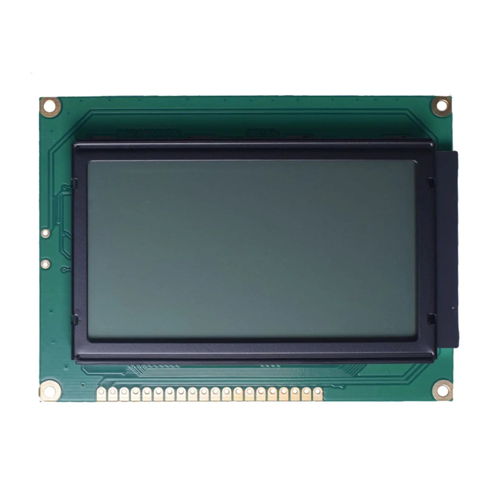
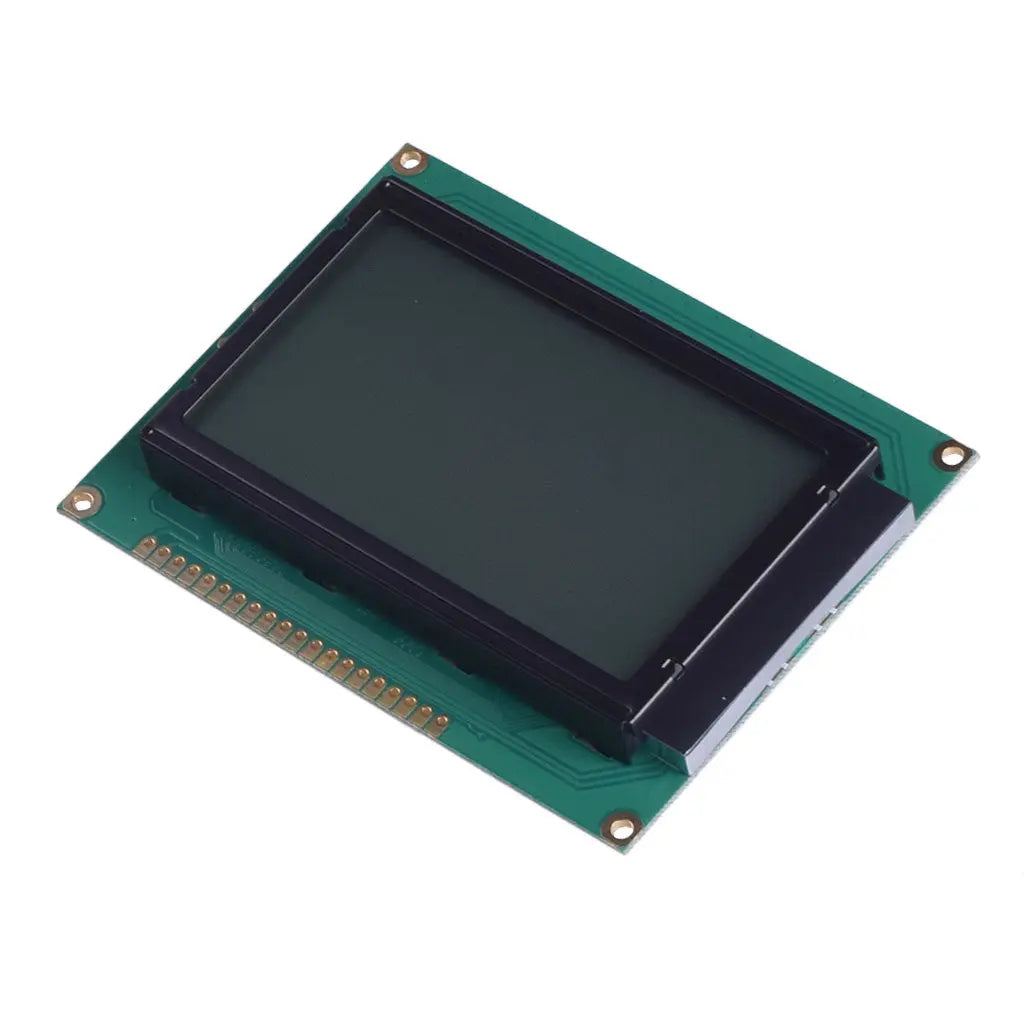
The DM-LCD12864-453 is a monochrome graphic LCD module with a 128×64 dot matrix, FSTN positive transflective display mode, white LED backlight, and 5.0 V parallel MPU interface.
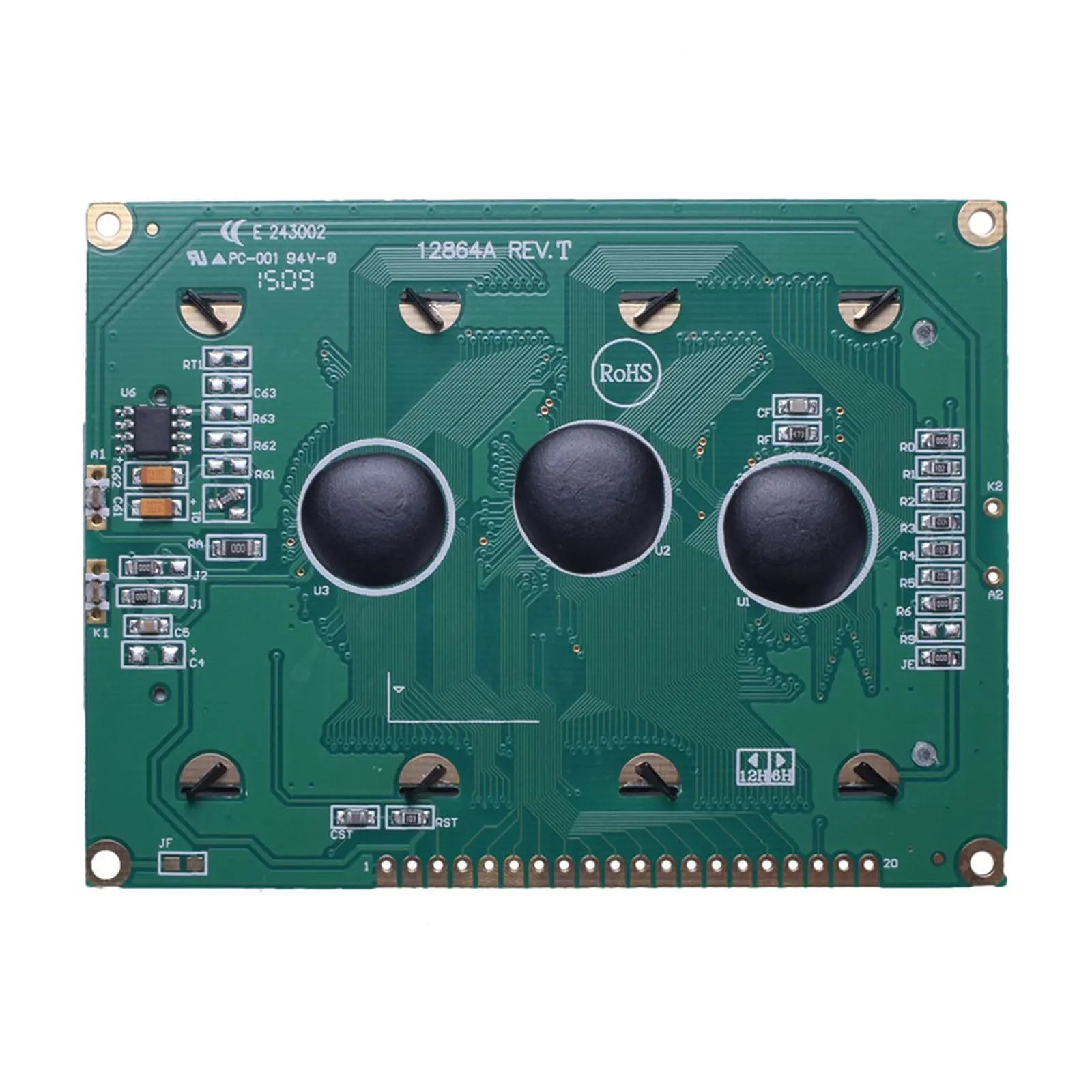
The 20-pin connection provides an 8-bit data bus, read/write control, enable, reset, separate chip-select signals for the two 64-column display areas, LCD contrast control, and backlight power.
Use the datasheet for the exact ordered SKU when confirming optical mode, backlight load, weight, and viewing characteristics. The 453, 454, and 455 versions share the published outline and interface, but their optical and backlight specifications are different.

Available Optical Variants
All three published versions use a 128×64 resolution, NT7108 controller, 5.0 V parallel MPU interface, 6:00 viewing direction, 1/64 duty cycle, and a 93.0×70.0×13.6 mm maximum module outline. Select the model by display mode and backlight requirement.
FSTN Positive, Transflective
FSTN positive transflective display mode with a white LED backlight. This is the primary SKU shown on this product page.
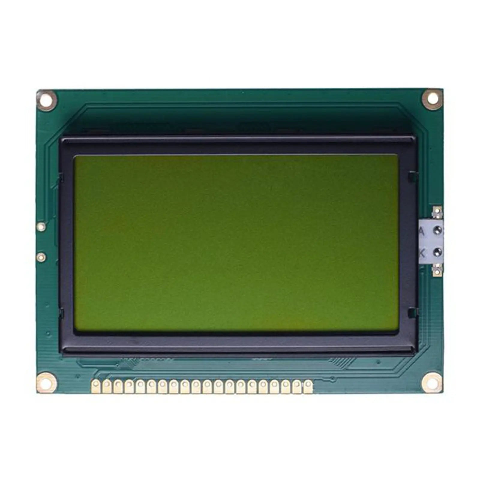
STN Positive, Yellow-Green
Yellow-green transflective display mode with a yellow-green LED backlight.
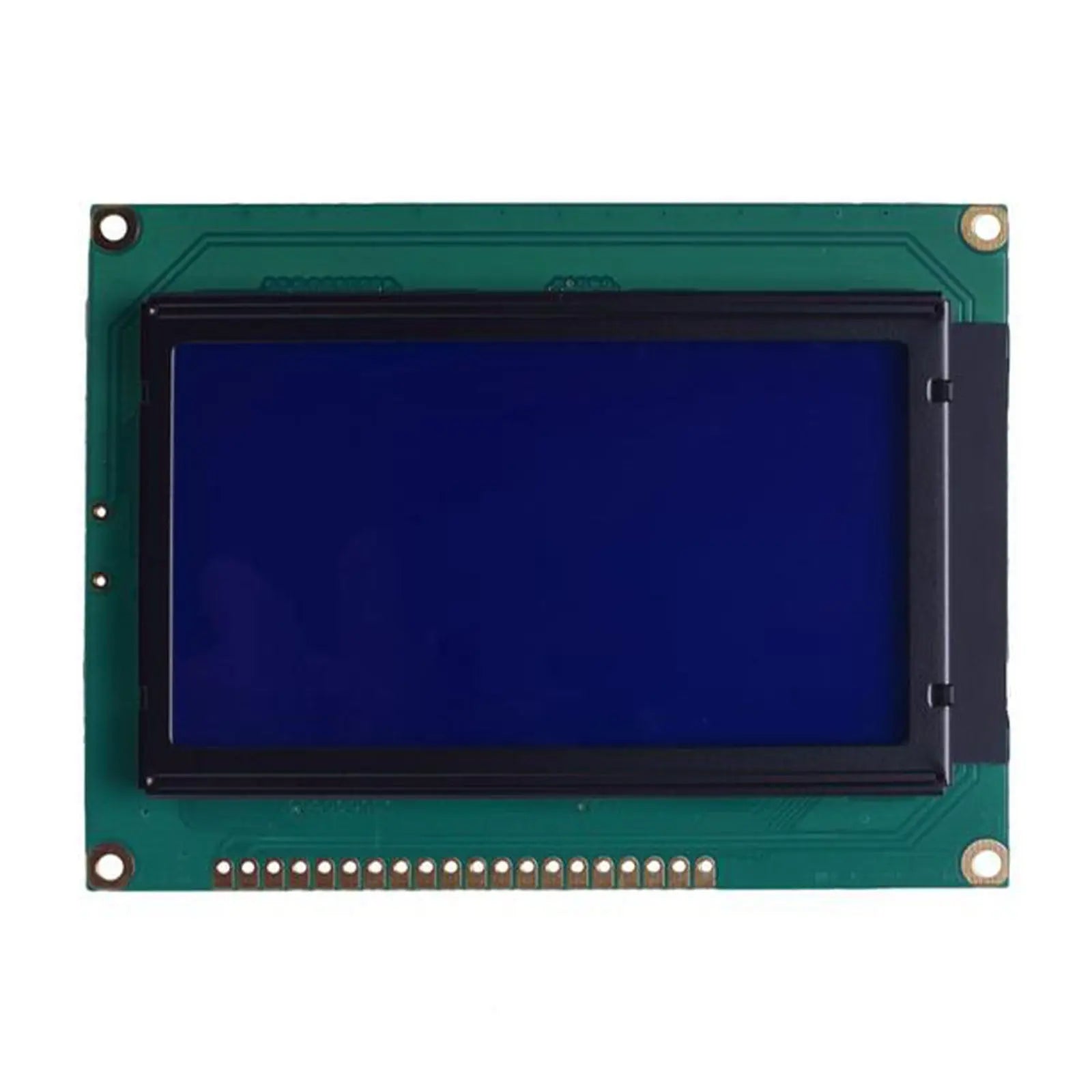
STN Negative, Blue
Blue transmissive display mode with a white LED backlight.
Verified Technical Specifications
The table below applies to the primary SKU, DM-LCD12864-453. Use the model comparison above and the matching datasheet when ordering the yellow-green or blue version.
| Parameter | Specification |
|---|---|
| Resolution | 128×64 dots |
| Display Mode | FSTN positive, transflective |
| View Direction | 6:00 |
| Module Dimension | 93.0×70.0×13.6 mm maximum |
| Power Supply | 5.0 V nominal; 4.5 to 5.5 V specified |
| Backlight | White LED |
| Interface | 8-bit parallel MPU interface |
| Controller IC | NT7108 |
| Operating Temperature | -20°C to +70°C |
| Storage Temperature | -30°C to +80°C |
| Weight | 75.0 g |
Mechanical Details
The published drawing shows the board outline, viewing area, active pixel area, mounting pattern, pin pitch, and maximum assembled thickness. Use the drawing dimensions and tolerances for enclosure and PCB layout.
Parallel Interface and Electrical Integration
The module uses an 8-bit MPU bus. CS1 controls columns 1 to 64 and CS2 controls columns 65 to 128. The Vo input is used for LCD contrast adjustment, while Vout provides the negative voltage used by the display bias circuit.
5 V Logic Requirement
At the specified 5.0 V logic supply, the input-high threshold is at least 0.7×VDD. A 3.3 V host output may not meet this threshold, so verify the MCU logic levels and use level translation when required.
The typical logic supply current is 29.2 mA at VDD = 5.0 V. Backlight power is separate and differs by optical variant.
Timing and Controller Functions
The published MPU timing is based on the module datasheet. Firmware can write display data, read display data, check the busy status, select a page, set a column address, set the display start line, and switch the display on or off.
Enable Cycle
Minimum E cycle: 1000 ns. Minimum E high and low widths: 450 ns each.
Data Setup
Minimum data setup time: 200 ns. Maximum read data delay: 320 ns.
Display RAM Access
Page and column commands select the display RAM location. The column address advances after data access.
Busy Check
DB7 reports the busy status. Send new instructions only when the controller is ready.
Backlight and Optical Data by Model
Backlight voltage, current, viewing angles, contrast, and luminance are model-specific. The luminance values below are measured without the LCD panel and should not be presented as finished-module screen brightness.
| Model | Published Optical and Backlight Data |
|---|---|
| DM-LCD12864-453 | White LED, 3.4 to 3.6 V, 64 mA typical and 80 mA maximum; viewing angles 30° top, 60° bottom, 45° left and right; 5:1 typical contrast; luminance without LCD 440 cd/m² minimum and 550 cd/m² typical. |
| DM-LCD12864-454 | Yellow-green LED, 4.0 to 4.3 V, 297 mA minimum, 330 mA typical, and 396 mA maximum; viewing angles 20° top, 40° bottom, 30° left and right; 3:1 typical contrast; luminance without LCD 220 cd/m² minimum and 280 cd/m² typical. |
| DM-LCD12864-455 | White LED, 3.4 to 3.6 V, 64 mA typical and 80 mA maximum; viewing angles 20° top, 40° bottom, 30° left and right; 3:1 typical contrast; luminance without LCD 440 cd/m² minimum and 550 cd/m² typical. |
Published Environmental Test Conditions
These datasheet test conditions help customers review environmental tolerance before sample evaluation and final product qualification. They do not replace qualification in the finished enclosure.
Check These Points Before Ordering
Choose the exact display mode first, then confirm the electrical, optical, mechanical, and firmware requirements against the matching datasheet.
Model selection: Confirm 453 gray, 454 yellow-green, or 455 blue on the quotation, order, and sample label.
Logic levels: Verify the host output-high level against VIH ≥ 0.7×VDD. Add level translation when the host cannot meet it.
Backlight supply: Size the driver and current limiting for the selected model. The 454 backlight load is substantially higher than the 453 and 455 loads.
Mechanical fit: Check the viewing window, mounting holes, 20-pin header position, maximum depth, and connector clearance.
Contrast circuit: Include the external Vo adjustment shown in the module datasheet and verify the setting in the final enclosure.
Firmware setup: Validate reset, busy checking, page and column addressing, start-line control, and both chip-select regions.
Common Questions
What is the difference between the 453, 454, and 455 models?
They share the published resolution, outline, controller, interface, supply voltage, viewing direction, and duty cycle. Their LCD mode, backlight color, backlight electrical load, optical data, and weight are different.
Can a 3.3 V microcontroller drive the module directly?
Not always. With VDD at 5.0 V, the module requires an input-high level of at least 0.7×VDD. Confirm the MCU output specification and use level translation when necessary.
Does this module include a touch panel?
No touch-panel specification is included in the supplied module datasheets. Treat these models as non-touch displays unless a separate touch configuration is confirmed before ordering.
Is 550 cd/m² the finished display brightness?
No. For the 453 and 455, the 550 cd/m² typical value is identified as luminance measured without the LCD panel. It should not be used as the finished-module brightness value.
How are the 128 columns addressed?
CS1 selects columns 1 to 64 and CS2 selects columns 65 to 128. Firmware must manage both chip-select areas when updating the full screen.
Which document should control the final design?
Use the datasheet and mechanical drawing for the exact ordered module. Use the NT7108 document for controller operation, commands, status, and timing details.
Download Official Technical Documents
Use the model-specific datasheet to confirm dimensions, pin assignment, electrical limits, optical data, timing, reliability conditions, and integration requirements. Use the NT7108 document for controller functions and command details.