








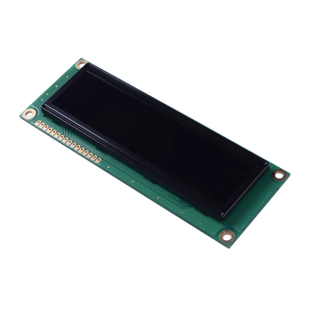
16x2 Character OLED Yellow Large - MCU, SPI, I2C
- 💹 Enjoy a 20% discount for orders over 500
- 📉 A 15% discount is available for orders ranging from 200 to 499
- 🎁 A 10% discount is available for orders ranging from 50 to 199
- 🎁 A 5% discount is available when ordering 10-49
Interested in customizing this product? Get in touch with us.
Order samples, immediate delivery.
Factory bulk lead time: 3 weeks.
16x2 Character OLED Yellow Large - MCU, SPI, I2C
- 💹 Enjoy a 20% discount for orders over 500
- 📉 A 15% discount is available for orders ranging from 200 to 499
- 🎁 A 10% discount is available for orders ranging from 50 to 199
- 🎁 A 5% discount is available when ordering 10-49
Resources & Downloads
16×2 Yellow Character OLED Display with WS0010 and Parallel or Serial MPU Interface
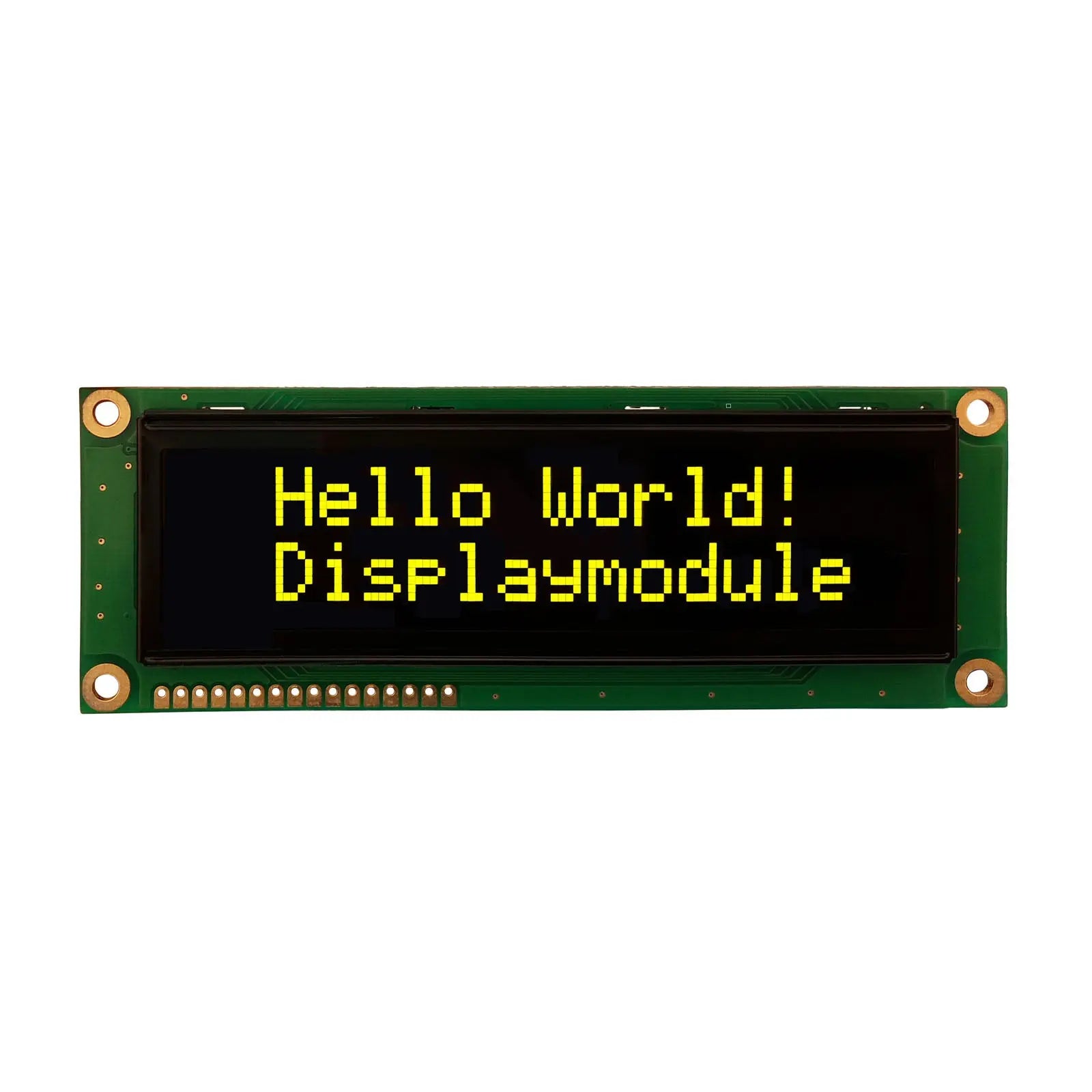
DM-OLED1602-607 is a 16-character by 2-line passive-matrix OLED module with yellow emission and a built-in WS0010 controller. The module datasheet specifies 6800-series parallel as the default interface, with 8080-series parallel and serial interface configurations available through jumper selection.
For engineering review, the module provides a 122.0 ± 0.5 × 44.0 ± 0.5 mm outline with 10.0 mm maximum thickness outline, a 3.0–3.6 V logic supply range with 3.3 V typical operation, and a datasheet absolute-maximum operating and storage temperature limits of -40°C to +80°C.

Mechanical drawing for the DM-OLED1602-607 module, including outline, viewing area, active area, mounting, and 16-pin through-hole dimensions.
Verified Technical Specifications
Key electrical, optical, mechanical, and interface specifications for product selection and hardware integration.
| Parameter | Specification |
|---|---|
| Product Model | DM-OLED1602-607 |
| Display Format | 16 characters × 2 lines |
| Display Mode | Passive Matrix OLED |
| Emitting Color | Yellow |
| Controller IC | WS0010 |
| Interface | Parallel or serial MPU interface; default configuration is 6800-series parallel |
| Available Interface Configurations | 6800-series parallel, 8080-series parallel, and serial |
| Logic Supply Voltage | 3.0 V minimum, 3.3 V typical, 3.6 V maximum |
| 50% Operation Current | 56 mA minimum, 62 mA typical, 65 mA maximum |
| Module Outline | 122.0 ± 0.5 × 44.0 ± 0.5 mm |
| Maximum Module Thickness | 10.0 mm maximum |
| Viewing Area | 99.0 × 24.0 mm |
| Active Area | 91.14 × 18.98 mm |
| Duty | 1/16 duty |
| Weight | 41.8 g |
| Absolute Maximum Operating Temperature | -40°C to +80°C |
| Absolute Maximum Storage Temperature | -40°C to +80°C |
| Horizontal Viewing Angle | 160° minimum |
| Vertical Viewing Angle | 160° minimum |
| Response Time at 25°C | 20 µs typical |
| Contrast Ratio | 2000:1 minimum |
| Brightness at 50% Check Board | 70 cd/m² minimum, 90 cd/m² typical |
| Operating Lifetime | 80,000 hours minimum, 100,000 hours typical, using the lifetime definition stated in the module datasheet |
Optical and Electrical Performance
The specified contrast, viewing angle, response time, brightness, supply voltage, and operating current support display selection, power planning, and system integration.
Specified Minimum Contrast Ratio
2000:1The display provides a minimum contrast ratio of 2000:1 and minimum viewing angles of 160° horizontally and vertically.
Mechanical Dimensions for Integration
The 122.0 × 44.0 mm module format, defined viewing and active areas, mounting geometry, and 16-position 2.54 mm-pitch through-hole pin row support PCB and enclosure integration.
Mounting and Clearance
The module has a 10.0 mm maximum thickness and a 37.0 mm mounting-hole center spacing across the short axis. The dimensional drawing provides the required reference for mounting-hole, pad, bezel, and connector clearance.
Interface Configuration and Pin-Level Signals
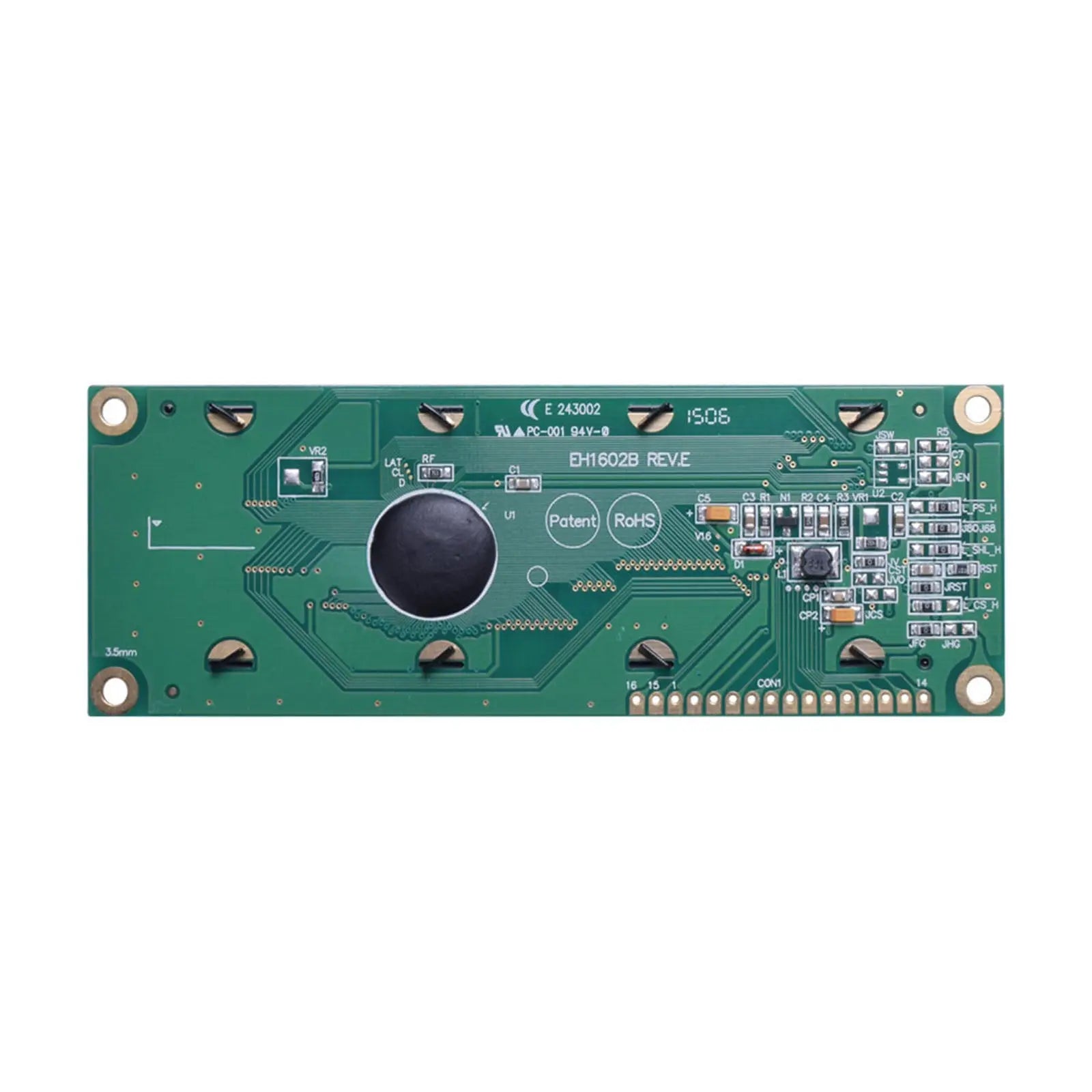
The module supports 6800-series parallel, 8080-series parallel, and serial interface configurations. The default configuration is 6800-series parallel, with interface mode selected by jumper settings.
6800-Series Parallel
This is the default module interface configuration. The parallel pin table uses RS, R/W, E, and DB0–DB7 signals in addition to VSS and VDD.
8080-Series Parallel
The datasheet lists 8080-series parallel as an alternate jumper-selectable mode. Review the WS0010 controller timing and module jumper table before changing the default configuration.
Serial Interface
In serial mode, the module pin table identifies SCL for serial clock, SDO for serial data output, SDI for serial data input, and active-low /CS for chip select.
Serial clock
Serial data output
Serial data input
Active-low chip select
WS0010 Controller Functions Relevant to Integration
The built-in WS0010 controller provides character generation, display control, cursor functions, memory resources, and parallel or serial data-transfer modes for the module.
Built-In WS0010 OLED Driver / Controller
The controller specification documents 4-bit and 8-bit MPU operation, 6800-series and 8080-series parallel interfaces, serial interface support, display RAM, character generation, and display-control instructions.
Display and Cursor Instructions
The WS0010 specification includes commands for display clear, cursor home, display on/off, cursor on/off, character blink, cursor shift, and display shift.
Selectable Character ROM Sets
The module datasheet includes English/Japanese, Western European I, English/Russian, and Western European II character font tables.
Custom Character Memory
The controller specification lists 64 × 8-bit CGRAM, supporting up to eight 5 × 8 custom character fonts or four 5 × 10 custom character fonts.
4-Bit, 8-Bit, and Serial Data Transfer
The WS0010 documentation covers 4-bit and 8-bit MPU data transfer for the parallel interfaces and a separate serial interface mode.
Reliability and Environmental Test Conditions
The module is documented with temperature, humidity, thermal shock, vibration, mechanical shock, atmospheric-pressure, and static-electricity test conditions for environmental and transport evaluation.
The datasheet also lists an atmospheric-pressure test at 115 mbar for 40 hours and a static-electricity test condition of VS = 800 V, RS = 1.5 kΩ, and CS = 100 pF, applied one time.
Engineering Notes Before Design Release
Design Integration Checklist
Review electrical limits, jumper settings, pin assignments, mechanical dimensions, and environmental requirements before finalizing the PCB and enclosure.
Confirm the Interface Configuration
The default configuration is 6800-series parallel. Review the jumper-selection table before specifying 8080-series parallel or serial operation.
Design Around 3.3 V Typical Logic Supply
The module electrical table specifies VDD from 3.0 V to 3.6 V, with 3.3 V typical. Check host logic levels and power stability against the module limits.
Use the Mechanical Drawing for PCB and Enclosure Release
Verify the 16-pin 2.54 mm pitch row, module outline, active area, viewing area, mounting-hole geometry, and maximum thickness before finalizing hardware.
Interpret Lifetime Using the Datasheet Definition
The stated lifetime is defined by luminance decaying to below 50% of the initial value. The datasheet notes that the lifetime estimate is extrapolated from accelerated-condition data and that screen-saving mode can extend OLED lifetime.
Confirm Any Requirement Not Listed in the Module Datasheet
The supplied module datasheet does not specify a touch panel, touch controller, or I2C interface. Confirm any alternate interface, touch, connector, customization, or lifecycle requirement with DisplayModule before ordering.
Common Questions Before Sample Evaluation
Answers to common questions about interface selection, power supply, lifetime definition, and project-specific configuration.
What interface is the module configured for by default?
The DM-OLED1602-607 module datasheet identifies 6800-series parallel as the default configuration. The jumper table also lists 8080-series parallel and serial configurations.
Does the supplied documentation specify an I2C interface?
The supplied module datasheet specifies 6800-series parallel, 8080-series parallel, and serial interface modes. It does not document an I2C interface. Confirm any alternate interface requirement with DisplayModule before ordering.
What serial signals are defined by the module datasheet?
The serial pin table identifies SCL, SDO, SDI, and active-low /CS. Use the module pin description and the WS0010 timing information when planning host-controller integration.
What supply voltage should be planned for?
The module electrical table specifies a 3.0 V minimum, 3.3 V typical, and 3.6 V maximum logic supply voltage.
How is the 80,000 to 100,000 hour lifetime figure defined?
The module datasheet defines lifetime as the time until luminance has decayed to below 50% of its initial value. It also states that the estimate is extrapolated from accelerated-condition life data.
Is a touch panel or touch controller specified?
The supplied DM-OLED1602-607 module datasheet does not specify a touch panel or touch controller. Confirm any project-specific touch requirement before ordering.
Technical Resources and Downloads
Use the module datasheet for mechanical, electrical, optical, pin-assignment, interface-selection, and reliability information. The WS0010 controller documentation provides controller-level command, timing, memory, and interface details. The Arduino library and examples provide an additional implementation resource for development review.