8-bit / 16-bit
With IM1 = 0, IM0 = 0 selects 8-bit operation and IM0 = 1 selects 16-bit operation.


Popular Products


Interested in customizing this product? Get in touch with us.
Order samples, immediate delivery.
Factory bulk lead time: 3 weeks.
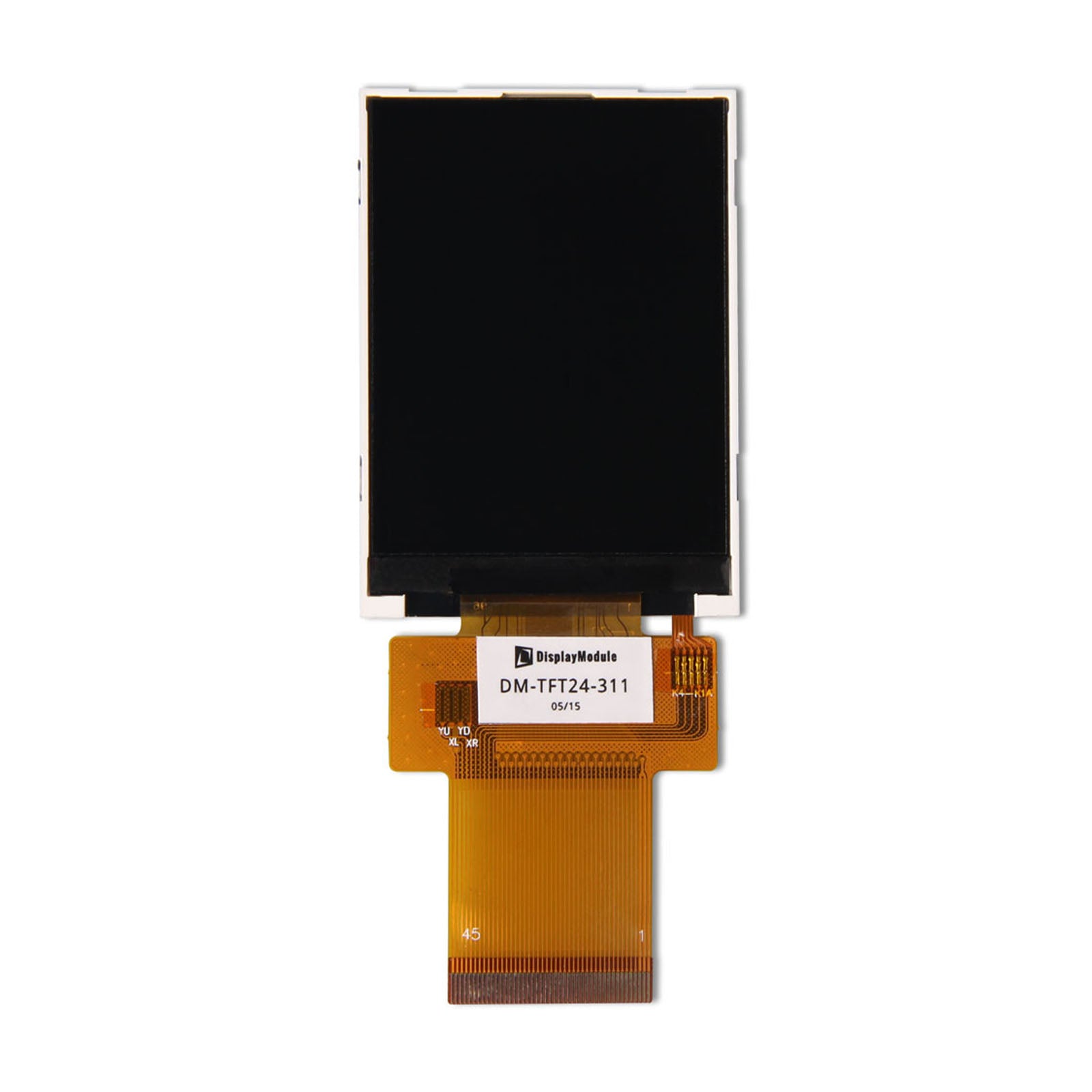
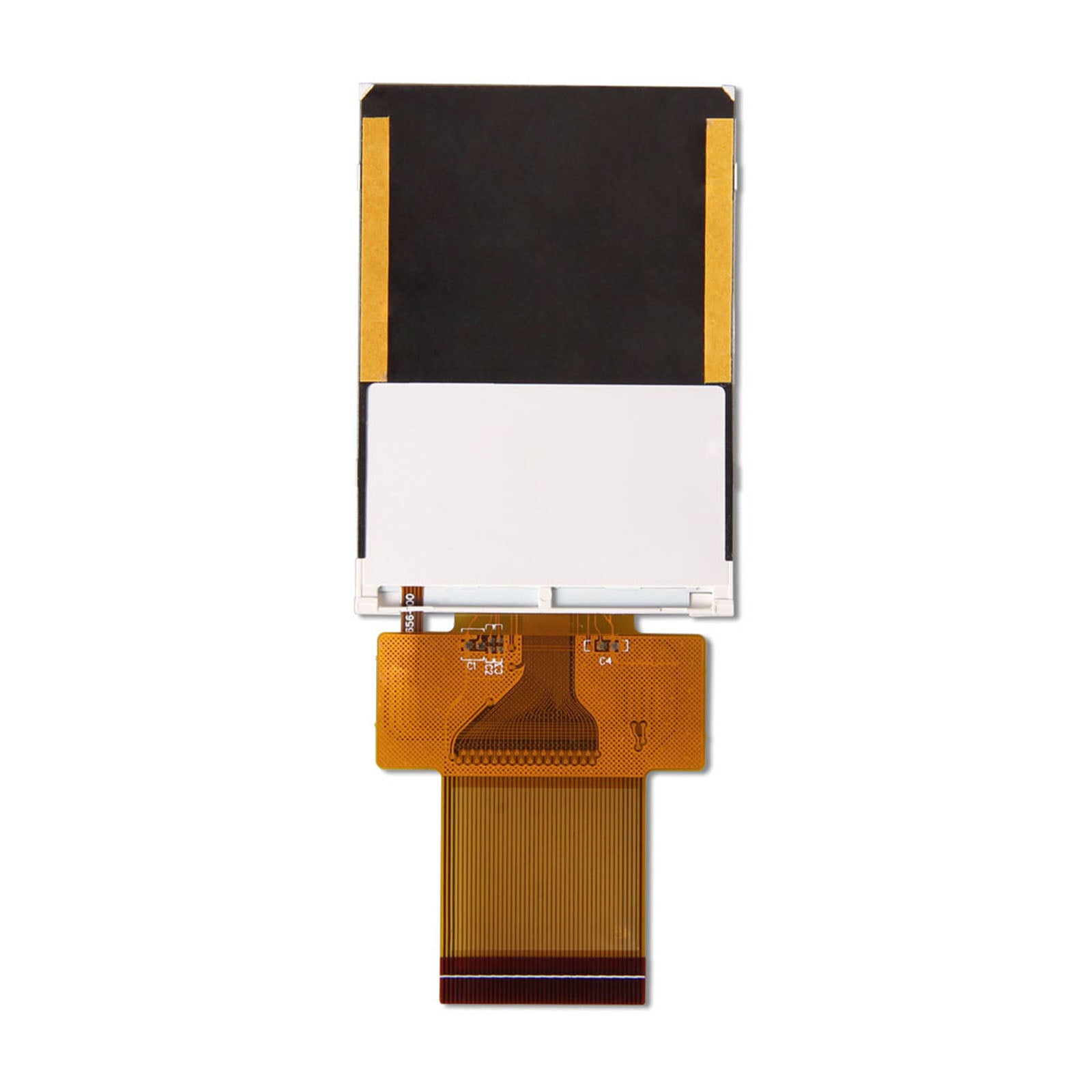
2.4" TFT Display 240x320 - SPI, MCU, RGB
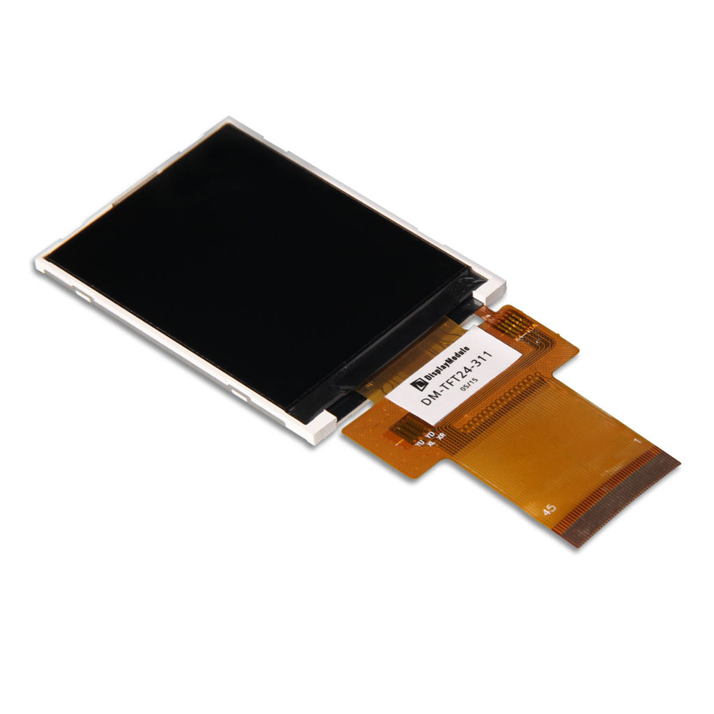
DM-TFT24-311
A 2.4-inch non-touch display with a choice of host interfaces. DM-TFT24-311 combines a 240 × 320 portrait image, ST7789V controller and MCU, serial or RGB connections in a 10.7 g assembly.
Select the interface to match your host and use the module-specific 45-pin assignment. The four-LED backlight is specified at 250 cd/m² minimum with IF = 80 mA.
 + Click to enlarge
DM-TFT24-311 uses an ST7789V controller with a 240 × 320 colour matrix. Interface choices include parallel MCU, 3-wire or 4-wire serial, and 16-bit or 18-bit RGB.
The IM pins select the operating mode. Parallel and serial interfaces use command/data transfers, while RGB mode adds a pixel bus with synchronization, data-enable and pixel-clock signals. The controller datasheet provides the command reference for these modes.
The ST7789V module exposes hardware selectors for parallel and serial operation. In parallel mode, IM1 and IM0 define the number of data lines used by the host.
With IM1 = 0, IM0 = 0 selects 8-bit operation and IM0 = 1 selects 16-bit operation.
With IM1 = 1, IM0 = 0 selects 9-bit operation and IM0 = 1 selects 18-bit operation.
IM2 = 0 selects parallel operation; IM2 = 1 selects serial operation. RESET on pin 7 is active low, and CS on pin 8 is low-enable.
A matching mode-pin setting, data-bus connection and controller initialization form the host interface. The controller datasheet supplies the detailed transfer and command definitions.
Hardware-interface reference →| Parameter | Specification |
|---|---|
| Product model | DM-TFT24-311 |
| Display size | 2.4 inch |
| Resolution | 240 × 320 pixels |
| Display connection | MCU / 3- or 4-wire SPI / 16- or 18-bit RGB |
| Controller / panel | ST7789V |
| Display colours | 65K / 262K |
| Touch configuration | No touch |
| Supply | VDD: 2.4–4.2 V; 3.3 V typical |
| Luminance | 250 cd/m² minimum at IF = 80 mA |
| Operating / storage temperature | −20 to +70 °C / −30 to +80 °C (absolute maximum ratings) |
VDD is 2.4–4.2 V and VDDIO is 1.65–4.2 V, both 3.3 V typical. Typical digital operating current is 4 mA.
Input thresholds are referenced to VDDIO: low-level input is at most 0.3 × VDDIO and high-level input is at least 0.7 × VDDIO. These logic levels form part of the electrical connection between the host and display.
The flexible connection exposes the timing and LED signals as distinct groups. This is useful when arranging the host PCB around the display connection.
VSYNC, HSYNC, ENABLE and DOTCLK provide frame synchronization, line synchronization, active-data enable and pixel clock respectively.
SDO is the SPI output pin. Its output changes on the falling edge of SCL; the module pin description permits it to remain open when unused.
LEDA is the backlight anode on pin 36. LEDK1–LEDK4 occupy pins 37–40 for the four-LED assembly.
The same module supports several display modes, so timing-pin usage depends on the chosen interface. The backlight remains a separate electrical load from the image-data connection.
Connector signal reference →Choose the module around its host interface, viewing position and flexible connection.
The ST7789V panel provides 65K or 262K colours. Use the selected MCU, serial or RGB connection for the host’s graphics output.
The mechanical drawing shows the FPC bend route and cover-window reference. Allow the specified clearances around the 10.7 g assembly.
Pins 41–44 are NC on this model. Plan any external controls as part of the host product rather than connecting them to those unused positions.
The backlight provides 250 cd/m² minimum luminance at IF = 80 mA. Its typical forward voltage is 3.2 V, and forward current is 60 mA minimum and 80 mA typical.
The optical specification includes 500:1 typical contrast and 30 ms typical response time at 25 °C. The preferred viewing direction is 12 o’clock; typical angles are 45° top/left/right and 20° bottom.
The optical specification describes more than the 250 cd/m² minimum luminance. Response time, contrast and uniformity characterize different aspects of the displayed image.
The optical response time is specified at 25 °C. It measures the panel transition rather than the host bus-transfer or application-rendering time.
Contrast is the optical ratio between light and dark states under the specified conditions. It is separate from the 65K / 262K colour modes.
The illumination-uniformity entry is a minimum. It describes light distribution across the panel, rather than centre luminance.
These values can be considered together with the 12 o’clock viewing direction and the installed screen angle. The finished enclosure window contributes its own reflections and transmission.
Optical-performance reference →VDDIO is the interface reference: input low is at most 0.3 × VDDIO, and input high is at least 0.7 × VDDIO up to VDDIO. The digital interface supply is specified at 1.65–4.2 V; the logic supply VDD is 2.4–4.2 V.
Set IM2 = 0 for parallel operation. IM1/IM0 = 00 selects 8-bit, while 01 selects 16-bit. Use the corresponding data wiring and ST7789V command sequence; this SKU is not an ILI9341V module.
No. Pins 41–44 are NC on DM-TFT24-311. The display and four-LED backlight use the other assigned pins; pin 35 SDO may be left open when serial output is unused, as stated in the pin description.
For DM-TFT24-311 support, identify the selected MCU, serial or RGB mode and include the IM pin states. Supply the actual VDDIO level and host pin map when discussing digital-interface connections.
Request this SKU for a 10.7 g non-touch assembly. Include the FPC route and viewing-window requirements from your enclosure design when arranging samples or a volume quote.
The DM-TFT24-311 PDF covers the non-touch module pinout, interface supplies and backlight. The ST7789V datasheet supplies the controller command reference.